System manual
2SM0974070 A 01
Safety
In order to guarantee safe operation, these safety
instructions must be read before you start using this
equipment.
• Do not open the enclosure. This can cause damage,
shortcircuiting or electrical shocks.
• Do not expose the equipment to extreme temperatures.
This can cause deformation of the enclosure or
damage to internal components.
• Repairs may only be made by the manufacturer.
• The equipment must be installed as shown in this
manual.
Before you start using this equipment, please read this manual
carefully and follow all instructions. This installation manual
describes the functions of the equipment, outlines the
connection options and explains how to put the equipment into
operation. We recommend that you keep this manual in a safe
place for reference purposes.
If you have any questions or issues concerning the operation
of this equipment, consult the relevant section in the manual or
contact the Orlaco Products BV Service department.
The camera/display systems from Orlaco comply with the latest CE,
ADR, EMC and mirror-directive regulations, where applicable. All
products are manufactured in accordance with the ISO 9001 quality
management system, IATF 16949 quality automotive, ISO 14001
environmental management systems and all Ex products with the
IECEx scheme and ATEX directives, where applicable.
Contents page
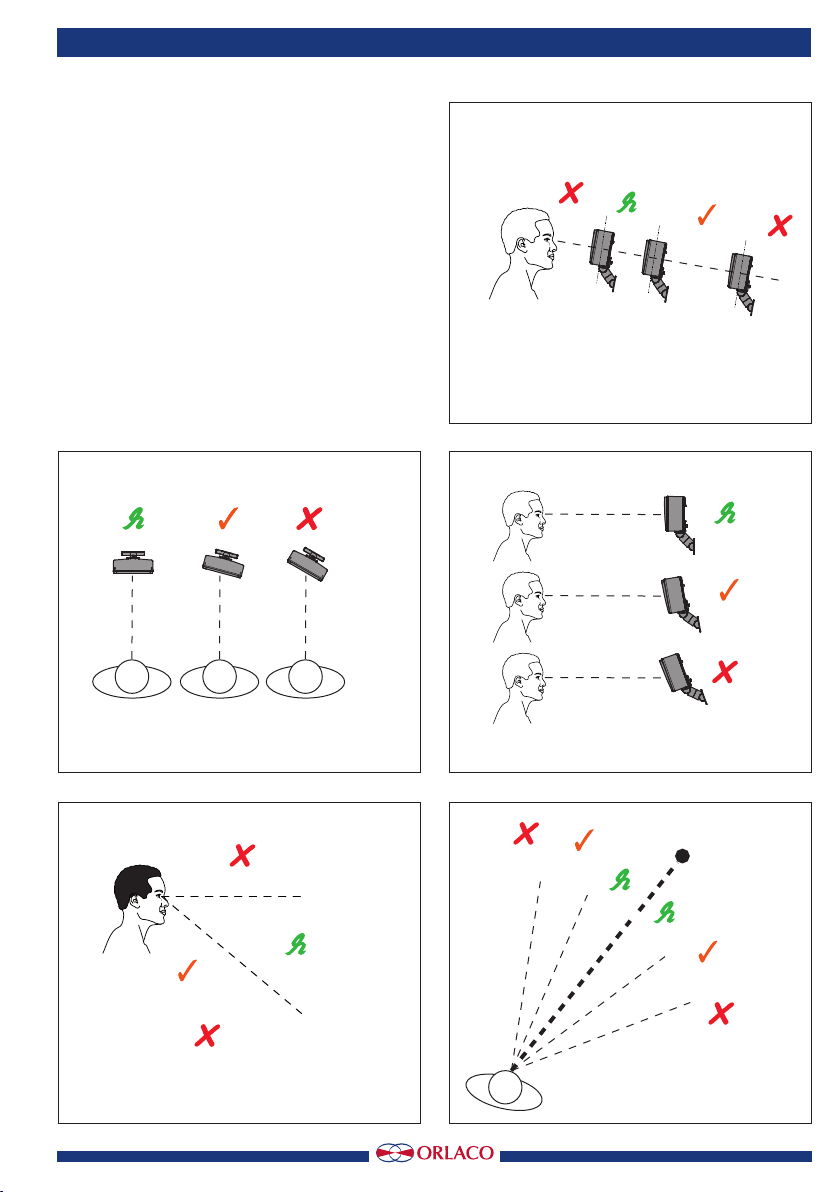
1. Monitor placement 3
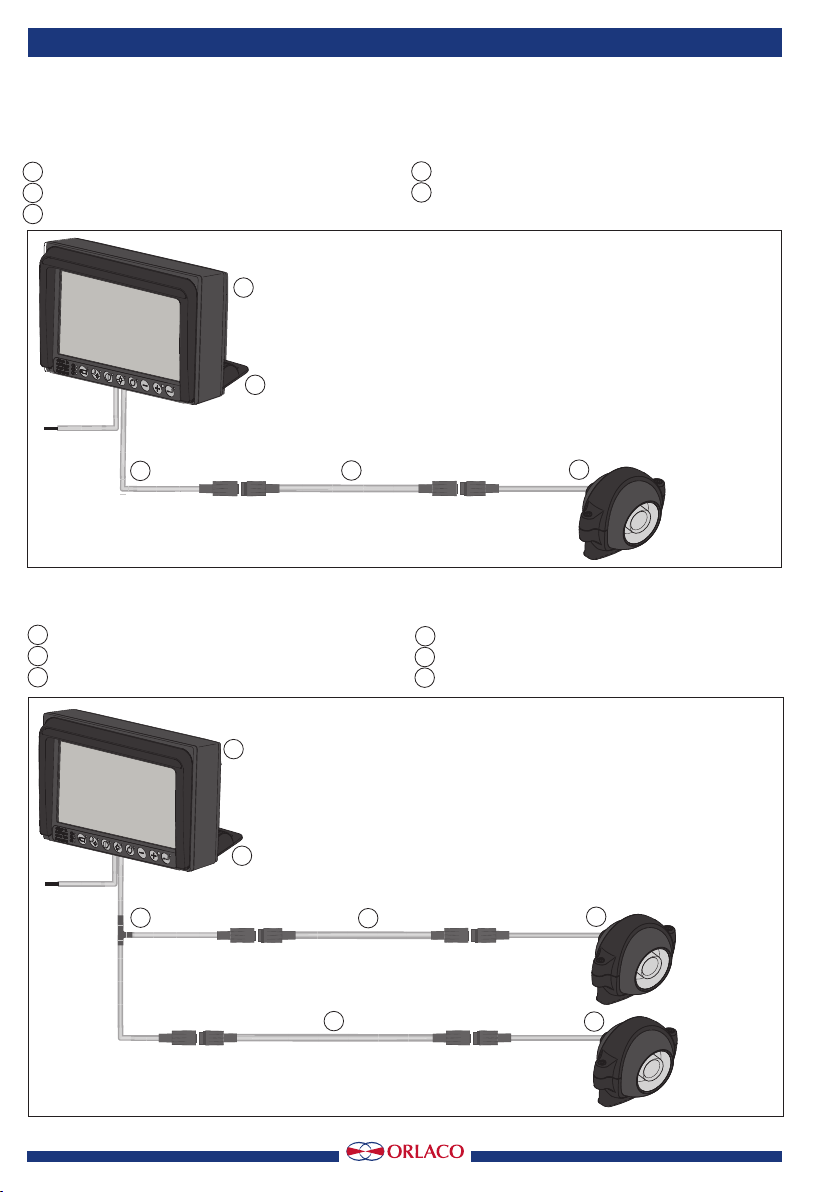
2. System overview kits 4
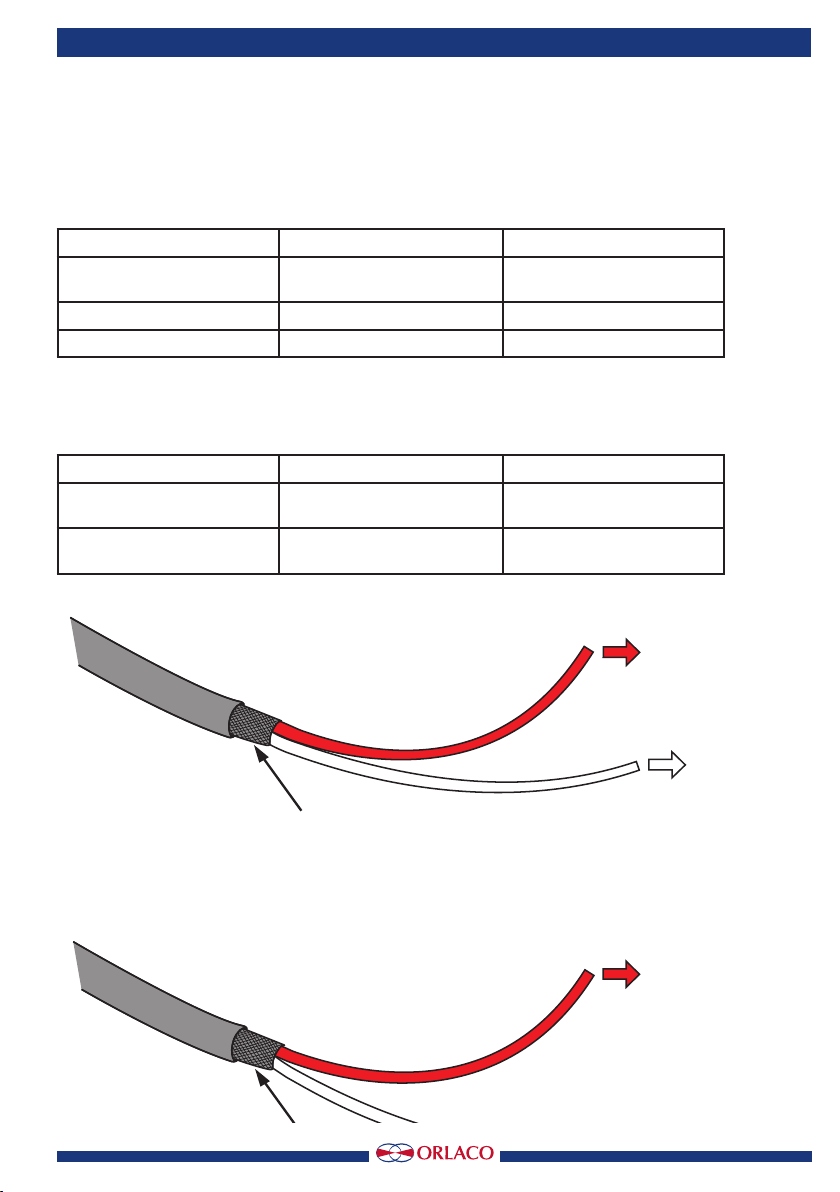
3. EMC 5
4. Technical specifications 6
5. Mounting and demounting Display 7
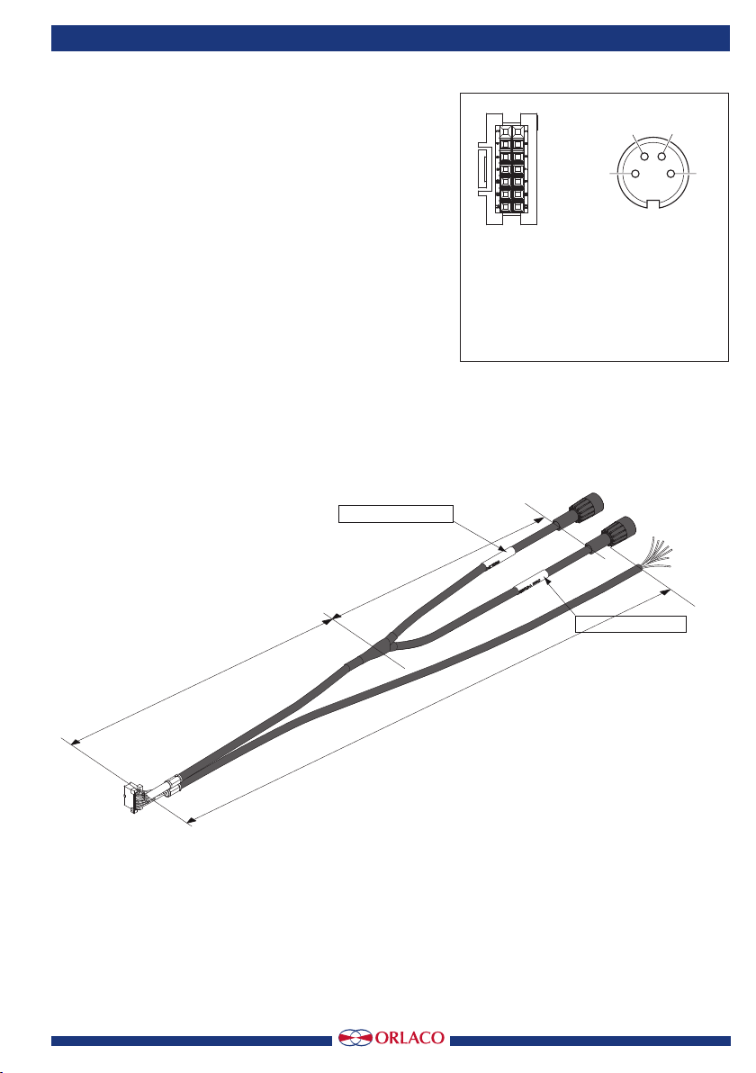
6. Electrical connections 8
7. Electrical connections 9
8. Mounting the cable clamp 10
9. Disposal 11
10. Genaral terms and conditions 11
11. Release notes 11
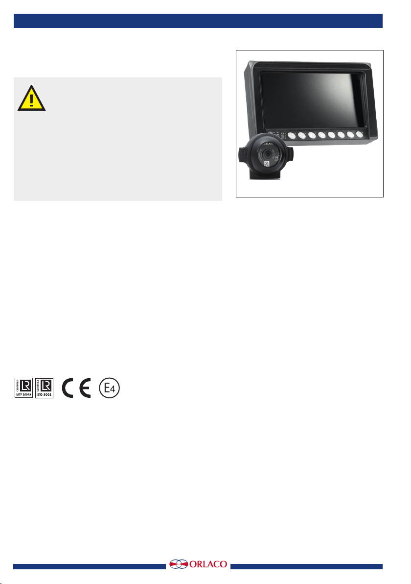
Economy line single camera kit
Economy line dual camera kit
Available documentation:
Data sheet:
DS0207700 Display 7” Economy
DS0146010 Camera CMOS 115° PAL 24V
User Manual:
UM0972040 Display 7” Economy Line