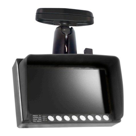
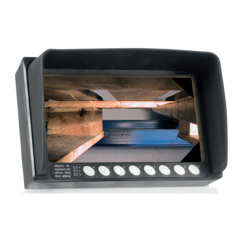
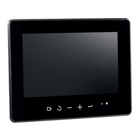
Orlaco Loadview LV7080 User guide

ENGLISH
ORLACO PRODUCTS BV
Albert Plesmanstraat 42, 3772 MN Barneveld
PO Box 193, 3770 AD Barneveld
The Netherlands
Phone: +31 (0) 342 404555
Fax: +31 (0) 342 404556
E-mail: [email protected]
Internet: http://www.orlaco.com
Lufng jib crane
Loadview
System manual
Manual No. SM0974050 R1-2
11/2013
Set LV7080 (Art. No. 0402980)
Set LV7085 (Art. No. 0406720)
Set LV7085 (Art. No. 0406720) Set LV7080 (Art. No. 0402980)

2
ENGLISH
SM0974050 R1-2
System manual
Lufng jib crane Loadview
Set LV7080 and Set LV7085
Safety
In order to guarantee safe operation, these safety
instructions must be read before you start using this
equipment.
• Do not open the enclosure. This can cause damage,
short-circuiting or electrical shocks.
• Do not expose the equipment to extreme
temperatures. This can cause deformation of the
enclosure or damage to internal components.
• Repairs may only be undertaken by the
manufacturer.
• The equipment must be assembled as shown in this
manual.
Contents Page
1. Introduction 3
2. System overview 3
3. Mounting AF-Zoom Camera bracket 4
3.1. Oil Damped Camerabracket (0701200) 4
3.2. Adjustment damping 4
3.3. Setting camera angle 4
4. Mounting AFI Camera 5
4.1. Mounting OGB Adapter quick release to the crane 5
4.2. Adjusting damping 5
4.3. Operation AFI camera 6
4.4. Electrical installation 6
5. Power supply 7
5.1. Electrical connections 7
5.2. System overview 7
5.3. Dimensions 7
6. Mounting monitor 7” 8
7. Mounting monitor 12” 9
8. Release notes 10
Before you start using this equipment, please read this manual
carefully and follow all instructions. This system manual de-
scribes the connection and explains how to put the equipment
into operation. We recommend that you keep this manual in a
safe place for reference purposes.
If you have any questions or issues concerning the operation
of this equipment, consult the relevant section in the manual or
contact the Orlaco Products BV Service department.
The camera/display systems from Orlaco comply with the latest
CE, ADR and EMC regulations. All products are manufactured in
accordance with the ISO 9001 quality management system, ISO
14001 environmental management systems and all Ex products
with the IECEx scheme and ATEX directives.
Available documentation
Data sheets:
DS0103530 AF-Zoom Camera Pal Serial
DS0701200 Compact Oil Damped Bracket
DS0208622 Monitor 7” RLED Serial R6B
DS0411160 Monitor 12” RLED Serial
DS0910250 Quick release Set Bolt version
DS0503810 Power supply 115-230V/24V external devices
DS0502630 Foot switch Zoom Crane
DS0304400 Cable 7pM-7pF 85m
User manuals:
UM0972080 Monitor 7” LEDD/RLED
UM0972050 Monitor 12”
Set contains:
0103530 AF-Zoom camera
0208622 Monitor 7” RLED Serial R6 B
0304400 Cable 7pM-7pF 85m
0502630 Foot switch Zoom Crane
0503810 Power supply 115-230V/24V external devices
0701200 Oil damped camera bracket
0910250 Quick release set bolt version
Set contains:
0103530 AF-Zoom camera
0411160 Set Monitor 12” RLED Serial R6
0304400 Cable 7pM-7pF 85m
0502630 Foot switch Zoom Crane
0503810 Power supply 115-230V/24V external devices
0701200 Oil damped camera bracket
0910250 Quick release set bolt version
Set LV7085 (Art. No. 0406720)
Set LV7080 (Art. No. 0402980)
Installation manuals:
IM0973270 Monitor 7” RLED
IM0701200 Compact Oil Damped Bracket
IM0973360 Camera AFI
System manual
SM0973230 Monitor 12” RLED

ENGLISH
3
SM0974050 R1-2
System manual
1. Introduction
The crane operator can see immediately on his monitor when a
lifting operation could possibly become dangerous. The operator
is no longer dependent on information from other persons by
means of a portable radios. He can make the right decisions
without delay and thus prevent accidents on site. There is also
a far lesser chance of any misunderstandings occurring as the
Loadcam system makes it possible for the operator to verify
the instructions from the signalman. This manual describes the
installation of the AF-Zoom Camera and the AFI Camera with a 7”
monitor or a 12” monitor.
2. System overview
0701200
0103530
0304400
0304400
0502630
0910250
0502630
Power
115-230V
0503810
Monitor 7”
0208622
Fitted to the tip
of the jib
Power
115-230V
Monitor 7”
0208622
In the cabin
Fitted to the tip
of the jib
0103610 / 0103620
0910250
AF-Zoom camera
Set LV7080 with Monitor 7”
Set LV7085 with Monitor 12”
Optional: AFI camera
Monitor 12” RLED
0411160
Monitor 12” RLED
0411160
In the cabin
0503810

4
ENGLISH
SM0974050 R1-2
System manual
3.2. Adjustment damping
See figure 2.
It is possible to adjust the pressure using the socket head
wrench provided. On the cover is an M6 socket head screw (A)
which can be turned in and out. Fully turned in; provides
maximum damping; use this position in the summer. Fully
turned in, than one turn back; provides minimum damping; use
this position in the winter. The damping can be felt by turning
the shaft and simultaneously turning the screw.
Mounting bracket set additional
A
Fitted to the tip of
the telescopic boom
3.3. Setting camera angle
See figure 3.
1. Set the crane in the highest working position.
2. Turn the bolt (1) up until the hoisting hook is shown in the
centre of the monitor.
3. Lock the bolt with nut (2),
Safety remark: x this nut (2) extra well!
Max.
1
2
Figure 1B
Figure 2
Figure 3
3. Mounting camera bracket
3.1. Oil Damped Camerabracket (0701200)
See figure 1A. Art. No. 0910250 Quick release set bolt version.
Mount at first the mounting bracket to the AF-Zoom Camera with
the included mounting bracket, according figure 1A. Use for this
the following bolts nuts and washers.
4x Nut, stainless steel, A2 M6
4x Washer, stainless steel, A2 M6
4x Washer, ST6, 100 HV
4x Button head screw, stainless steel, M6 x 16
Provided safety chain is fixed at the same time with this assem-
bly on the AF-Zoom, see figure 1B.
Mounting the bracket plate on the crane with the 2 M8 bolts and
2 M8 washers (included), see figure 1B
• Or use the Mounting Bracket Set Additional, Art. No. 0910260,
the Compact Oil Damped Bracked can be mounted in different
ways to the crane. See figure 2
Important:
Check that the unit/ camera is hanging straight above the load,
or in between main and aux, hoist, and that it can move freely.
The camera can be fitted to the side or the bottom of the boom-
tip.
“ Make sure that every possible dropped object is being
secured with the safety chain!! “
45°
The Safety chain
should be fitted
to the mast,
not to the
Suspension tube.
74,0°
74,0°
45,0°
74,0°
74,0°
45,0°
74,0°
74,0°
45,0°
45°
45°
45°
74,0°
74,0°
45,0°
74,0°
74,0°
45,0°
74,0°
74,0°
45,0°
45°
45°
45°
Figure 1A

ENGLISH
5
SM0974050 R1-2
System manual
ENGLISH
4. Mounting AFI Camera
4.1. Mounting OGB Adapter quick release to the crane
See figure 4. Art. No. 0910250 Quick release set bolt version.
Mount at first the mounting bracket to the AF-Zoom Camera with
the included mounting bracket, according figure 4. Use for this
the following bolts nuts and washers.
4x Nut, stainless steel, A2 M6
4x Washer, stainless steel, A2 M6
4x Washer, ST6, 100 HV
4x Button head screw, stainless steel, M6 x 16
Provided safety chain is fixed at the same time with this assem-
bly on the AF-Zoom, see figure 5.
Mounting the bracket plate on the crane with the 2 M8 bolts and
2 M8 washers (included), see figure 4
The safety chain should be fitted to the mast, not to
the Suspension tube.
Note that the holes in the Suspension tube for the
Lock pin in the right way at an angle of 45° to the
mast is mounted, see overview mast positions in
figure 6.
4.2. Adjusting damping
The maximum damped deflection of the AFI is 74° to the left and
74° to the right, see figure 7. It is possible to adjust the pressure
of the damper with a Allen key, 3mm. On the cover there is a
screw M6 (A), see figure 7, which can be turned to the plus and
minus position.
Plus provides maximum damping; use this position in the sum-
mer. Turn the adjusting screw entirely to plus side.
Minus provides minimum damping; use this position in the win-
ter. Turn the adjusting screw entirely to plus side; then one twist
to the Minus side. The damping can be felt by turning the shaft
and simultaneously twisting the screw. See figure 7.
Figure 4
Figure 6
74,0°
74,0°
45,0°
74,0°
74,0°
45,0°
74,0°
74,0°
45,0°
45°
45°
45°
Figure 7
Rotation angle:
74° to the right
74° to the left
74°
74°
A
74,0°
74,0°
45,0°
74,0°
74,0°
45,0°
74,0°
74,0°
45,0°
45°
45°
45°
45°
The Safety chain
should be fitted
to the mast,
not to the
Suspension tube.
9,0
160,0
110,0
60,0
Figure 5

6
ENGLISH
SM0974050 R1-2
System manual
ENGLISH
4.3. Operation AFI camera
WARNING: Do not open the enclosure in a
non-safe environment.
The enclosure is protected by static pressuri-
sation (N 75%, He 25%). The enclosure shall
be filled only by the manufacturer.
Switching on and off
The AFI Auto Focus Insulated is switched on by connecting
the connector cables to the power supply. It is switched off by
disconnecting the connecting cable from the power supply. See
figure 8.
• Ensure that the AFI is closed so that it is not
possible to come into contact with the
internal components.
• Ensure that all parts are firmly fixed, stable
and secure.
• Check that the power and connector cables
are suitable for the system power supply;
use exclusively Orlaco multi-cable, product
no 1304410/1221000.
4.4. Electrical installation
The AFI Auto Focus insulated must be connec-ted
by trained electricians. Under no circumstances
should you make connections that are not described
in this manual.
1
2
3
4567
Article No
0304410
Display DDIN 7" Serial
Article No. 0208232
1
2
3
4567
AFI Auto focus Insulated
Art. No. 0103610/40
Cable connection
Art. No. 0304410
AFI Auto focus Insulated Arctic
Art. No. 0103620
Cable connection
Art. No. 1221300
Figure 8
Figure 8A
Figure 8B
Figure 8B
Article No 0103610,
Cable Art No 0304410, 7p male Connector
Figure 8A
Article No 0103620,
Cable Art No 1221300, Open wire
2
5
7
43
61
Solder side
1 = Coax core Video Signal
2 = Coax shielding Video GND
3 = red +24V/DC
4 = black 0V
5 = orange Serial RX, RS 232
6 = yellow Serial TX, RS 232
grey N.C.
Shielding GND
1 = Coax core Video Signal
2 = Coax shielding Video GND
3 = red +24V/DC
4 = black + black/grey 0V
5 = green Serial RX, RS 232
6 = grey Serial TX, RS 232
black/white, red/white, black/blue and brown N.C.
Shielding GND
A
B

ENGLISH
7
SM0974050 R1-2
Power
115-230V
System manual
ENGLISH
Figure 8
1330500 7pin male - 693
connector included.
1312021 8pin Male Gold 423
connector included.
A
A
C
C
Sockets A, B and C, see figure 9
For electrical connetions see layout above.
Included connectors, see figure 10
5.2. System overview, see figure 11
5.3. Dimensions, see figure 12
B
220
120
90
Sockets A, B and C.
For electrical connetions
see layout above.
1312021 8pin Male Gold 423
connector included.
A
BC
Power cable 230V H/connector 2m
Power cable
230V H/connector
2m
8P female socket
6
7
1
3
4
5
2
8
1 = Red (Power output) 24V/DC
2 = White (Power output) GND
3 = Blue
4 = Brown
5 = White/Yellow
6 = Grey
7 = Yellow
8 = N.C.
7P female socket
25
74
3
6
1
1 = Red (Power output) 24V/DC
2 = White (Power output) GND
3-7 = N.C.
B
8P female socket
6
7
1
3
4
5
2
8
1 = Red (Power output) 24V/DC
2 = White (Power output) GND
3 = Blue
4 = Brown
5 = White/Yellow
6 = Grey
7 = Yellow
8 = N.C.
5. Power supply, Art. No. 0503810
5.1. Electrical connections (Back side) of the power supply
sockets. The connectors A and B tor the external devices are
interchangeable, see figure 8
Figure 9
Figure 10
Figure 11
Figure 12

8
ENGLISH
SM0974050 R1-2
System manual
Solder side 7p female connector:
1 = Coax core (Video)
2 = Coax shielding (Video GND)
3 = red (24V/DC)
4 = Black (0V)
5 = Orange (RS232 RX)
6 = Yellow (RS232 TX)
7= Grey (GND RX & TX)
1 = Red = Power input: 18...30V/DC
2 = White = Ground
3 = Blue = NC
4 = Brown = NC
5 = White/Yellow = NC
6 = Grey = NC
7 = Yellow = NC
Connections to the monitor:
25
7
4
3
6
1
back side
cable connection downwards
cable connection
upwards
remove cap
(connected to wire 6 and 7)
Foot switch 0502630
Zoom in and out Joystick 0702000
Zoom in and out
Optional
6. Mounting 7” monitor
Set LV7080 (Art. No. 0402980)
See figure 8 and 9.
units in mm
30,0
∅64,5
40,5 ∅7,0 (4x)
64,0
Figure 9
Figure 8

ENGLISH
9
SM0974050 R1-2
System manual
7. Mounting 12” monitor
Set LV7085(Art. No. 0406720)
See figure 11 and 12.
units in mm
30,0
∅64,5
40,5 ∅7,0 (4x)
64,0
Figure 11
back side
cable connection
sidewards
25
7
4
3
6
1
Connections to the monitor: (Secure the power input with a 5A fuse)
1 = Red = Power input: 12...30V
2 = White = Power input: 0V
3 = Blue = Cam No. 1 activated at 12...30V
4 = Brown = Cam No. 2 activated at 12...30V
5 = White/Yellow = Cam No. 3 activated at 12...30V
6 = Grey = Aux 1 activated at 12...30V
7 = Yellow = Aux 2 activated at 12...30V
Shielding to GND
Solder side 7p female connector:
1 = Coax core = Video1 input
2 = Coax shielding = Video 0V
3 = Red = Power output 12...30V
4 = Black = Power output: 0V
5 = Orange = RS232 In
6 = Yellow = RS232 Out
7= Grey = Video 2 input
Shielding to housing
1
2
3
7
456
Figure 12

10
ENGLISH
SM0974050 R1-2
System manual
8. Release notes:
R1-0, First issue
R1-1, Article numbers changed, cable in set added; August 2013
R1-2, Set LV 7085 added; August 2013

ENGLISH
ORLACO
Date:
Name:
Initials:
Dealer:
Orlaco is a production company specialised in making camera-,
and monitor systems for commercial vehicles, fork-lift trucks,
cranes, off shore and maritime.
Our objective is to design and produce camera systems for the
professional market that improve the drivers view and increase
operating efficiency.
At our factory in Barneveld, we have a production department,
warehouse, design department, service department and show-
room.
Vision is our mission, Orlaco therefore deploys the development,
manufacture, supply and service of camera and display systems
that will improve safety and efficiency of all vehicles, machi-
nery and vessels. Our systems will give the end user a view on
each blind spot and will create comfort and improved working
conditions. Our active approach will support market demands
and innovations and will lead to enthusiastic ambassadors in the
market; our Customers.
For more information: www.orlaco.com
ENGLISH
This manual suits for next models
3
Table of contents
Other Orlaco Automobile Accessories manuals
Popular Automobile Accessories manuals by other brands

Dometic
Dometic 9600000043 Installation and operating manual

Bowers & Wilkins
Bowers & Wilkins Turnoverball 1020 installation instructions

AMS
AMS KIT-360-VIEW manual

Low Range Off-Road
Low Range Off-Road SST-SB-DP installation instructions

HAUL MASTER
HAUL MASTER 92626 Set up and operating instructions

Kuda
Kuda 045150 Installation instruction