Orlaco WISR SR User manual

WISR SR/WISR LR
User manual
System setup and Local/Remote setup procedure
No. UM0972260 A 07
Art. No: 0300100; WISR SR
Art. No: 0300150; WISR LR
04/2021
English

2
WISR router
WISR tablet
Camera EMOS Ethernet
User manual
UM0972260 A 07
WISR SR/WISR LR
WISR system setup and Local/Remote setup procedure
Manual No. IM0972260, A 07
This User Manual ‘UM0972260 A 07’ is to be used with PhotonView version
v1.3.8.0 or newer, for the older version v.1.0.x.x refer to ‘UM0972260 A 02’.
Warning! RF radiation.
This device is using Radio Frequency (RF) signals to established a wireless vi-
deo link. Keep a minimum separation distance of 0.2m between the WISR and
the human body to comply with the regulation regarding human exposure to
RF radiation.
Check with Orlaco which language versions are available. This manual
contains user instructions. Used photographs and illustrations give general
information and may differ from the products you use.
Contact your Orlaco dealer if you have questions, additional information, or
want to make changes that are not described in this manual.
All data subject to change without notice. All dimensions are for commercial
purpose only. The camera/display systems from Orlaco comply with the latest
CE, ADR, EMC and mirror-directive regulations, where applicable. All products
are manufactured in accordance with the ISO 9001 quality management
system, IATF 16949 quality automotive, ISO 14001 environmental
management systems, where applicable.
Available documentation (www.orlaco.com/downloads)
• WISR SR:
Installation manual: IM0973670
User Manual: UM0972260
Data sheet: DS0963570-0300100 WISR Short Range
• WISR LR
Installation manual: IM0973673
System manual: SM0974210
User Manual: UM0972260
Data sheet: DS0963572-0300150 WISR Long Range
• Camera:
Data sheet: DS0961110-0186000 Camera EMOS Ethernet
WISR system article numbers:
0300100 WISR SR (Short Range)
0300150 WISR LR (Long Range)
0186010 Camera EMOS 120° Ethernet
0300011 Power cable
0290010 PhotonView Tablet 10 inch

3
User manual
UM0972260 A 07
Table of contents
Preface 3
List of abbreviations 3
1. WISR system setup 4
1.1. PhotonView app 4
1.2. Camera configuration 6
1.2.1. Automatic configuration 6
1.2.2. Manual configuration (EMOS) 8
1.3. WISR configuration 10
1.4. WISR firmware update 12
1.5. PhotonView configuration 13
2. Local/Remote WISR setup 15
2.1. Naming the WISRs. 15
2.2. Remote WISR setup 16
2.3. Local WISR setup 17
3. Troubleshooting guide. 18
3.1. Your WISR is not on the WISR
connections screen 18
3.2. Web portal, Sign in 18
3.3. It takes a longer time to start-up 18
4. System overview 19
5. Version details 21
Preface
This document describes the WISR system setup
and configuration on one of the tablet devices
mentioned on page 2.
Optionally, a universal holder for the tablet is
available.
List of abbreviations
IP(-address) Internet Protocol (Address). Unique address inside a network.
MAC (-address) Media Access Control Address. Worldwide unique address for Ethernet devices.
ROI Region Of Interest. Used to specify resolution or crops of the video image.
WISR SR WiFi Sender Reciever Short Range
WISR LR WiFi Sender Reciever Long Range

4
User manual
UM0972260 A 07
1. WISR system setup
The WISR consists of a minimal setup of the tablet
with the PhotonView app, a WISR product and a
camera. This can be expanded to a tablet with two
WISR units and up to four cameras.
The configuration of the system is extensive and
everything can be configured and controlled with
the Android tablet and PhotonView app:
• Device settings for the WiFi selection.
• App settings on screen layout, pairing and
camera selection.
• EMOS camera settings from the app.
• WISR web portal settings on WiFi, mode of
operation, camera selection and user
preferences.
The WISR web portal settings can also be con-
figured from a PC/Laptop with either a wired or a
wireless (WiFi) connection.
1.1. PhotonView app
Switch-on the tablet and swipe the screen from
bottom to top. When the ‘Home screen’ is visible,
locate the PhotonView app icon. See Figure 2.
Tap the PhotonView icon to start the app, on the
optional question ‘Proceed to Video streaming?’,
answer OK. See figure 3.
A disclaimer screen is shown. See figure 4.
The user is responsible for selecting the current
country. The country selection of the currently
Figure 2
Figure 3
Figure 4
Figure 5
Figure 6 Figure 7

5
User manual
UM0972260 A 07
Figure 8
Figure 9
Figure 11
Figure 10
Figure 12
connected WISR can be found by bringing up
the menu screen and tap the Connections button
(Figure 7). On the WISR connections screen select
‘COUNTRY’. See figure 5. The first country name in
blue is the configured country.
PhotonView opens with the on-screen menu, see
figure 6, this screen disappears after 10 seconds
or when you tap the screen outside this menu.
Tap the screen to toggle the on-screen menu on
and off.
On the on-screen menu, tap the WiFi connection
icon. See figure 7. The first time it is used, it asks
to allow access to the device’s location, answer
ALLOW to it. See figure 8.
On the WiFi selection screen, figure 9, a factory
WISR has the name ‘WISR-UNCONFIGURED’.
When the WISR doesn’t show up on the screen,
tap the Search button to scan for WISR units.
Note that after tapping the search button a few
times, the screen shows an error. See figure 10.
Android prevents the PhotonView app/user to scan
too often, due to power saving issues.
Try again after some time. Eventually the screen
will refresh, but this can take a while.
Note that the WISR connections screen shows the
tabs WISRS and COUNTRY when the tablet is not
connected to a WISR or when the connected WISR
is not paired or in standalone mode.
When connected to a local or remote WISR, the
screen shows three tabs LOCAL, REMOTE and
COUNTRY. See figure 11.
Also note that colors are used for the connection
status of the WISRS:
• White: the tablet has never connected to this
WISR.
• Green: an earlier connection is remembered.
• Blue: the tablet is connected to this WISR.
• Red: the remote WISR is paired with another
tablet.
Tap and hold the ‘WISR-UNCONFIGURED’ line and

6
User manual
UM0972260 A 07
it asks for the ‘WISR Password’, also the keyboard
is displayed. See figure 13. Enter the password
‘orlacowireless’ and tap CONNECT.
CAUTION: The WISR hardware and PhotonView
app have a default configuration and it’s best to
change the WiFi name and password.
When you are trying out the system for the first
time and get it working, leave it like it is.
We’ll work with the default settings. To alter it later,
refer to chapter 1.3.
Tap the screen to bring up the menu again and tap
the ‘Quad-screen’ icon. See figure 14. If no
cameras are showing, ie. all red crosses, go to
chapter 1.2. ‘Camera configuration’.
1.2. Camera conguration
1.2.1. Automatic conguration
In the WISR web portal, it is possible to detect
and configure all connected cameras. With this
release there are three camera models that can be
detected: EMOS, HD-E and PTZ.
Go to the web portal as described in paragraph 1.3
logging in as Administrator and tap on the Camera
tab. When no cameras are detected the screen will
look like (figure15).
Tap the ‘Scan’ button (figure 16) to search for the
Figure 13
Figure 14
Figure 15
Figure 16

7
User manual
UM0972260 A 07
connected cameras. After a few moments a screen
like (figure 17) will appear.
Now for each ‘detected’ camera, tap on it (figure
18) and fill in the fields.
Address all three fields to assure that they contain
the right value. (figure 19, 20 and 21).
For the second field ‘Ip-Mode’ select ‘Auto assign-
ment’ (figure 20). In this system setup the ‘DHCP
client mode’ is not necessary and it requires an
extra configuration step in the app.
When all cameras are configured, tap ‘Apply’
(figure 16) and then ‘Scan’ again.
When everything is configured, it should look like
(figure 22).
When one or more cameras cause problems with
the configuration procedure shown, tap the ‘Reset’
button (figure 16), this will clear the internal list
of cams. After that repeat the paragraph to rescan
and reconfigure the cameras.
Figure 17
Figure 18
Figure19
Figure 20
Figure 22
Figure 21

8
User manual
UM0972260 A 07
1.2.2. Manual conguration (EMOS)
Tap the screen for the On-screen menu and tap
the Config icon, see figure 23, for the Settings
selection screen, see figure 24 and tap ‘Camera
configuration’. If the app asks to allow access to
files, see figure 25, answer ALLOW.
The Camera configuration screen opens, see figure
26, tap SCAN to look for cameras.
When a factory original EMOS is connected, the
screen will show, see figure 27, tap on the PRESET
icon to show the camera preset selection menu,
figure 28, and tap on ‘Built-in Camera 1’.
After it has been configured, the screen shows the
new settings, see figure 29.
The connected EMOS cameras must be configured
with specific IP addresses, the camera numbers on
the view screen in a quad configuration, are:
#1 upper-left IP address is 192.168.40.111
#2 upper-right IP address is 192.168.40.121
#3 lower-left IP address is 192.168.40.131
#4 lower-right IP address is 192.168.40.141
Tap the return icon (figure 30) to return to the
main viewing screen.
Answer OK on the question ‘Proceed to Video
streaming?’, see figure 31.
Tap the Camera 1 icon to show camera 1, see figure
32.
Figure 26
Figure 25
Figure 23
Figure 24

9
User manual
UM0972260 A 07
Figure 27
Figure 28
Figure 29
Figure 30
Figure 31
Figure 32

10
User manual
UM0972260 A 07
1.3 WISR conguration
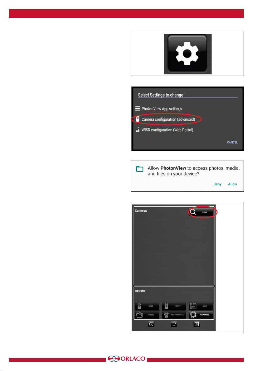
Tap the main view screen to open the on-screen
menu and tap the Configuration icon, figure 33 and
choose ‘WISR configuration’ on the Settings Selec-
tion screen, see figure 34.
This opens a web browser and shows the WISR
Configuration portal, see figure 35, tap the User field
and select ‘Administrator’, see figure 36, then tap
Password and enter the administrator password,
then tap ‘Sign in’.
The WISR portal holds 2 user accounts:
• Administrator with full access, the password is
‘usethisportalwise’. See figure 37.
• User with restricted access, the password is
‘user’.
The WISR Portal, see figure 38, shows a tabbed
screen with 7 tabs. Here is a brief description of the
default configuration and who can do what on each
tab.
Remember that after changing values on a tab, tap
the Apply button to store them or Undo to discard
the changes.
Status, this is a summary of the important items
on the WiFi and Network tabs, the last line shows
the installed Firmware version.
WiFi, the default factory WiFi configuration is,
Country: US,
Bandwidth: 40 MHz (model 0300100) or 20 MHz
(model 0300150),
Channel: auto (5.8GHz) (model 0300100) or auto
(2.4GHz) (model 0300150),
Power: 14 (model 0300100) or 20 (model
0300150),
SSID: WISR-UNCONFIGURED,
Password: orlacowireless.
Normally you only need to alter the Country, the
WiFi name (SSID) and the Password.
This can be done by both the Administrator and
User accounts. The Password field contains the
‘eye’ button to show or hide the password.
Network, the default factory Network configuration
is Mode: AP only/Stand-alone. The IP and MAC
Addresses are fixed and cannot be altered.
The ‘normal’ use case would be the AP only/
Figure 34
Figure 36
Figure 35
Figure 33
Figure 37

11
User manual
UM0972260 A 07
Stand-alone mode, this allows the use of a tablet
connected to 1 WISR. The WISR can be wired to
1 or 2 EMOS cameras.
Another use (see chapter 2) would be connecting
2 WISRs together, allowing for up to 4 EMOS
cameras. This can be done by both the Adminis-
trator and User accounts.
The ‘AP + Interlink’ and ‘Local + Interlink’ modes
should not be used in this system setup.
Vehicle, the default factory Vehicle configuration
is Vehicle capabilities: only Direction info and
Speed limit: 25 km/h. The WISR can be con-
nected to the vehicle by a total of six wires, the information conveyed on these wires can be interpreted
by the PhotonView app.
The wires are marked as follows:
C1 blue Left direction
C2 brown Right direction
C3 white/yellow Forward direction
C4 green Reverse direction
Aux1 grey Tacho pulses (speed)
Aux2 yellow Handbrake
The priority of the C1...4 wires is that C1 has the highest priority and C4 the lowest.
PhotonView (see chapter 1.4) is able to display a view for each of the C1 to C4 wires. A view can consist
of up to 4 cameras shown on the screen.
The Tacho/Handbrake signals can be used to inhibit the use of the menu when the vehicle is moving.
The configuration here is mainly for the Administrator account.
When the WISR system is deployed with an HD-E/AFZ or HD-E/PTZ camera, these wires are used for Pan,
Tilt and Zoom operations.
Camera, the stand-alone or local WISR holds the camera configuration. In this section the administrator
must configure the connected cameras, the fields are for camera type, IP mode and mirroring. Para-
graph 1.2.1 describes in detail how to do this.
Firmware, the firmware can be updated Over-The-Air or by connecting the WISR to a PC. A newer version
will be distributed together with the PhotonView app from the Orlaco download site. Firmware updates
can be done by the Administrator only. See chapter 1.4. WISR firmware update, page 10.
Users, the default factory configuration has 2 accounts, Administrator and User, the passwords are
mentioned above. The Administrator is able to alter both Administrator and User passwords as well as
the User rights.
User rights are default set to Wifi settings only. The User is only able to alter the User password.
Features,these checkboxes determine what Network modes can be selected. Currently all modes are
selectable. The Channel ranges are fixed to the model number, 5.8 GHz for 0300100 and 2.4 GHz for
0300150. Only the Administrator is able to alter these settings.
Figure 38

12
User manual
UM0972260 A 07
1.4 WISR rmware update
The WISR firmware needs to be updated when the
installed version of the PhotonView app detects when
the version of the connected WISR does not match
the version of the app.
PhotonView displays a message like Figure 39 on
the top-center of the screen.
WARNING! Never turn the power of
the WISR OFF when performing a
FLASH operation!
Updating the WISR is a multi-step process, first
perform the firmware update:
1. Open the main menu and go to the ‘WISR
configuration (Web Portal)’, if the message as
in Figure 40 appears, tap ‘Allow’.
2. In the browser on the ‘WISR Web portal, log-in
as Administrator; see paragraph 1.3. page 8.
3. When logged-in, the current Firmware version
is shown on the Status tab.
4. Select the Firmware tab.
5. After flashing firmware, the configuration set-
tings are set to default values. The settings can
be saved before flashing (Export) and restored
after flashing (Import) by using the Export/
Import buttons, see Figure 41.
6. Select the Firmware tab and tap the Open
button, tap on the blue ‘Files’ file browser
button, see Figure 42.
7. Select the firmware (.wisr file) from the root map
of the tablet. Depending on the tablet, start with
‘Galaxy Tab S3’ or ‘ET51’ and then ->
Photonview -> Firmware -> WISR.
8. Tap the ‘Apply’ button to ‘flash’ the new firm
ware into the WISR, on the ‘proceed’ question
screen (Figure 43) tap on ‘Ok’, the progress bar
from Figure 44 will be shown.
9. When the update is done, the name of the WISR
will be ‘WISR-UNCONFIGURED’ with the
password ‘orlacowireless’.
10. In the PhotonView app, select the WISR
connections screen (Figure 45) and connect with
the updated WISR.
The settings of the WISR can be exported to or imported
from the tablet. Exported settings are stored in the Download folder on
the tablet. Note that when settings are imported, they must be applied
with the Apply button on the bottom of the screen. See Figure 46.
Figure 39
Figure 40
Figure 42
Figure 41
Figure 43
Figure 44
Figure 46
Figure 45

13
User manual
UM0972260 A 07
1.5. PhotonView conguration
In PhotonView from the main view screen, tap for
the on-screen menu, tap the configuration gear
icon and in the Settings selector tap on ‘Photon-
View App settings’.
In the default configuration, there is no Google
user account associated with the tablet and the
PhotonView menu is ‘open’ for every user of the
tablet.
When a Google account is set on the tablet, this
would be necessary when the user wants to down-
load a new app from the Google play store, then
this account is also able to alter all settings on the
PhotonView menu.
From top to bottom, de factory defaults for Pho-
tonView are shown here.
User Interface, Theme: Brushed Metal, View
Mode: Quad camera to show all possible attached
cameras and Picture Stretch: is enabled.
The View Mode can be set to a single camera to
show one of possible four attached cameras. When
Front/Rear (camera 1 and 3), Rear/Rear (camera
2 and 4) or Left/Right (camera 1 and 2) view is
selected, the main view screens show only the 2
cameras as indicated. The last option is Vehicle
Direction and that enables the tablet to display a
view according to the switch wire inputs on the
WISR. Note that this feature must be enabled on
the WISR portal setting.
Device: Network interface: Auto →leave this on
Auto.
Nearby WISR selection: Manual only →leave this
on Manual only.
When the connection was lost it will automatically
reconnect without asking.
Camera settings: A number of functions can be
configured for each possible EMOS camera. Tap
on one of the Cameras 1 to 4 and a corresponding
menu opens, see figure 47.
When Connected is off, this camera will not be
shown, Caption is just a name for the user it is not
shown on the screen, Mirroring can be used to
Figure 47

14
User manual
UM0972260 A 07
show the camera in a Normal, Mirrored, Flipped or
Mirrored and Flipped way. This setting will override
the current EMOS camera setting.
The fields Command IP must be the same as in the
Camera config for ‘Connection, Camera IP’, Com-
mand Port must be the same as in the Camera
config for ‘Connection, Camera Port’ and must be
in the 192.168.40.xx subnet and Video Port must
be the same as in the Camera config for ‘Stream,
Stream Port’.
Remark: In this menu when a field is changed,
use the Next button on the on-screen keyboard
until Done is tapped, then the OK button must be
tapped to store the values.
Camera presets, these settings, see figure 48, de-
pend on the View Mode setting. When View Mode
is set to Single camera, the Single camera preset
selects which camera and how it is presented. All
other Camera presets are valid when View Mode
is set to Vehicle Direction. Note that for Vehicle
Direction mode, the Vehicle settings WISR portal
must also be enabled. This presets feature is dis-
abled in model number 0300150 (WISR LR) and
also when in model 0300100 (WISR) the HD-E/
AFZ or HD-E/PTZ camera is used.
Streams, these settings are for ‘tweaking’ the sys-
tem, normally you should leave them in the default
configuration.
Adaptive streaming, when set to ON the effect
of dropped frames due to the WiFi is much less
noticeable.
General frame rate, the system will try to send
frames at the desired framerate. Setting this to a
lower FPS decreases the data throughput and can
have effect on the distance between WISRs and tablet.
Stream frame injection, normally not used.
Stream bitrate scale, used to minimize network traffic, select 25%, 50%, 75% or 100% of the bitrate the
system chooses. The 100% bitrate will be 50 Mbps for full screen (large), 20 Mbps for 2 streams on the
screen (medium) and 13 Mbps for a quad screen view (small).
NB. The total bitrate of all streaming cameras must not exceed 50 Mbps.
PTZ, the Zooming speed (Zoom part of HD-E/AFZ or HD-E/PTZ) and Moving speed (Pan and Tilt part of
HD-E/PTZ) are default set to 75%. This can be adjusted to 25%, 50%, 75% and 100%.
Figure 48

15
User manual
UM0972260 A 07
2. Local/Remote WISR setup
In chapter 4, page 17, an overview sketch is shown
of a 4-camera system.
In a 4-camera system, there are 2 WISRs where
each WISR is connected to 2 EMOS cameras. The
tablet communicates with the 2 WISRs and is able
to show up to 4 video streams.
This part of the manual uses the ‘local’ and
‘remote’ terms, here ‘local’ means the WISR that is
closest to the tablet and ‘remote’ is the WISR that
is farther away.
This chapter describes the setup of the tablet, local
and remote WISRs and the 4 EMOS cameras.
2.1. Naming the WISRs
First, handle the WISRs one by one. When a WISR
is powered on for the first time, it shows a default
factory network name.
This SSID is ‘WISR-UNCONFIGURED’ and the
password is ‘orlacowireless’. Change the name and
password of this WISR to the name and password
you want for the remote WISR. Refer to Chapter
1.3. on how to do this.
After the name/password has been changed and
applied, power down the WISR.
In this example, the remote WISR will be con-
nected to cameras 3and 4. They will be displayed
on the tablet in the lower part of the quad screen.
The lower left will be camera 3and the lower right
will be camera 4.
Power up the second WISR and change the name
and password of this WISR to what you want for
the local WISR. Refer to Chapter 1.3. on how to do
this. After the name/password has been changed
and applied, power down the WISR.
In this example, the local WISR will be connected
to cameras 1and 2.
They will be displayed on the tablet in the upper
part of the quad screen.
Upper left will be camera 1and upper right will be
camera 2.
Figure 49
Connect the cameras to the WISRs and power
everything up.
On the tablet start PhotonView and go to the WiFi
selection screen. In this example, the WISRs are
named ‘Local-1’ and ‘Remote-1’ and the WiFi
selection screen looks like figure 49.

16
User manual
UM0972260 A 07
2.2. Remote WISR setup
These instructions configure the cameras of the
remote WISR to be displayed in the lower part of
the quad screen. The lower left will be camera 3
and the lower right will be camera 4.
Bring the main menu up again and go to the WISR
configuration.
Log in as Administrator, the default password is
‘usethisportalwise’.
When logged in, go to the Network tab and change
the Mode to ‘Remote / Trailer’, then enter a four
digit value in the Pairing PIN textbox, see figure
50, and tap the Apply button.
A pop-up is shown, showing that these settings
are being applied, see figure 51. Refer to figure
45 for the Feature settings to enable the Local and
Remote Network modes.
Go back to PhotonView by tapping a few times on
the tablet Back button.
Select the quad-view and when the WISR is ready
again the 2 cameras of the remote WISR should be
on screen, see figure 52.
Figure 51
Figure 50
Figure 52
CAM 3 CAM 4

17
User manual
UM0972260 A 07
Figure 54
Figure 55
Figure 53
Figure 56
CAM 3 CAM 4
CAM 1 CAM 2
2.3 Local WISR setup
These instructions are like the ones in the previous
chapter, except that the cameras of the local WISR
will be displayed in the upper part of the quad
screen. Upper left will be camera 1and upper right
will be camera 2.
Bring the main menu up again and go to the WISR
configuration.
Log in as Administrator, the default password is
‘usethisportalwise’.
When logged in, go to the Network tab and change
the Mode to ‘Local / Cabin’ and tap the Scan but-
ton, see figure 54 and tap the Apply button.
A pop-up is shown, showing that these settings
are being applied, see figure 54. Refer to figure
53 for the Feature settings to enable the Local and
Remote Network modes.
A pop-up screen will be displayed with the remote
WISR, see figure 55, tap on the line that contains
the remote WISR. The Interlink SSID will be filled
in automatically, supply the Password value as in
the remote WISR and tap the Apply button.
A pop-up is shown, showing that these settings
are being applied, see figure 51.
Go back to PhotonView by tapping a few times on
the tablet’s Back button.
Select the quad-view and when the WISR is ready
again all 4 cameras should be on screen, see figure
56.

18
User manual
UM0972260 A 07
Figure 57
Figure 58
Figure 60
Figure 59
3. Troubleshooting guide.
3.1. Your WISR is not on the WISR connections
screen
On the WISR connections screen, a list of WISRs
will be visible. If ‘your’ WISR is not on the list, tap
the Search button, see figure 57, to refresh the
screen and show all WISRs that are in range.
It happens that your WISR is still not on the list or
that the app complains about ‘too many requests’
or that the search ‘takes too long’.
In this case tap the ‘Recent apps’ button, see figure
58 and then tap ‘Close all’, see figure 59.
Then swipe down from the top of the screen and
tap-and-hold the WiFi button, see figure 60.
Wait a moment for all Wireless Access Points in
range to show up on the list and select your WISR.
3.2. Web portal, Sign in
When connected by WiFi to a WISR, the web
browser can be used to configure the WISR.
In the address bar of the browser you normally
type in a URL or an IP address.
Notice the text in blue underneath the User/Pass-
word Sign in window. Tapping the blue text con-
nects to the WISR on a different URL (address).
This has the same effect as typing ‘local.wisr’ or
‘remote.wisr’ on the address bar.
Note: local.wisr resolves to 192.168.40.1 and
remote.wisr to 192.168.40.2, you can use that too.
3.3. It takes a longer time to start-up
Normal startup behavior of the WISR system is
that after Power-on it will take about one-and-a-
half minutes to display the camera stream on the
tablet.
In the case that the Remote WISR is switched off
for a period shorter than three minutes, it will take
about five minutes to start up.

19
User manual
UM0972260 A 07
WISR router
Wi-Fi®
WISR router local
Wi-Fi
WISR router remote
Wi-Fi®
®
Camera EMOS EthernetCamera EMOS Ethernet
Power
Power
Power
Power
Power
Power
Power
Power
Power
Tablet
Tablet
Extension
cable
Extension
cable
Extension
cable
2 camera system
This configuration is valid only for WISR SR system.
4 camera system
4. System overview

20
User manual
UM0972260 A 07
Application of the WISR Long Range system
WISR router local
Wi-Fi
®
Foot switch
Art. No. 0502630
Power supply
Art. No. 0503810
230V
System overview WISR LR Cabin
Auto contact
Art. No. 0405951
Battery Pack
Art. No. 0049040
System overview WISR LR Trolley
WISR router remote
Camera AFZ HD-E
Camera
EMOS Ethernet
Wi-Fi
®
1 x 8p Male input
3 x 8p Female output
To be designed.
Cable Ethernet
Cable Ethernet
Power extension cable(To be designed).
Camera
EMOS Ethernet
Camera
EMOS Ethernet
Power extension cable(To be designed).
Tablet
8p male
8p male
1 x 8p Male input
3 x 8p Female output
To be designed.
Auto contact
Art. No. 0405951
Cable Ethernet
8p male
6p male
6p female
Spider cable
Art. No. 0403880
Wi-Fi
®
This manual suits for next models
3
Table of contents
Other Orlaco Automobile Accessories manuals
Popular Automobile Accessories manuals by other brands

HAUL MASTER
HAUL MASTER 93341 Assembly and operating instructions

Thule
Thule 1229 instructions

Fab Fours
Fab Fours GR1005 installation instructions

SuperATV
SuperATV IN-RRK-P-RZR1K installation instructions

E&G Classics
E&G Classics Black Ice Mesh instruction manual

INNO
INNO Cargo Box installation instructions