6 | Ottobock 3R95, 3R95=1
2.2.3 Einsatzbedingungen
Empfohlen vor allem für Oberschenkelamputierte, die aktiv zur Standphasensicherung beitragen
können und eine harmonische Schwungphasensteuerung wünschen. Das leichte Gewicht und
die geringe Bauhöhe sind besondere Vorteile bei der Versorgung von Frauen und Jugendlichen.
Die Modular-Leichtkniegelenke 3R95 und 3R95=1 wurden für Alltagsaktivitäten entwickelt und
dürfen nicht für außergewöhnliche Tätigkeiten wie zum Beispiel Extremsportarten (Freiklettern,
Paragleiten, etc.) eingesetzt werden.
2.3 Sicherheitshinweise
2.3.1 Allgemeine Sicherheitshinweise
• Die Modular-Leichtkniegelenke 3R95 und 3R95=1 dürfen nicht für Badeprothesen verwendet
werden.
• Beachten Sie die angegebenen Anzugsmomente.
•
Unterweisen Sie den Patienten in der sachgemäßen Handhabung des Modular-Leichtkniegelenks
lt. nachfolgendem Kapitel 2.3.2 „Patientenhinweise“.
2.3.2 Patientenhinweise
•
Das Modular-Leichtkniegelenk sollte keinem intensiven Rauch oder Staub, keinen mechanischen
Vibrationen oder Stößen und keiner großen Hitze ausgesetzt werden.
•
Achten Sie darauf, dass weder feste Teilchen noch Flüssigkeit in das Modular-Leichtkniege-
lenk eindringen können. Vermeiden Sie es, Prothesenpassteile Umgebungen auszusetzen, die
Korrosionen an den Metallteilen auslösen, z.B. Süßwasser, Salzwasser, Säuren und andere
Flüssigkeiten. Bei Einsatz des Medizinproduktes unter diesen Umgebungsbedingungen erlö-
schen alle Ersatzansprüche gegen die Otto Bock HealthCare GmbH.
•
Das Öffnen und Reparieren des Modular-Leichtkniegelenks bzw. das Instandsetzen beschä-
digter Komponenten darf nur durch den zertizierten Ottobock Service vorgenommen werden.
•
Je nach Umgebungs- und Einsatzbedingungen kann die Funktion des Kniegelenks beeinträchtigt
werden. Um eine Gefährdung des Patienten zu vermeiden, darf das Kniegelenk nach spürbaren
Funktionsveränderungen nicht weiter benutzt werden. Diese spürbaren Funktionsveränderungen
können sich z.B. als Schwergängigkeit, unvollständige Streckung, nachlassende Schwungpha-
sensteuerung bzw. Standphasenunsicherheit, Geräuschentwicklung, etc. bemerkbar machen.
Falls Sie eine Beschädigung oder eine spürbare Funktionsveränderung bemerken, suchen Sie
bitte eine Fachwerkstatt zur Überprüfung der Prothese auf.
2.4 Qualikation des Orthopädie-Technikers
Die Versorgung eines Patienten mit den Modular-Leichtkniegelenken 3R95 und 3R95=1 darf nur
von Orthopädie-Technikern vorgenommen werden.
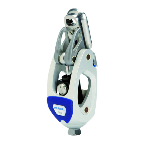
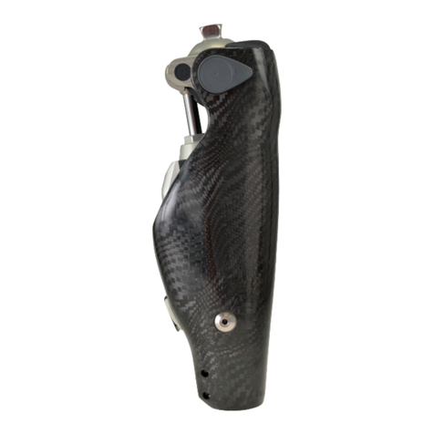
2.5 Konstruktion und Funktion (Abb. 1)
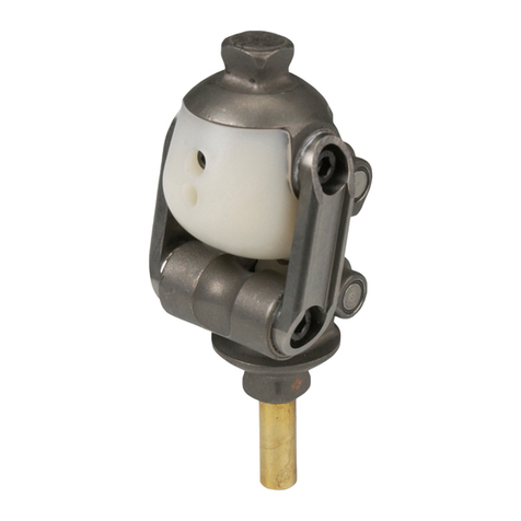
Gelenkober- und Gelenkunterteil sind aus Leichtmetall gefertigt und durch eine spezielle Achstechnik
miteinander verbunden. Zur Steuerung der Schwungphase ist in den Gelenkkörper eine Hydraulik
in Kleinstbauweise integriert. Sie dient der Erzeugung von dynamischen Bewegungswiderständen,
die das Gangbild optimieren, indem sie ein zu weites Durchschwingen in der Beugung und ein zu
hartes Anschlagen in der Streckung verhindern.
Der Bewegungswiderstand (Dämpfungsverhalten) ist durch Verstellen des Durchussquerschnittes
regulierbar. Dabei können Beuge-und Streckbewegung unabhängig voneinander eingestellt werden.
•
Die Gestaltung der Anlenkgeometrie der Hydraulik ergibt auch bei großer Beugung noch einen
hohen Beugewiderstand.
