OVE NIKO 48 User manual

PAGE 1
NIKO 48
INSTALLATION MANUAL | MANUEL D’INSTALLATION | MANUAL DE INSTALACIÓN
Questions, problems, need help?
Call our customer service department at
1-866-839-2888, 8 a.m. - 5 p.m., EST, Monday - Friday
Questions, problèmes ou besoin d’aide?
Contactez notre service à la clientèle au
1-866-839-2888, du lundi au vendredi de 8 h à 17 h HNE.
Preguntas, problemas o necesita ayuda?
Llame a nuestro departamento de servicio al cliente al
1-866-839-2888, 8 am. – 5 pm., HDE, Lunes a Viernes.
An installation video guide can be found on our Youtube channel:
Un guide d’installation video est disponible sur notre chaîne Youtube:
Una guía de instalación de vídeo está disponible en nuestro canal de Youtube:
https://tinyurl.com/3y33u3dr
Satin Nickel / Satiné / Satinado: ITEM / ARTICLE / ARTÍCULO #3492202
Matt Black / Noir Mat / Negro Mate: ITEM / ARTICLE / ARTÍCULO #3492206

PAGE 2
TABLE OF CONTENT
TABLE DES MATIÈRES
TABLA DE CONTENIDOS
TABLE OF CONTENT ........................................2
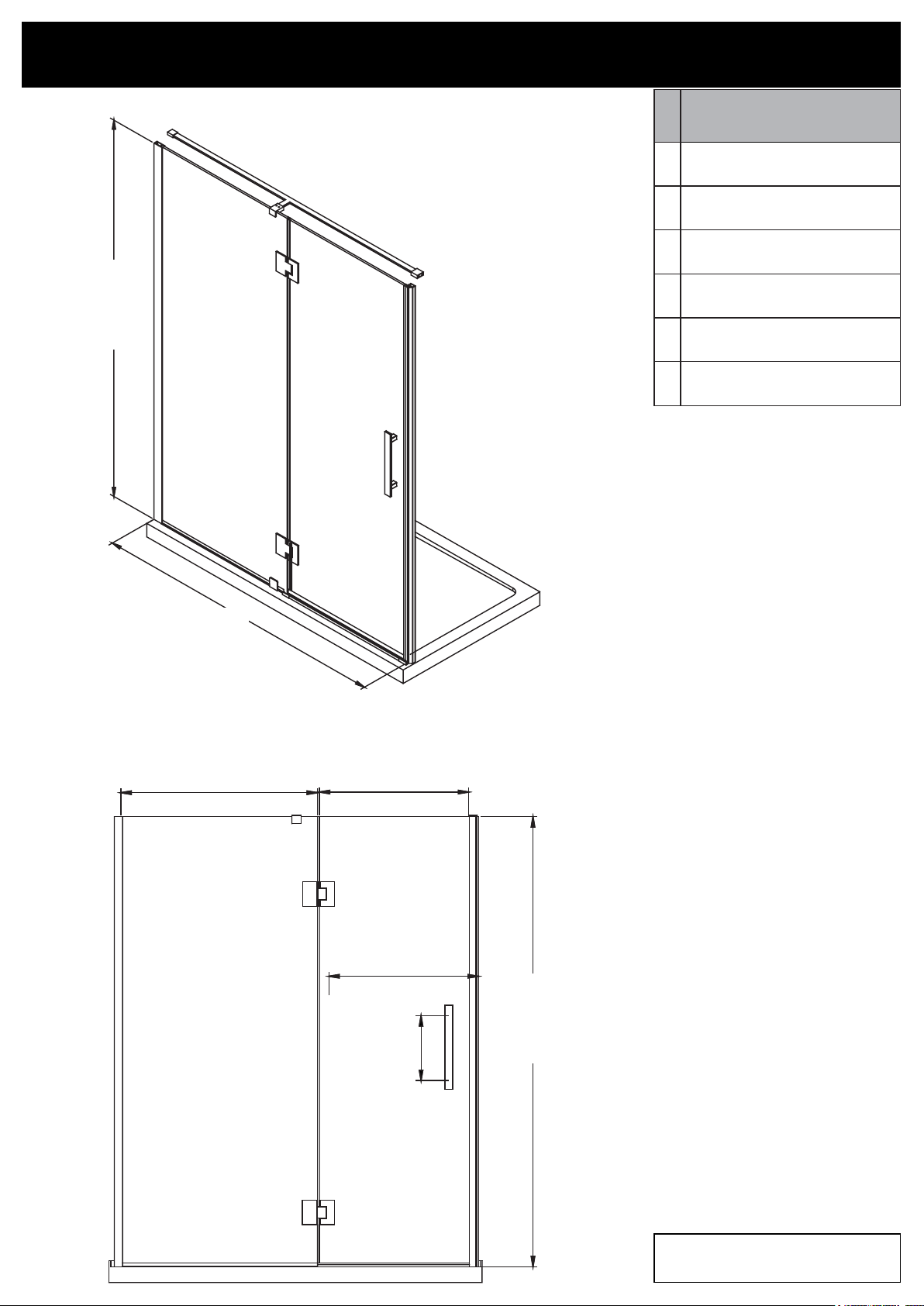
SHOWER DIMENSIONS.....................................3
WALL-TO-WALL DIMENSIONS..........................4
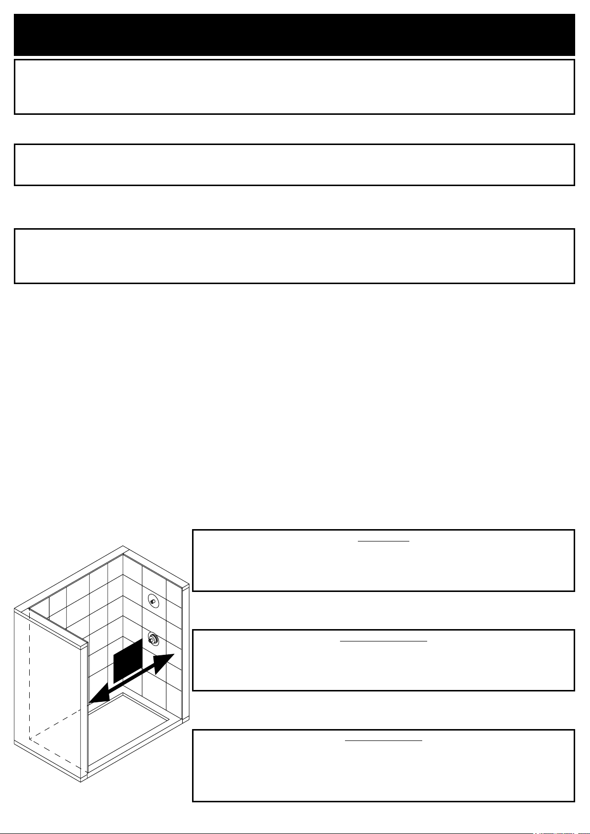
INSTALLATION STRUCTURE OVERVIEW .......5
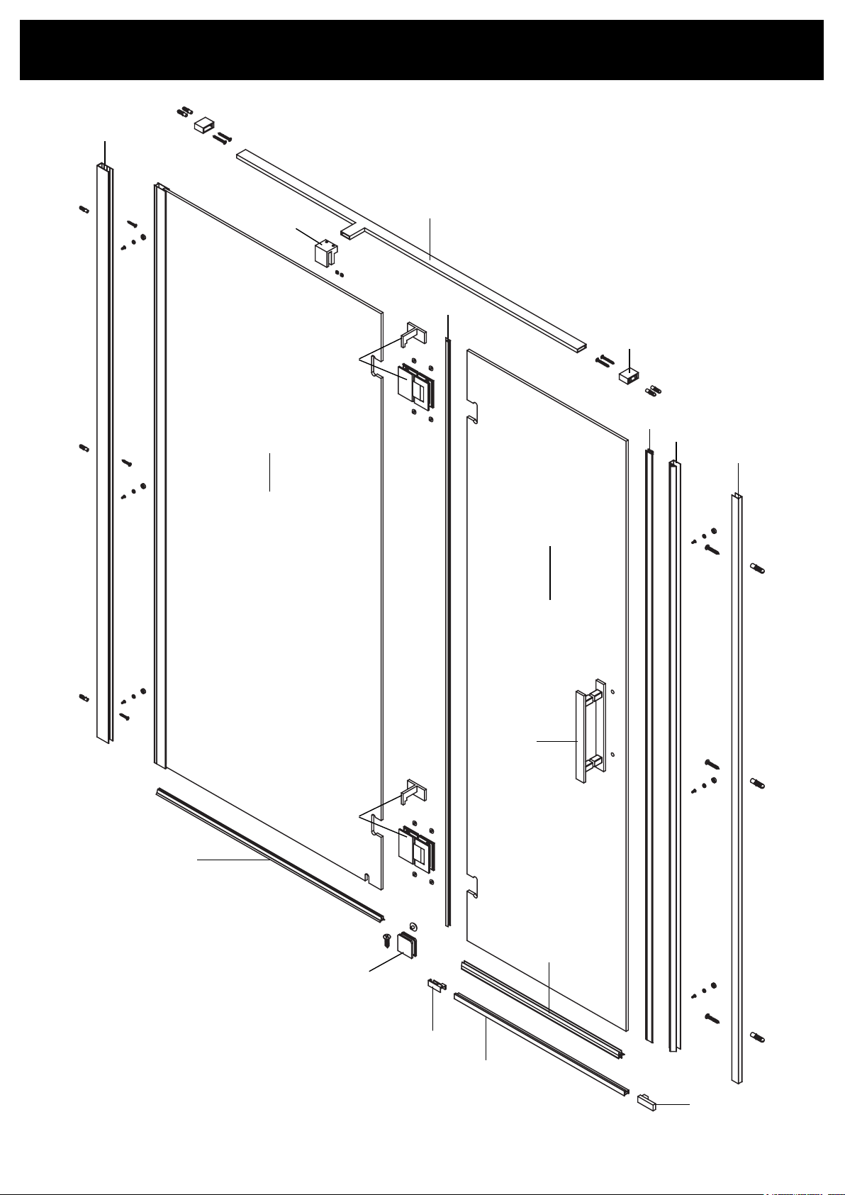
PACKAGE CONTENT ........................................6
PART LIST ..........................................................8
SUPPLIED HARDWARE LIST..........................10
TOOLS REQUIRED (not supplied) .................10
PREPARATION................................................. 11
SAFETY INFORMATION ..................................12
SAFETY NOTICE..............................................13
PREPARATION.................................................13
WALL TRACK INSTALLATION........................14
FIXED PANEL INSTALLATION.........................15
SHOWER DOOR INSTALLATION....................17
CLAMP INSTALLATION...................................22
DECORATIVE TRACK INSTALLATION...........24
SUPPORT BAR INSTALLATION .....................25
WALL TRACK FASTENING .............................28
SEALING ..........................................................29
MAINTENANCE AND CARE ............................30
LIMITED PRODUCT WARRANTY....................31
TABLE DES MATIÈRES .....................................2
DIMENSIONS DE LA DOUCHE .........................3
MESURES MUR-À-MUR.....................................4
VUE D’ENSEMBLE DE LA STRUCTURE
D’INSTALLATION ..............................................5
CONTENU DE L’EMBALLAGE .........................6
LISTE DES PIÈCES............................................8
QUINCAILLERIE FOURNIE ............................10
OUTILS REQUIS (non fournis).........................10
PRÉPARATION ................................................ 11
INFORMATION SUR LA SÉCURITÉ................12
AVIS DE SÉCURITÉ ........................................13
PRÉPARATION ................................................13
INSTALLATION DE LA GLISSIÈRE ................14
INSTALLATION DU PANNEAU FIXE ...............15
INSTALLATION DE LA PORTE DE DOUCHE.17
INSTALLATION DES PINCES..........................22
INSTALLATION DE LA RAIL DÉCORATIF......24
INSTALLATION DE LA BARRE DE SOUTIEN
..........................................................................25
FIXATION DU RAIL MURAL ............................28
SCELLAGE.......................................................29
ENTRETIEN ET MAINTENANCE.....................30
GARANTIE LIMITÉE DU PRODUIT .................31
TABLA DE CONTENIDOS..................................2
DIMENSIONES DE LA DUCHA..........................3
MEDIDAS DE PARED-A-PARED........................4
VISIÓN GENERAL DE LA ESTRUCTURA DE
INSTALACIÓN ...................................................5
CONTENIDO DEL PAQUETE.............................6
LISTA DE PIEZAS...............................................8
CONTENIDO DE HARDWARE.........................10
HERRAMIENTAS NECESARIAS (no incluido) ..
...........................................................................10
PREPARACIÓN ................................................ 11
INFORMACIÓN DE SEGURIDAD ....................12
AVISOS DE SEGURIDAD.................................13
PREPARACIÓN ................................................13
INSTALACIÓN DEL RIEL DE PARED..............14
INSTALACIÓN DEL PANEL FIJO.....................15
INSTALACION DE LA PUERTA DE DUCHA ...17
INSTALACION DE LA ABRAZADERA ............22
INSTALACIÓN DE LA RIEL DECORATIVO.....24
INSTALACIÓN DE LA BARRA DE APOYO ....25
FIJACIÓN DEL CARRIL DE LA PARED ..........28
SELLADO .........................................................29
MANTENIMIENTO Y CUIDADO .......................30
GARANTÍA LIMITADA DEL PRODUCTO ........31

PAGE 3
SHOWER DIMENSIONS
DIMENSIONS DE LA DOUCHE
DIMENSIONES DE LA DUCHA
Measures: inch [millimeter]
Mesures: pouce [millimètre]
Medidas: pulgadas [milímetros]
Measurements
Mesures
Medidas
A
Shower height
Hauteur de la douche
Altura de la ducha
B
Shower width
Largeur de la douche
Ancho de la ducha
C
Fixed panel width
Largeur du panneau xe
Ancho de panel jo
D
Door panel width
Largeur de la porte
Anchura del panel de la puerta
E
Door opening
Ouverture de la porte
Abertura de la puerta
F
Distance between handle holes
Distance entre les trous de poignée
Distancia entre los oricios de la manija
A
73 7/8” [1877]
*B*
46 1/4” [1174]
C
21 9/16” [548]
D
23 1/4” [590]
E
22 5/8” [575]
F
13 3/4” [350]
A
73 7/8” [1877]

PAGE 4
D
WALL-TO-WALL DIMENSIONS
MESURES MUR-À-MUR
MEDIDAS DE PARED-A-PARED
• Make sure to have a distance tile to tile (D) between 46 1/4 in (1174mm) min. and 48 in (1219mm) max. (see
image).
• Measure the thickness of your tiles on either side before installing the metal tracks. A thicker tile will limit your space
to install the shower panels.
• Assurez vous d’avoir une distance tuile à tuile entre 46 1/4 po (1174mm) min. et 48 po (1219mm) max. (voir image).
• Mesurez l’épaisseur de vos tuiles sur chacun des côtés avant d’installer le rail mural. Une tuile plus épaisse limitera
l’espace requis pour installer votre douche.
• Asegúrese de tener una distancia baldosa a baldosa entre 46 1/4 pulg. (1174mm) Min y 48 pulg. (1219mm) Max
(ver imagen).
• Mida el espesor de las baldosas antes de instalar los rieles metálicos. Una baldosa más espesa limitará el espacio
para instalar los paneles de la ducha.
WARNING!
Make sure to have a distance (D) from the left side tile to the right side tile:
D Min = 46 1/4 in (1174mm)
D Max = 48 in (1219mm)
AVERTISSEMENT!
Assurez vous d”avoir une distance (D) de la tuile droite à la tuile gauche de:
D Min = 46 1/4 po (1174mm)
D Max: 48 po (1219mm)
¡ADVERTENCIA!
Asegúrese de tener una distancia (D) de baldosas en el lado izquierdo de la teja en el lado
derecho:
D Min: 46 1/4 pu (1174mm)
D Max: 48 pu (1219mm)

PAGE 5
INSTALLATION STRUCTURE OVERVIEW
VUE D’ENSEMBLE DE LA STRUCTURE D’INSTALLATION
VISIÓN GENERAL DE LA ESTRUCTURA DE INSTALACIÓN
1. Before you start the installation of your product consult the illustration 1 below showing a side-view of the completed installation.
2. Illustration 2 shows the recommended wall structure and measurements for the product installation.
NOTE: Customer must follow and comply with the local and national building and plumbing codes. All illustrations in this manual are for reference
only and do not take precedent on any code or regulation. This product should be installed by a professional.
1. Avant de commencer l’installation de votre produit, consultez l’illustration 1 ci-dessous montrant une vue latérale de l’installation terminée.
2. L’illustration 2 montre la structure de paroi recommandée et les mesures pour l’installation du produit.
REMARQUE: Le client doit suivre et se conformer scrupuleusement aux codes locaux et nationaux de construction et de plomberie. Toutes les
illustrations de ce manuel ne sont faites que pour référence et ne prennent aucun précédent sur aucun code ou règlement. Ce produit doit être
installé par un professionnel.
1. Antes de iniciar la instalación del producto, ver Figura 1 muestra una vista lateral de la instalación se haya completado.
2. La gura 2 muestra la estructura de la pared recomendado y medidas para la instalación del producto.
NOTA: El cliente debe seguir y cumplir con los códigos de construcción locales y nacionales y fontanería. Todas las ilustraciones de este manual
son indicativos y se comprometen ningún precedente para cualquier código o reglamento. Este producto debe ser instalado por un profesional.
Drywall
Placoplâtre
Paneles de yeso
Stud
Montant
Soportes
Shower base
Base de douche
Plato de ducha
Cement
Ciment
Cemento
Drain
Drain
Desagüe Waste pipe
Tuyau d’évacuation
Tubería de desagüe
Stud
Montant
Soportes
Finished Wall (tiles or other)
Mur ni
Pared terminada
FAQ
Q: What thickness of cement must I apply?
A: Between 25 mm and 38 mm (1 in and 1.5 in).
Q: Is the base installed on the studs or on the drywall?
A: On the studs.
FAQ
Q: Quelle épaisseur de ciment dois-je appliquer ?
R: Entre 25 mm et 38 mm (1 po et 1.5 po).
Q: La base est-elle installée sur les montants ou sur les murs de
placoplâtre?
R: Sur les montants muraux.
FAQ
P: ¿Qué espesor de cemento debo aplicar?
R: Entre 25 mm y 38 mm (1 pu y 1.5 pu).
P: ¿Está instalada la base en los soportes o en el panel de yeso?
R: En los soportes.
1
248” [1219]
47” [1193]
1/2” [13]
31 1/2” [800]
32” [813]
Drywall
Placoplâtre
Paneles de yeso
Stud
Montant
Soportes
32” [813]

PAGE 6
PACKAGE CONTENT
CONTENU DE L’EMBALLAGE
CONTENIDO DEL PAQUETE
Q
P
C
G
I
B
H
D
M
A
O
F
K2
L
J
E
N
R
K1

PAGE 7
PACKAGE CONTENT
CONTENU DE L’EMBALLAGE
CONTENIDO DEL PAQUETE
B
x1
C
x1
D
1x
G
1x
I
2x
J
1x
E
1x
L
1x
K1
1x
A
1x
M
1x
F
1x
H
1x
Q
1x
N
1+1
P
1+1
O
1x
R
1x
K2
1x

PAGE 8
PART LIST
LISTE DES PIÈCES
LISTA DE PIEZAS
PART #
# DE PIÈCE
PARTE #
DESCRIPTION
DESCRIPTION
DESCRIPCIÓN
QUANTITY
QUANTITÉ
CANTIDAD
CODE
CODE
CÓDIO
A
Fixed panel bottom seal strip
Bande d’étanchéité du bas du panneau xe
Tira de sello en parte inferior del panel jo
1Transparent / Transparent / Transparente: 99SRU3755-WM
Matte Black / Noir Mat / Negro Mate: 99SRU3770-WM
B
Wall track
Glissière
Riel de la pared
1
Satin Nickel / Satiné / Satinado: 99STR3821-WM
Matte Black / Noir Mat / Negro Mate: 99STR3822-WM
Chrome / Chrome / Cromo: 99STR3925-WM
C
Fixed panel
Panneau xe
Panel jo
1
Satin Nickel / Satiné / Satinado: 99SG4004-WM
Matte Black / Noir Mat / Negro Mate: 99SG4005-WM
Chrome / Chrome / Cromo: 99SG4049-WM
D
Door panel
Porte de douche
Puerta de la ducha
1 99SGD3682-WM
E
Glass panel clamp
Attache de soutien des panneaux de verre
Mordazas para paneles de vidrio
1
Satin Nickel / Satiné / Satinado: 99SGC1070-WM
Matte Black / Noir Mat / Negro Mate: 99SGC4140-WM
Chrome / Chrome / Cromo: 99SGC1044-WM
F
Door bottom seal strip
Bande d’étanchéité du bas de la porte
Tira de sello inferior de la puerta
1Transparent / Transparent / Transparente: 99SRU3756-WM
Matte Black / Noir Mat / Negro Mate: 99SRU3771-WM
G
Support bar xed panel bracket
Raccord de la barre de support pour panneau xe
Soporte de la barra ja del panel
1
Satin Nickel / Satiné / Satinado: 99SGC4155-WM
Matte Black / Noir Mat / Negro Mate: 99SGC4156-WM
Chrome / Chrome / Cromo: 99SGC2030-WM
H
Support bar
Barre de support
Barra de soporte
1
Satin Nickel / Satiné / Satinado: 99SGC4149-WM
Matte Black / Noir Mat / Negro Mate: 99SGC4150-WM
Chrome / Chrome / Cromo: 99SGC4223-WM
I
Support bar anchor
Ancrage pour barre de support
Anclaje de la barra de soporte
2
Satin Nickel / Satiné / Satinado: 99SGC4143-WM
Matte Black / Noir Mat / Negro Mate: 99SGC4144-WM
Chrome / Chrome / Cromo: 99SGC4220-WM
J
Magnetic strip
Bande magnétique
Banda magnética
1Transparent / Transparent / Transparente: 99SRU3748-WM
Matte Black / Noir Mat / Negro Mate: 99SRU3768-WM

PAGE 9
PART LIST
LISTE DES PIÈCES
LISTA DE PIEZAS
PART #
# DE PIÈCE
PARTE #
DESCRIPTION
DESCRIPTION
DESCRIPCIÓN
QUANTITY
QUANTITÉ
CANTIDAD
CODE
CODE
CÓDIO
K1
Soft close door hinge (with its clasp tool)
Charnière de porte à fermeture douce (avec son outil de fermeture)
Bisagra de puerta de cierre suave (con su herramienta de cierre)
1
Satin Nickel / Satiné / Satinado: 99SHI1014-WM
Matte Black / Noir Mat / Negro Mate: 99SHI1015-WM
Chrome / Chrome / Cromo: 99SHI3811-WM
K2
Regular door hinge (with its clasp tool)
Charnière de porte normale (avec son outil de fermeture)
Bisagra de puerta normal (con su herramienta de cierre)
1
Satin Nickel / Satiné / Satinado: 99SHI1016-WM
Matte Black / Noir Mat / Negro Mate: 99SHI1017-WM
Chrome / Chrome / Cromo: 99SHI3812-WM
L
Door panel vertical seal strip
Bande d’étanchéité vertical de la porte
Tira de sello vertical de la puerta
1Transparent / Transparent / Transparente: 99SRU3757-WM
Matte Black / Noir Mat / Negro Mate: 99SRU3772-WM
M
Door handle
Poignée de porte
Manija de la puerta
1
Satin Nickel / Satiné / Satinado: 99SHA3653-WM
Matte Black / Noir Mat / Negro Mate: 99SHA3654-WM
Chrome / Chrome / Cromo: 99SHA3668-WM
N
Fixed panel support bracket
Attache de support pour panneau xe
Soporte jo para panel de soporte
1+1
Satin Nickel / Satiné / Satinado:99SGC4145-WM
Matte Black / Noir Mat / Negro Mate: 99SGC4146-WM
Chrome / Chrome / Cromo: 99SGC4221-WM
O
Decorative track
Rail décoratif
Riel decorativo
1
Satin Nickel / Satiné / Satinado: 99STR3827-WM
Matte Black / Noir Mat / Negro Mate: 99STR3828-WM
Chrome / Chrome / Cromo: 99STR3928-WM
P
Decorative cap
Embout décoratif
Capuchones decorativos
1+1
Satin Nickel / Satiné / Satinado: 99SGC4147-WM
Matte Black / Noir Mat / Negro Mate: 99SGC4148-WM
Chrome / Chrome / Cromo: 99SGC4222-WM
Q
Magnetic track
Piste magnétique
Pista magnética
1
Satin Nickel / Satiné / Satinado: 99SRU3750-WM
Matte Black / Noir Mat / Negro Mate: 99SRU3751-WM
Chrome / Chrome / Cromo: 99SRU3816-WM
R
Wall track
Glissière
Riel de la pared
1
Satin Nickel / Satiné / Satinado: 99STR3826-WM
Matte Black / Noir Mat / Negro Mate: 99STR3834-WM
Chrome / Chrome / Cromo: 99STR3927-WM
***
Complete hardware kit
Quincaillerie complete
Todo el hardware
N/A
Satin Nickel / Satiné / Satinado: 99SHW6096-WM
Matte Black / Noir Mat / Negro Mate: 99SHW6097-WM
Chrome / Chrome / Cromo: 99SHW6126-WM

PAGE 10
SUPPLIED HARDWARE LIST
QUINCAILLERIE FOURNIE
CONTENIDO DE HARDWARE
TOOLS REQUIRED (not supplied)
OUTILS REQUIS (non fournis)
HERRAMIENTAS NECESARIAS (no incluido)
Pencil
Crayon
Lápiz
Screwdriver
Tournevis
Destornillador
Drill and drill bits
Perceuse et forets
Taladro con brocas
ø1/8” (3mm) & ø5/16” (8mm)
Level
Niveau
Nivel
Measuring Tape
Ruban à mesurer
Cinta medidora
Silicone
Silicone
Silicona
Rubber mallet
Maillet en caoutchouc
Mazo de goma
Cutter
Exacto
Cuchilla
CC
BB
AA DD EE
GG
FF HH
Screw
Vis
Tornillo
ST4x12mm
6+2
Wall Anchor
Ancrage mural
Tarugo
ø8x30mm
10+2
Screw
Vis
Tornillo
ST5x30mm
6+2
Screw
Vis
Tornillo
ST5x35mm
4+1
Cap
Capuchon
Capuchón
6x
Fitting
Raccord
Accesorio
6x
Cap of xed panel bracket
Capuchon pour panneau xe
Tapa del panel jo
2x
Cap
Capuchon
Casquillo
9x
Allen key
Clé Allen
Llave Allen
2.5mm & 4mm
II
Screw
Vis
Tornillo
ST4x20mm
1+1
Safety glasses
Lunettes de Sécurité
Anteojos de seguridad
Ratchet
Clé à rochet
Llave de trinquete
5mm Bit socket
Wood block
Bloc de bois
Bloque de madera
2x
3 13/16” (97mm)

PAGE 11
A B
FAQ
Q: If the shower head is installed on the
other wall, will it leak?
A: It is possible to install your shower
head on the other side, but we strongly
recommend to install it as illustrated.
FAQ
Q: Y’aura t-il fuite si la pomme de
douche est installée sur l’autre mur?
R: Il est possible d’installer votre
pomme de douche de l’autre côté, mais
nous vous recommandons fortement de
l’installer comme illustré.
FAQ
P: ¿Habrá una fuga si la cabeza de
ducha está instalada en la otra pared?
R: Es posible instalar su cabezal
de ducha en el otro lado, pero le
recomendamos encarecidamente que
lo instale como se muestra.
PREPARATION
PRÉPARATION
PREPARACIÓN
This instruction is drawn up for a door opening from right to left (see illustration A).
For an installation for a door opening from left to right (see illustration B), use the same instructions, but switch
around the panels: mirror eect.
Utilisez ces instructions pour une ouverture de la porte de droite à gauche (illustration A).
Pour une installation de gauche à droite (illustration B), suivez ces mêmes instructions mais permuter l’emplacement
des panneaux: eet miroir.
Estas instrucciones fueron elaboradas para una abertura de puerta de derecha a izquierda (ilustración A).
Para una abertura de izquierda a derecha (ilustración B), siga estas mismas instrucciones, pero cambie el lugar
para la ubicación del riel: efecto espejo.
Install the shower head on the door’s side as shown in the illustration! This will reduce the risk of leaking.
Installez le pommeau de douche du côté de la porte tel qu’illustré, an de diminuer les risques de fuites.
¡Instale la cabeza de la ducha hacia el lado de la puerta como se muestra! Esto reducirá el riesgo de escape de
agua.

PAGE 12
CAUTION
Please carefully read the following important safety information before handling or installing this shower. There is a risk of serious injury while
handling this product. To minimize these risks, please note:
• Always wear safety glasses and gloves while handling.
• Always read and follow all the steps in the installation instructions.
• Inspect all contents and glass for damage before installation.
• Extreme caution should be taken while handling the glass during installation as the tempered glass may shatter if in contact with a hard
surface.
• Handle the tempered glass with caution! Improperly handling the glass can cause it to break suddenly in small pieces (never in pointed
fragments).
• Always take all precautions not to touch the tempered glass with any tools during the installation, or after installed.
• Do not cut or modify the tempered glass as it will shatter if cut.
• Carefully remove product from packaging and keep packaging until installation is complete.
• Inspect all parts for damage; if there is damage to the unit prior to installation, please contact customer service at the number provided in
this guide.
• Install the shower on a oor that is level and able to accommodate the weight of the unit and an occupant.
• Consult local building codes and compliance standards prior to installation and ensure conformity.
• After installation, and from time to time, check the glass for t and nish to ensure that nothing has come loose since installation.
• Keep this installation manual for future reference.
SAFETY INFORMATION
INFORMATION SUR LA SÉCURITÉ
INFORMACIÓN DE SEGURIDAD
AVERTISSEMENT
Veuillez lire attentivement les importantes consignes de sécurité suivantes avant la manutention et l’installation de cette douche. La manipulation
de ce produit présente un risque de blessure grave. Pour minimiser ces risques, veuillez prendre note de ce qui suit:
• Toujours porter des lunettes et des gants de sécurité pendant la manutention.
• Toujours lire et suivre toutes les étapes indiquées dans les instructions d’installation.
• Avant l’installation, inspecter tout le contenu et le verre pour détecter toute forme de dommages.
• Pendant l’installation, faire très attention lorsque vous manipulez les pièces en verre, car le verre trempé peut se fracasser s’il entre en
contact avec une surface dure.
• Manipulez le verre trempé avec précaution sinon il pourrait se briser en petits morceaux (jamais en fragments pointus).
• Prendre toujours toutes les précautions nécessaires pour que, pendant l’installation ou après, les outils que vous utilisez n’entrent pas en
contact avec le verre trempé.
• Ne pas couper ni modier le verre trempé, car il pourrait se briser en éclat s’il est coupé.
• Sortir le produit de son emballage avec soin et le conserver jusqu’à ce que l’installation soit complétée.
• Inspectez toutes les pièces. S’il y a des dommages sur le produit avant l’installation, veuillez communiquer avec le service à la clientèle au
numéro indiqué dans ce guide.
• Installez la douche sur un plancher au niveau et capable de supporter le produit et son utilisateur.
• Veuillez consulter le code du batiment et les normes de conformité avant l’installation du produit.
• Après l’installation, et périodiquement, vérier l’assemblage et la nition des pièces en verre, pour vous assurer qu’aucun élément ne s’est
desserré depuis l’installation.
• Conserver le présent manuel d’instruction pour consultation future.
PRECAUCIÓN
Lea cuidadosamente la siguiente información importante antes de manipular e instalar la ducha. Hay riesgo de lesiones graves mientras se
manipula el producto. Para minimizar estos riesgos, sírvase notar:
• Utilice siempre anteojos de seguridad y guantes durante la manipulación.
• Lea y siga siempre todos los pasos en las instrucciones de instalación.
• Inspeccione todo el contenido y el vidrio por daños antes de la instalación.
• Hay que prestar atención especial mientras se manipula el vidrio durante la instalación ya que el vidrio templado se puede despedazar al
contacto con una supercie dura.
• Manipule el vidrio templado con precaución! Una manipulación inadecuada del vidrio puede ocasionar que se rompa.
• Observe siempre todas las precauciones para no tocar el vidrio templado con ninguna herramienta durante ni después de la instalación.
• No corte el vidrio templado puesto que se despedazará si se corta.
• Retire con cuidado los productos de envase y embalaje mantendrá hasta que la instalación se haya completado.
• Inspeccione todas las piezas en busca de daños, si hay daños en la unidad antes de la instalación, póngase en contacto con el servicio al
cliente al teléfono que gura en esta guía.
• Instale la ducha en un piso que esté nivelado y pueda contener el peso de la unidad y de un ocupante.
• Consulte los códigos de construcción locales y normas requeridas antes de la instalación y asegúrese de cumplirlos.
• Después de la instalación, y de tiempo en tiempo, verique el ajuste el acabado del vidrio para asegurarse de que nada se ha aojado con
el tiempo.
• Guarde este manual de instalación para consulta en el futuro.

PAGE 13
NOTICE
Any modication or alteration from what is specied in this instruction manual will void any and all warranty on this
product.
The distributor is not responsible for any damage to the unit or personal property caused by improper installation. If
you disregard instructional warnings, you will void your warranty and possibly deal with water damage.
Consult the distributor’s website for any additional information or question on this product’s installation.
SAFETY NOTICE
AVIS DE SÉCURITÉ
AVISOS DE SEGURIDAD
AVIS
Toute modication ou altération apportée aux indications données dans le présent manuel d’instructions annule
toute garantie associée à ce produit.
Le distributeur n’est pas responsable pour les dommages sur le produit ou sur la personne causés par une installation
inadéquate. Si vous ne tenez pas compte des indications du manuel d’instruction, vous annulerez votre garantie et
vous vous exposerez à des dommages causés par les fuites d’eau.
Pour de plus amples renseignements sur l’installation du produit ou si vous avez des questions, veuillez consulter
le site du distributeur.
ATENCIÓN
Cualquier modicación o alteración con respecto a lo especicado en este manual de instrucción anulará toda la
garantía de este producto.
El distribuidor no se hace responsable por cualquier tipo de daño a la unidad o propiedad personal ocasionado por
una instalación inadecuada. Ignorar estas instrucciones anulará la garantía y ocasionará daños potenciales por
agua en su hogar.
Consulte el sitio web del distribuidor para cualquier información adicional o pregunta sobre la instalación de este
producto.
PREPARATION
PRÉPARATION
PREPARACIÓN
You will need at least two people to install this unit properly.
Before beginning assembly of product, make sure all parts are present. Compare parts with package contents list
and hardware contents list. If any part is missing or damaged, do not attempt to assemble the product.
2 personnes sont requises pour installer le produit correctement et sécuritairement.
Avant de commencer l’installation du produit, soyez assuré d’avoir toutes les pièces. Comparez les pièces avec les
listes fournies. S’il y a des pièces manquantes ou endommagées, ne tentez pas d’assembler le produit.
Necesitará al menos dos personas para instalar esta unidad de forma adecuada.
Antes de comenzar a ensamblar el producto, asegúrese de tener todas las piezas. Compare las piezas con la lista
del contenido del paquete y la lista de aditamentos. No intente ensamblar el producto si falta alguna pieza o si estas
están dañadas.

PAGE 14
1 5/16” [34]
WALL TRACK INSTALLATION
INSTALLATION DE LA GLISSIÈRE
INSTALACIÓN DEL RIEL DE PARED
1.1-1.2. Position the wall track (B) as illustrated. Level the track (B) and mark the track holes positions.
1.3. Remove the track and drill pilot holes in the marked locations with a ø8mm (5/16 in) drill bit.
1.4. If there are no studs located behind the wall track (B), then insert the wall anchors (AA) using a rubber mallet until the wall anchors are ush with the wall.
1.5. Replace and secure the track (B) with screws (CC). Do not overtighten.
1.1-1.2. Positionnez la glissière (B) tel qu’illustré. Mettre le rail (B) à niveau et marquer l’emplacement des trous.
1.3. Retirez la glissière et percez des trous guides aux endroits marqués avec un foret ø8mm (5/16 po).
1.4. S’il n’y a pas de montant mural derrière la glissière (B), alors insérez les ancrages muraux (AA) en utilisant un maillet en caoutchouc.
1.5. Replacez la glissière (B), puis la xer avec les vis (CC). Ne pas serrer trop fortement.
1.1-1.2. Posicionar el riel de pared (B) como se muestra. Nivele el riel (B) y marque las posiciones de los agujeros del riel.
1.3. Retire el riel y perfore los agujeros guía en los sitios marcados con una broca de ø8mm (5/16 pu).
1.4. Si no hay un soporte de pared detrás del riel de pared (B), inserte los tarugos (AA) con un mazo de goma hasta que estos queden al ras de la pared.
1.5. Vuelva a colocar y jar el riel (B) con los tornillos (CC). No los apriete excesivamente.
1
B
ø5/16”
8mm
CC
AA
1.1
1.2
1.3
1.4 1.5
1” [25]
WARNING!
If there are no studs aligned to the wall track behind
the drywall, use the wall anchors to ensure the
screws won’t become loose.
AVERTISSEMENT!
S’il n’y a pas de montants alignés derrière le mur de
placoplâtre, utilisez les ancrages muraux pour vous
assurer que les vis ne se desserreront pas.
¡ADVERTENCIA!
Si no hay vigas alineadas con el riel de pared
detrás del panel de yeso, use las anclas de
expansión para pared a n de garantizar que los
tornillos no se aojen.

PAGE 15
A
9/16”[14]
9/16”[14]
9/16”[15]
C
A
FIXED PANEL INSTALLATION
INSTALLATION DU PANNEAU FIXE
INSTALACIÓN DEL PANEL FIJO
2.1-2.2. Cut the xed panel bottom seal strip (A). Insert the xed panel bottom seal strip (A) on the base of the xed panel (C).
2.3. Insert the xed panel (C) into the wall track (B). Do not fully tighten it as further adjustments may be required.
Note: The wall track (B) allows you to adjust the position of the xed panel (C). Adjusting the depth and/or giving the glass panel a slight angle allows
for precise alignment with the door.
2.4. Insert the xed panel support bracket (N) into the xed panel (C).
2.1-2.2. Coupez la bande d’étanchéité du bas du panneau xe (A). Insérez la bande d’étanchéité du panneau xe (A) à la base du panneau xe (C).
2.3. Insérez le panneau xe (C) dans la glissière (B). Ne pas le xer car vous pourriez apporter de futurs ajustements.
Note: La glissière (B) permet d’ajuster la position du panneau xe (C). Ajustez la profondeur ou/et donner un léger angle au panneau permet d’obtenir
un alignement parfait avec la porte.
2.4. Insérez le support xe (N) dans le panneau xe (C).
2.1-2.2. Corte de la tira de sello en parte inferior del panel jo (A). Inserte la tira de sello en la parte inferior del panel jo (A) en la base del panel jo (C).
2.3. Inserte el panel jo (C) en el riel de pared (B). No lo apriete completamente ya que se puede necesitar más ajustes.
Nota: El riel de pared (B) le permiten ajustar la posición del panel jo (C). Al ajustar la profundidad y/o al mover el panel hacia un ligero ángulo se
permite una alineación precisa con la puerta.
2.4. Inserte la abrazadera de soporte del panel jo (N) en el panel jo (C).
2
2.1 2.2
B
C
2.3 2.4
C
N

PAGE 16
IMPORTANT SAFETY NOTICE BEFORE CONTINUING!
The next step of the installation will require the handling of the 2 shower door hinges. The
REGULAR hinge (K2) uses a loaded spring to propel the door, and it is extremely important to
handle the REGULAR hinge (K2) with care during installation. If the hinge aps back in place
during the installation, it will do so forcefully!
Ensure to listen to the video explaining how to safely and properly handle the 2 hinges during the
installation by following the video link at the bottom of this page.
AVIS DE SÉCURITÉ IMPORTANT AVANT DE CONTINUER !
L’étape suivante de l’installation nécessite la manipulation des 2 charnières de la porte de
douche. La charnière REGULIERE (K2) utilise un ressort chargé pour propulser la porte, et il est
extrêmement important de manipuler la charnière REGULIERE (K2) avec précaution pendant
l’installation. Si la charnière se remet en place pendant l’installation, elle le fera avec force !
Assurez-vous d’écouter la vidéo expliquant comment manipuler correctement et en toute sécurité
les 2 charnières pendant l’installation en suivant le lien vidéo au bas de cette page.
AVISO DE SEGURIDAD IMPORTANTE ANTES DE CONTINUAR
El siguiente paso de la instalación requerirá la manipulación de las 2 bisagras de la puerta de
la ducha. La bisagra REGULAR (K2) utiliza un muelle cargado para impulsar la puerta, y es
extremadamente importante manejar la bisagra REGULAR (K2) con cuidado durante la instalación.
Si la bisagra se mueve hacia atrás durante la instalación, lo hará con fuerza.
Asegúrese de escuchar el vídeo que explica cómo manipular de forma segura y adecuada las 2
bisagras durante la instalación siguiendo el enlace del vídeo al nal de esta página.
WARNING!
DO NOT pry open the REGULAR door hinge (K2) using your hands! If it rebounds and aps back, it will do so forcefully.
DO USE a wrench to open up the REGULAR hinge (K2), and ensure to protect the hinge with a soft cloth to avoid scratches.
During installation, DO USE the CLASP plastic tool supplied with the 2 hinges (K1 & K2) to keep the hinges safely opened, and prevent them from closing.
AVERTISSEMENT!
NE FAITES PAS levier pour ouvrir la charnière de porte REGULIERE (K2) avec vos mains ! Si elle rebondit et se rabat, elle le fera avec force.
UTILISEZ une clé pour ouvrir la charnière RÉGULIÈRE (K2), et veillez à protéger la charnière avec un chion doux pour éviter les rayures.
Pendant l’installation, UTILISEZ l’outil en plastique CLASP fourni avec les 2 charnières (K1 & K2) pour maintenir les charnières ouvertes en toute sécurité, et
les empêcher de se refermer.
¡ADVERTENCIA!
NO abra la bisagra REGULAR de la puerta (K2) haciendo palanca con las manos. Si rebota y se abre hacia atrás, lo hará con fuerza.
UTILICE una llave inglesa para abrir la bisagra REGULAR (K2), y asegúrese de proteger la bisagra con un paño suave para evitar arañazos.
Durante la instalación, UTILICE la herramienta de plástico CLASP suministrada con las 2 bisagras (K1 y K2) para mantener las bisagras abiertas con seguridad
y evitar que se cierren.
K2
K2
An installation video guide can be found on our Youtube channel:
Un guide d’installation video est disponible sur notre chaîne Youtube:
Una guía de instalación de vídeo está disponible en nuestro canal de Youtube:
https://tinyurl.com/3y33u3dr

PAGE 17
SHOWER DOOR INSTALLATION
INSTALLATION DE LA PORTE DE DOUCHE
INSTALACION DE LA PUERTA DE DUCHA
NOTE: The 2 hinges must be installed in the proper positions depending on the side of the door.
If the door is installed on the right side (as shown in this manual’s drawings), then the SOFT CLOSE hinge (K1) must be installed on TOP and its
adjustment bolt must be facing downward.
If the door is installed on the left side (opposite to this manual’s drawings), then the SOFT CLOSE hinge (K1) must be installed on the TOP and its
adjustment bolt must be facing upward.
3.1. Take out the clasp from the hinges (K1 & K2). Disassemble the hinges (K1 & K2). Be careful not to lose any pieces. Install the rst part of the hinges (K1 &
K2) onto the xed panel (C). Ensure that the hinges are tightly screwed in place. Use a ratchet to strongly tighten the bolts.
3.2. Open the REGULAR door hinge (K2) by 90 degrees with a wrench, keep holding the wrench and insert the clasp atop the hinge, in between the glass and
the hinge. Installing the clasp will ensure the hinge cannot snap back into place during the installation.
NOTE : Les 2 charnières doivent être installées dans les positions appropriées en fonction du côté de la porte.
Si la porte est installée sur le côté droit (comme indiqué sur les dessins de ce manuel), la charnière la charnière de fermeture souple (K1) doit être
installée en HAUT et son boulon de réglage doit être orienté vers le bas.
Si la porte est installée sur le côté gauche (à l’opposé des dessins de ce manuel), alors la charnière de fermeture souple (K1) doit être installée sur
le dessus et son boulon de réglage doit être orienté vers le haut.
3.1. Retirez le fermoir des charnières (K1 & K2). Démontez les charnières (K1 & K2). Faites attention à ne pas perdre de pièces. Installez la première partie des
charnières (K1 & K2) sur le panneau xe (C). Assurez-vous que les charnières sont bien vissées en place. Utilisez un cliquet pour serrer fortement les boulons.
3.2. Ouvrez la charnière de porte REGULIERE (K2) de 90 degrés à l’aide d’une clé, maintenez la clé et insérez le fermoir sur la charnière, entre le verre et la
charnière. L’installation de l’agrafe permet d’éviter que la charnière ne se remette en place pendant l’installation.
NOTA: Las 2 bisagras deben instalarse en las posiciones adecuadas según el lado de la puerta.
Si la puerta está instalada en el lado derecho (como se muestra en los dibujos de este manual), entonces la bisagra de CIERRE SUAVE (K1) debe
instalarse en la parte superior y su perno de ajuste debe estar orientado hacia abajo.
Si la puerta se instala en el lado izquierdo (al contrario de los dibujos de este manual), entonces la bisagra de CIERRE SUAVE (K1) debe instalarse
en la parte SUPERIOR y su perno de ajuste debe estar orientado hacia arriba.
3.1. Saque el cierre de las bisagras (K1 y K2). Desmonte las bisagras (K1 & K2). Tenga cuidado de no perder ninguna pieza. Instale la primera parte de las
bisagras (K1 & K2) en el panel jo (C). Asegúrese de que las bisagras estén bien atornilladas. Utilice una carraca para apretar fuertemente los tornillos.
3.2. Abra la bisagra REGULAR de la puerta (K2) 90 grados con una llave, mantenga la llave e inserte el cierre encima de la bisagra, entre el cristal y la bisagra.
La instalación del cierre asegurará que la bisagra no pueda encajar durante la instalación.
3
3.2
K2
WARNING!
Always install the SOFT CLOSE hinge (K1) on top of the door, and the
REGULAR hinge (K2) at the bottom of the door.
For right-side door installation, the adjustment bolt of the SOFT CLOSE hinge
(K1) must face downward.
For left-side door installation, the adjustment bolt of the SOFT CLOSE hinge
(K1) must face upward.
AVERTISSEMENT!
Installez toujours la charnière de fermeture souple (K1) en haut de la porte, et
la charnière normale (K2) en bas de la porte.
Pour une installation sur le côté droit de la porte, le boulon de réglage de la
charnière de fermeture souple (K1) doit être orienté vers le bas.
Pour une installation sur le côté gauche de la porte, le boulon de réglage de la
charnière de fermeture souple (K1) doit être orienté vers le haut.
¡ADVERTENCIA!
Instale siempre la bisagra de CIERRE SUAVE (K1) en la parte superior de la
puerta, y la bisagra REGULAR (K2) en la parte inferior de la puerta.
Para la instalación del lado derecho de la puerta, el perno de ajuste de la
bisagra de CIERRE SUAVE (K1) debe estar orientado hacia abajo.
Para la instalación en el lado izquierdo de la puerta, el perno de ajuste de la
bisagra de CIERRE SUAVE (K1) debe estar orientado hacia arriba.
WARNING!
Ensure that the clasp is in place before installing the
door panel onto the 2 hinges. The clasp will ensure
the hinges stays opened at 90° during installation and
avoid it from snapping back into place forcefully. Only
take o the clasp tool once the door has been fully
installed.
AVERTISSEMENT!
Assurez-vous que le fermoir est en place avant
d’installer le panneau de porte sur les deux charnières.
L’agrafe permettra aux charnières de rester ouvertes
à 90° pendant l’installation et évitera qu’elles ne se
remettent en place avec force. Ne retirez l’outil de
fermeture qu’une fois la porte complètement installée.
¡ADVERTENCIA!
Asegúrese de que el cierre está colocado antes de
instalar el panel de la puerta en las dos bisagras. El
cierre asegura que las bisagras permanezcan abiertas
a 90º durante la instalación y evita que vuelvan a
encajar con fuerza. Retire la herramienta de cierre
sólo cuando la puerta esté completamente instalada.
3.1
K1 & K2
CHH
K2
K1

PAGE 18
4.1
D
3 13/16” [97]
WARNING!
The block serves to hold the door into position while you
install the hinges. If you are not on an OVE base, the
height you require may vary.
AVERTISSEMENT!
Le bloc sert à maintenir la porte en position pendant que
vous installez les charnières. Si vous n’êtes pas sur une
base OVE, la hauteur dont vous avez besoin peut varier.
¡ADVERTENCIA!
El bloque se utiliza para mantener la puerta en posición
mientras instala las bisagras. Si no está en una base
OVE, la altura que necesita puede variar.
4.2
D
SHOWER DOOR INSTALLATION
INSTALLATION DE LA PORTE DE DOUCHE
INSTALACION DE LA PUERTA DE DUCHA
4.1. It is recommended that you use two wood blocs of height = 3 13/16” (97mm) to steadily hold up the door panel (D) to nish the hinge installation.
4.2. Align the holes of the door panel (D) to the corresponding holes of the hinges (K1 & K2), and install the hinges. Ensure that the hinges are tightly screwed
in place. Use a ratchet to strongly tighten the blots.
4.3. Remove the hinge clasp.
4.1. Il est recommandé d’utiliser deux blocs de bois de hauteur = 3 13/16” (97mm) pour maintenir le panneau de la porte (D) en place.
4.2. Alignez les trous de la porte (D) aux trous correspondants des charnières (K1 et K2), puis intallez les charnières. Assurez-vous que les charnières sont bien
vissées en place.
4.3. Retirez le fermoir de la charnière.
4.1. Se recomienda el uso de dos bloques de la altura = 3 13/16” (97mm) para mantener el panel de la puerta (D).
4.2. Alinear los agujeros en la puerta (D) a los oricios de bisagra correspondientes (K1 y K2), a continuación, intallez bisagras. Asegúrese de que las bisagras
se vuelven más estrictas.
4.3. Retire el cierre de la bisagra.
4
4.3
D
C
K1 & K2
K1 & K2

PAGE 19
SHOWER DOOR INSTALLATION
INSTALLATION DE LA PORTE DE DOUCHE
INSTALACION DE LA PUERTA DE DUCHA
5.1. Using a cutter, cut the surplus parts of the lip of the door bottom seal strip (F).
5.2-5.3. Insert the door bottom seal strip (F) into the door panel (D).
5.4. Install the handle (M).
5.1. À l’aide d’un exacto, coupez les parties excédentaires de la lèvre de la bande d’étanchéité inférieure de la porte (F).
5.2-5.3. Insérez le bande d’étanchéité du bas de la porte (F) sur la porte (D).
5.4. Installer la poignée (M).
5.1. Con un cortador, corte las partes sobrantes del borde de la tira de sellado inferior de la puerta (F).
5.2-5.3. Inserte la tira de sellado inferior del panel de la puerta (F) en el panel de la puerta (D).
5.4. Instalar el mango (M).
5
5.1 5.2
1/4”[6]
F
3/16”[5]
D
F
5.3
F
D
M
5.4

PAGE 20
SHOWER DOOR INSTALLATION
INSTALLATION DE LA PORTE DE DOUCHE
INSTALACION DE LA PUERTA DE DUCHA
6
6.1-6.2. Insert the magnetic strip (J) on the door panel (D).
6.3 Insert the wall track (R) into the magnetic track (Q), place the magnetic track (Q) to the magnetic strip (J).
6.4 Close the door, level the wall track (R) and mark the position of it to the wall.
6.1-6.2. Insérez la bande magnétique (J) sur le panneau de la porte (D).
6.3 Insérez la glissière murale (R) dans la piste magnétique (Q), placez la piste magnétique (Q) sur la bande magnétique (J).
6.4 Fermez la porte, mettez la glissière murale (R) à niveau et marquez sa position sur le mur.
6.1-6.2. Inserte la banda magnética (J) en el panel de la puerta (D).
6.3 Inserte la riel de la pared (R) en la riel magnética (Q), coloque la riel magnética (Q) en la riel magnética (J).
6.4 Cierre la puerta, nivele el riel de pared (R) y marque la posición del mismo en la pared.
D
JF
D
6.1 6.2
J
QR
R
J
6.3 6.4
DD
This manual suits for next models
2
Table of contents
Other OVE Shower Cabin manuals

OVE
OVE ELVINA User manual

OVE
OVE 15SKA-MARI36-CHRWM User manual

OVE
OVE KELSEY 48 User manual

OVE
OVE ESTERO 48 User manual

OVE
OVE SHELBY 60 667453 User manual

OVE
OVE LARISSA 60 User manual

OVE
OVE SWIFT INSTALL 38 User manual

OVE
OVE ORLANDO OWS-602 User manual

OVE
OVE CAICOS-GP 0665829 User manual

OVE
OVE ARUBA User manual
Popular Shower Cabin manuals by other brands

Aurlane
Aurlane CAB194 V2 installation instructions

RAVAK
RAVAK GLASSLINE GSKK3 - 200 Assembly instructions

Schulte
Schulte NewStyle D369304-F 68 500 Assembly instructions

VIGO
VIGO VG06011 installation guide

Dreamline
Dreamline LINEA SHDR-3230721 Series installation instructions

NewLine
NewLine Rhine Pivot Series instruction manual