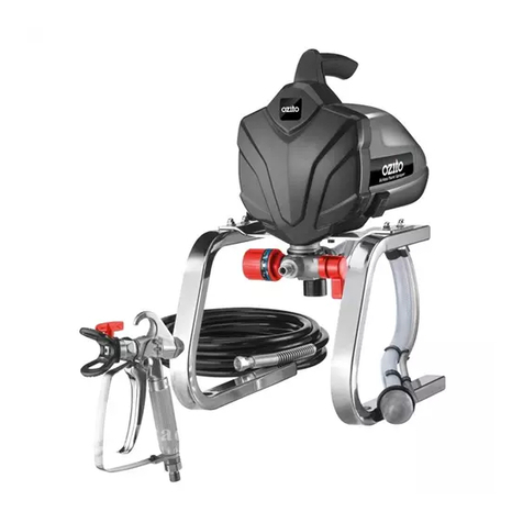
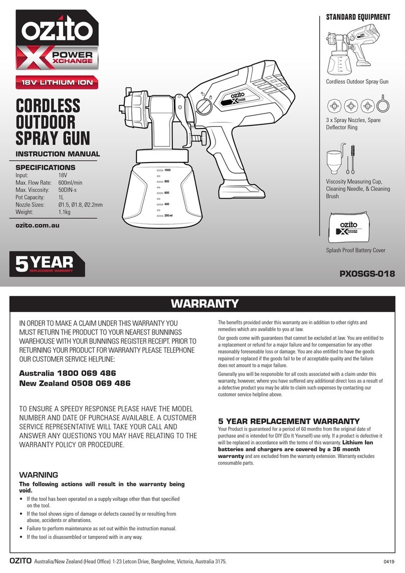
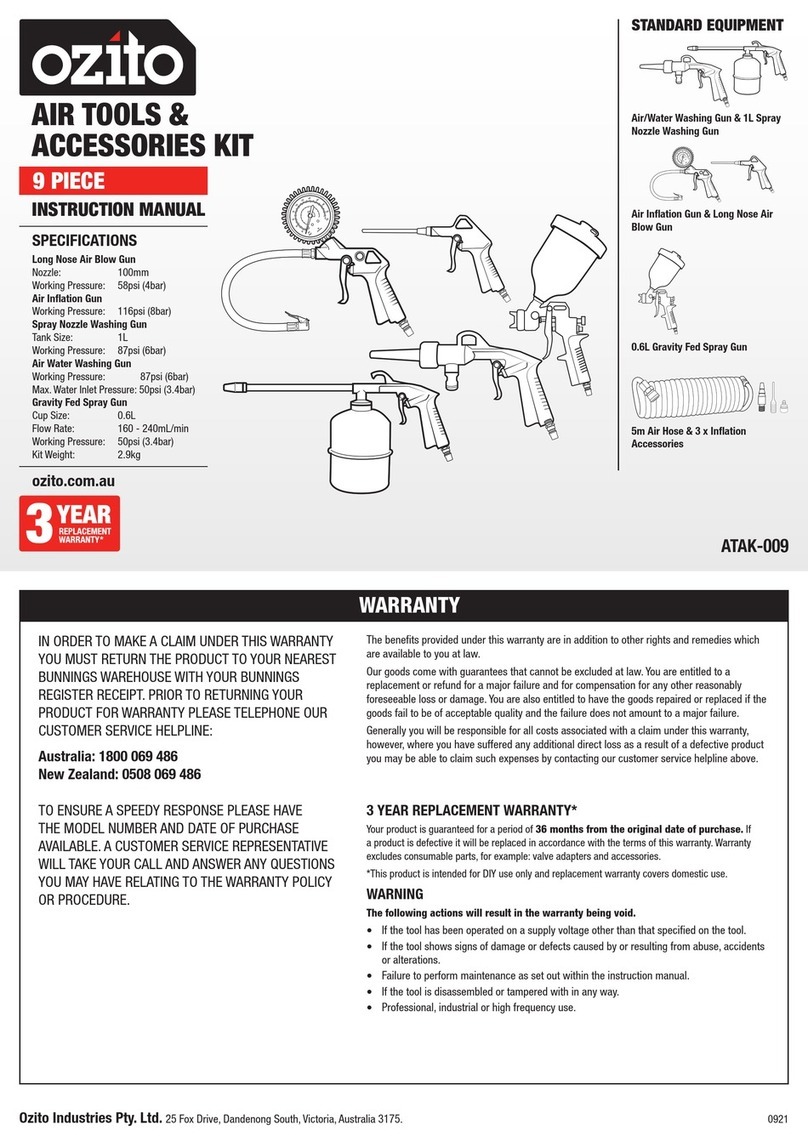
Ozito ASG-7000 User manual

1
AIRLESS PAINT
SPRAYER
700W
INSTRUCTION MANUAL
SPECIFICATIONS
Input Power: 700W
Voltage: 220-240V ~50Hz
Max. Pressure: 3,000psi (21MPa)
Max. Flow Rate: 1.0L/min
Spray Tip Size: 517 (Supplied)
Suitable Spray Tips: 0.013 - 0.021”
Max. Viscosity: 100DIN-s
Outlet Paint Connector: G¼”-19”
Max. Hose Pressure: 3,300psi (22.8MPa)
High Pressure Hose: 7.5m
Paint Temperature: 5-40°C
Weight: 10.5kg
ASG-7000
STANDARD EQUIPMENT
IN ORDER TO MAKE A CLAIM UNDER THIS
WARRANTY YOU MUST RETURN THE PRODUCT
TO YOUR NEAREST BUNNINGS WAREHOUSE WITH
YOUR BUNNINGS REGISTER RECEIPT. PRIOR TO
RETURNING YOUR PRODUCT FOR WARRANTY
PLEASE TELEPHONE OUR CUSTOMER SERVICE
HELPLINE:
Australia 1800 069 486
New Zealand 0508 069 486
1 YEAR REPLACEMENT WARRANTY
Your product is guaranteed for a period of 12 months from the
original date of purchase and is intended for DIY (Do It Yourself)
use only. If a product is defective it will be replaced in accordance
with the terms of this warranty. Warranty excludes consumable
parts, for example: valve adapters and accessories.
WARNING
The following actions will result in the warranty being void.
• If the tool has been operated on a supply voltage other
than that specified on the tool.
• If the tool shows signs of damage or defects caused
by or resulting from abuse, accidents or alterations.
• Failure to perform maintenance as set out within the
instruction manual.
• If the tool is disassembled or tampered with in any way.
• Professional, industrial or high frequency use.
WARRANTY
TO ENSURE A SPEEDY RESPONSE PLEASE
HAVE THE MODEL NUMBER AND DATE OF
PURCHASE AVAILABLE. A CUSTOMER SERVICE
REPRESENTATIVE WILL TAKE YOUR CALL
AND ANSWER ANY QUESTIONS YOU MAY
HAVE RELATING TO THE WARRANTY POLICY
OR PROCEDURE.
OZITO Australia/New Zealand (Head Office) 1-23 Letcon Drive, Bangholme, Victoria, Australia 3175.
The benefits provided under this warranty are in addition
to other rights and remedies which are available to you at law.
Our goods come with guarantees that cannot be excluded
at law. You are entitled to a replacement or refund for a major
failure and for compensation for any other reasonably foreseeable
loss or damage. You are also entitled to have the goods repaired
or replaced if the goods fail to be of acceptable quality and the
failure does not amount to a major failure.
Generally you will be responsible for all costs associated with
a claim under this warranty, however, where you have suffered
any additional direct loss as a result of a defective product you
may be able to claim such expenses by contacting our customer
service helpline above.
ozito.com.au
Airless Sprayer
17
19
17
19
24
27
Spray Gun & High Pressure Hose
17
19
17
19
24
27
3 x Spanners, Spare Spray Gun
Filter, Fine Needle & Cleaning
Brush
17
19
17
19
24
27
4 x Bolts, 4 x Washers, 4 x Spring
Washers & Hex Key
0720

ONLINE MANUAL
Scan this QR Code with
your mobile device to take
you to the online manual.
Frame Connection
1. Insert the paint station into the frame,
aligning the 4 bolt holes (2 either side).
2. Place a spring washer and then a
washer onto each bolt. Insert the bolt
assemblies into the bolt holes and
tighten using the supplied hex key.
Hose Connection
Note: The air caps on the paint station and air hose will need to be
removed prior to connection.
1. Connect the high pressure hose to the
paint outlet and tighten clockwise.
2. Connect the other end of hose to the
gun inlet and tighten clockwise.
3. Ensure all connections have been
correctly tightened with a 19mm
spanner on the hose, and a 17mm
spanner to hold the connection.
4. Connect the inlet hose and return pipe
to the paint station.
5. Secure the inlet hose by
tightening the screw on the hose
clamp.
1. Carry Handle
2. Paint Outlet Port
3. Power Cord
4. Priming Lever
5. Return Pipe Port
6. Frame
7. Return Pipe
8. Inlet Filter
9. Inlet Hose
10.Sprayer Unit
11.Inlet Hose Port
12.Pressure Control Dial
13.On/O Switch
14.Handle
15.Spray Gun Inlet
16.Spray Gun Trigger
17.Handle Guard
18.Tip Guard
19.Spray Tip
20.Trigger Locking Lever
AIRLESS SPRAY GUN
KNOW YOUR PRODUCT
1. ASSEMBLY
SETUP & PREPARATION
1
14 15
2
11
3
4
5
6
18
17
16
13
19
10
12
20
789
WARNING! ENSURE THE TOOL IS TURNED OFF
AND DISCONNECTED FROM THE POWER SUPPLY
BEFORE PERFORMING ANY OF THE FOLLOWING
OPERATIONS.

Locking The Spray Gun Trigger
The spray gun trigger should be locked prior to priming the spray
station to prevent accidentally activating the spray gun.
1. To lock the spray gun trigger, rotate the
trigger locking lever clockwise until it
points rearwards.
2. To unlock the trigger, rotate the trigger
locking lever anti-clockwise.
Paint Preparation
You do not need to thin paint for use
in this spray gun. The inlet hose and
return pipe can be placed directly
into the paint tin for spraying.
For best results we recommend
straining the paint prior to use.
This will improve the nal result by
eliminating any contaminants and
lumps present in the paint.
WARNING! PAINTING CAN BE MESSY, AND SPRAY
MATERIALS MAY BE EMITTED AT HIGH PRESSURE
FROM THE SPRAY GUN. WEAR APPROPRIATE
SAFETY GEAR AND ENSURE SURFACES YOU DO
NOT WANT TO GET PAINT/SPRAY MATERIAL ON
ARE ADEQUATELY COVERED AND PROTECTED.
Spray Tip & Guard
Note: The spray gun comes assembled from the factory. If the spray
gun has been disassembled for cleaning or priming, follow the steps
below to re-assemble.
1. Push the mesh lter into the
spray head and then insert
the handle over the mesh
lter.
2. Ensure the trigger guard is
attached to the handle and
tighten the handle using a
19mm spanner.
3. Screw the tip guard loosely
onto the spray gun and insert
the spray tip into the tip guard.
4. Fully tighten the tip guard onto
the spray gun with the 27mm
spanner.
2. PREPARING THE MACHINE
WARNING! ENSURE THE TOOL IS TURNED OFF
AND DISCONNECTED FROM THE POWER SUPPLY
BEFORE PERFORMING ANY OF THE FOLLOWING
OPERATIONS.
WARNING! THE TOOL IS RECOMMENDED FOR
USE WITH A RESIDUAL CURRENT DEVICE WITH A
RATED CURRENT OF 30mA OR LESS.

Priming The Pump
The airless sprayer needs to be primed every time a spray material is
used. Whether you are setting the machine up for use after cleaning/
storage, changing paint colours, or swapping from a stain to varnish,
you will need to follow the priming procedure for the pump and spray
gun.
Note: When changing between dierent paint colours, it is
recommended to clean the sprayer to prevent paint mixing and for
best results.
1. Fully submerge the inlet lter in the spray
material.
2. To prevent any lubricants or impurities
getting into your spray material, hold
the return pipe over a waste bucket and
continue with the priming steps.
When spray material starts coming out of
the return pipe, submerge the return pipe
in the spray material tin/bucket with the
inlet hose.
2. Set the priming lever to the prime position.
3. Adjust the pressure dial to the maximum
position by rotating it clockwise.
4. Switch on the unit and let the paint cycle
through the system for a few minutes.
5. Wait for any air bubbles to
clear the return pipe (this is
indicated by a steady stream
of paint out of return pipe)
then switch o the unit.
Priming The Spray Gun & High Pressure Hose
1. Remove the tip guard and spray
tip from the spray gun.
2. Set the priming lever to the spray
position.
3. Point the spray gun nozzle into a waste
bucket, then press and hold the trigger to
relieve the pressure in the line.
4. While still holding down the trigger, switch
on the unit.
5. Keep holding down the trigger until spray material is emitted from
the spray gun, at which point direct the spray gun back into the
spray material tin for a few seconds. Release the spray gun trigger.
8. Switchotheunit.
9. Re-assemble the spray tip
and tip guard. The sprayer is
now ready to use.
Note: The motor automatically shuts o once the operating pressure
is reached and will start-up again when it drops below the cut-in
pressure. This is part of normal operation and does not indicate a
fault with the machine.
PRESSURE
CONTROL
PRIME
SPRAY
WASTE

Adjusting The Spray Pressure
The spray pressure setting required will vary depending on many
factors such as the viscosity of the material, the temperature, the
wear on the spray tip, size of the nozzle, distance to the work surface,
length of the hose, etc. It will therefore need to be adjusted until an
even spray pattern is achieved before starting to paint.
1. Set the pressure control dial to
approximately medium pressure.
2. Test this pressure setting on a
scrap piece of material.
Too little pressure will result
in streaks with more paint
appearing in the spray
pattern.
Too much pressure will result
in overspray, material wastage
and premature wear on the
airless sprayer parts.
Note: As best practice, it is recommended to start at a lower pressure
and then adjust it up until the streaks start to disappear and an even
spray output is achieved.
3. Continue adjusting the pressure
setting and testing it until a smooth
even consistency is achieved.
Note: Take note of how far the sprayer is
held from the test surface whilst testing,
as this will aect obtaining an even
spray output. You will want to maintain
this distance when spraying the work surface.
Note: If the streaks are still present even at maximum pressure, a
narrower spray tip may be required.
Adjusting Spray Speed
The selected spray pressure will
aect the speed at which you’ll
need to move the spray gun. Lower
pressures will require slower speeds
and higher pressures, faster speeds.
1. On a scrap piece of material,
practice applying steady strokes
at the speed required to achieve an even spray pattern.
Pressure Release Procedure
WARNING! PERFORM THE FOLLOWING
PROCEDURE FOR PRESSURE RELEASE WHEN
SHUTTING DOWN THE AIRLESS SPRAYER FOR ANY
PURPOSE, INCLUDING CLEANING OR ADJUSTING.
1. With the machine switched on, rotate the
priming lever into the prime position.
2. Switch o the spray system.
3. Aim the spray gun into the paint bucket
and squeeze the trigger to release any
remaining pressure in the gun. Keep
holding the trigger until the spray material
comes out.
4. Lock the spray gun trigger.
Changing The Spray Direction
1. Perform the Pressure Release Procedure described above.
WARNING! ENSURE THE TOOL IS SWITCHED OFF
& THE CORD IS UNPLUGGED WHEN PERFORMING
THE OPERATION BELOW.
2. Rotate the tip guard to match the
direction of preferred spray pattern.
3. Flip the priming lever back into the spray
position and switch the unit on. The
sprayer is now ready for use again.
ASG-7000
3. CONTROLS
OPERATION
SPRAY
PRESSURE
CONTROL
PRESSURE
CONTROL
PRIME
HIGH
PRESSURE
FAST
LOW
PRESSURE
SLOW
WARNING! WEAR APPROPRIATE SAFETY
GEAR INCLUDING EYE, EAR AND BREATHING
PROTECTION BEFORE COMMENCING USE.
HORIZONTAL VERTICAL

Spraying Technique
The spraying result depends considerably on how well prepared the
surface is for painting. Carefully complete proper surface preparation
according to the paint manufacturer’s instructions.
1. Turn the airless sprayer on. Ensure
the priming lever is in the spray
position. Release the trigger lock.
2. Keep the spray gun perpendicular to the surface.
3. Move the gun with the entire arm, not by exing the wrist. This
will keep the spray gun at right angles to the surface, keeping the
pattern even.
4. Start the stroke before the edge of the area being sprayed. Begin
the movement and then squeeze the trigger.
5. Move the spray gun along the surface at a steady pace and then
release the trigger once past the opposite edge of the area being
sprayed.
6. Overlap each stroke to
ensure even coverage.
4. USING THE SPRAYER
SPRAY
Helpful Hints
1. Do not spray outdoors on a windy day as the results may be
unsatisfactory.
2. Only apply one coat at a time, always allow a coat to completely
dry before adding another coat.
3. Avoid stopping and starting as this can lead to a patchy nish.
It is best to start spraying outside the surface to be sprayed and
avoid stopping in the middle of the surface, continue just past the
opposite edge.
4. If no spray comes out of the spray gun, the tip may have dried and
clogged. Switch o the unit, lock the spray gun trigger and rotate
the spray tip by 180°. Switch on the unit, unlock the trigger then
squeeze and hold the trigger to spray material through the gun.
Repeat this 2-3 times.
If the procedure above does not x the issue, Switch o the
unit and follow the cleaning procedure for the spray tip in the
‘CLEANING THE SPRAY GUN’ section of the Cleaning &
Maintenance Manual.
Interim Procedure
If you are taking a break for more than several minutes, follow the
procedure below to prevent paint from drying and forming a blockage
in the spray gun.
1. Perform the Pressure Release Procedure described in the
‘CONTROLS’ section.
2. Remove the spray tip from the spray gun and submerge it in a
container of the appropriate solvent (water if water based spray
material was used, or a suitable cleaning solution if oil based).
3. When you are ready to start spraying again, wipe the spray tip dry,
re-assemble the spray gun, prime the machine again and resume
use as normal
WARNING! IF YOU ARE TAKING A BREAK, YOU WILL
NEED TO PERFORM THE CLEANING PROCEDURE
ON THE UNIT. DO NOT LEAVE SPRAY MATERIAL
SITTING IN THE UNIT AS THIS CAN DRY AND
CLOG THE PARTS, RENDERING THE SPRAYER
INOPERABLE.
Clean After Each Use
Follow the cleaning procedure in the separate cleaning manual
IMMEDIATELY AFTER each use. Ensure the unit is thoroughly
cleaned before storing to prevent build up of dried paint which can
cause blockages and stop the unit from working.
WARNING! NOT FOLLOWING THE CLEANING STEPS
WILL RESULT IN THE MACHINE CLOGGING AND
BREAKAGE. MALFUNCTIONS CAUSED BY FAILURE
TO FOLLOW CLEANING PROCEDURES ARE NOT
COVERED BY THE PRODUCT WARRANTY.
WARNING! ENSURE THAT THE AIRLESS SPRAYER
HAS BEEN PROPERLY PRIMED BEFORE
COMMENCING SPRAYING PROCEDURE.

5. TROUBLESHOOTING
DESCRIPTION OF SYMBOLS
Wear eye, ear & breathing
protection Megapascals
Warning
Regulatory Compliance Mark
(RCM)
VVolts Hz
W
Hertz
~
psi
MPa
L/min
Alternating Current Watts
Pound per square inchLitres per minute
Read Instruction Manual
SPARE PARTS
Spare parts can be ordered from the Special Orders Desk
at your local Bunnings Warehouse.
For further information, or any parts not listed here, visit
www.ozito.com.au or contact Ozito Customer Service:
Australia 1800 069 486
New Zealand 0508 069 486
E-mail: [email protected]
Symptom Possible Cause Suggested Solution
Little or no
material ow
Nozzle clogged
Follow instructions in
the Cleaning Manual for
cleaning the spray tip
Suction tube clogged Clean
Pressure control dial
turned too low
Increase pressure
control dial setting
Suction tube loose Insert & tighten the
hose clamp
Inlet lter clogged Clean or replace
Material
leaking
Nozzle loose Tighten
Nozzle worn Replace
Nozzle seal worn Replace
Material build-up on air
cap & nozzle Clean
Atomisation is
too coarse
Larger tip & lter
required
Refer to spray tip
selection chart
Material volume too large Decrease pressure
control dial setting
Nozzle clogged Clean
Inlet lter clogged Clean or replace
Pattern runs or
sags
Applying too much
material
Adjust pressure
control dial or increase
movement speed of
spray gun
Too much
overspray
Gun too far from spray
object Reduce distance
Too much material
applied
Decrease pressure
control dial setting
Pattern is very
light & splotchy
Moving the spray gun
too fast
Adjust pressure control
dial or decrease
movement speed of
spray gun
Spluttering
paint
Air bubbles in the return
pipe
Follow priming
instructions to remove
air bubbles
Inlet hose not
sucking up
water when
cleaning the
unit
Lack of pressure
Follow priming
instructions to re-prime
the unit
Machine not
priming
Spray gun tip is clogged Clean spray gun tip
Spray gun lter is
clogged Clean spray gun lter
Priming lever is not set
to prime
Set priming lever to
prime
Paint outlet & inlet are
clogged Clean paint outlet & inlet
Pressure too low Set pressure control dial
higher
Inlet lter is clogged Clean inlet lter
Paint station
is starting
& stopping
automatically
This is normal; this
ensures the correct
operating pressure is
maintained
No issue
Power tools that are no longer usable should not be
disposed of with household waste but in an environmentally
friendly way. Please recycle where facilities exist. Check
with your local council authority for recycling advice.
Recycling packaging reduces the need for landll and raw
materials. Reuse of recycled material decreases pollution in
the environment. Please recycle packaging where facilities
exist. Check with your local council authority for recycling
advice.
CARING FOR THE ENVIRONMENT

1
WARNING! When using mains-powered tools, basic safety precautions, including the
following, should always be followed to reduce risk of re, electric shock, personal injury and
material damage.
Read the whole manual carefully and make sure you know how to switch the tool o in an emergency,
before operating the tool.
Save these instructions and other documents supplied with this tool for future reference.
The charger has been designed for 230V and 240V only. Always check that the power supply corresponds
to the voltage on the rating plate.
Note: The supply of 230V and 240V on Ozito tools are interchangeable for Australia and New Zealand.
If the supply cord is damaged, it must be replaced by an electrician or a power tool repairer in order to
avoid a hazard.
Using an Extension Lead
Always use an approved extension lead suitable for the power input of this tool. Before use, inspect the
extension lead for signs of damage, wear and ageing. Replace the extension lead if damaged or defective.
When using an extension lead on a reel, always unwind the lead completely. Use of an extension lead
not suitable for the power input of the tool or which is damaged or defective may result in a risk of re and
electric shock.
The power supply for this products charger should be protected by a residual current device (rated at
30mA or less). A residual current device reduces the risk of electric shock.
WARNING! The appliance is not to be used by persons (including children) with
reduced physical, sensory or mental capabilities, or lack of experience and knowledge,
unless they have been given supervision or instruction.
Young children should be supervised to ensure that they do not play with the appliance.
Before connecting a tool to a power source (mains switch power point receptacle, outlet, etc.) be sure
that the voltage supply is the same as that specied on the nameplate of the tool. A power source with a
voltage greater than that specied for the tool can result in serious injury to the user, as well as damage to
the tool. If in doubt, do not plug in the tool. Using a power source with a voltage less than the nameplate
rating is harmful to the motor.
The ASG-7000 Airless Spray Gun operates at very high pressure. For safe operation the following must be
observed at all times.
• Do not point the spray gun at yourself or any other person. Injury from penetration to the skin and paint
solvents being injected into the body can result.
• Always check for leaks and correct operation before use. Never operate the spray gun if there are any
leaks or faults. Faults or leaks can cause injury.
• Release the pressure when not in use. Pressure can remain in the unit and hose when switched o.
• Always remove the plug from the mains socket before making any adjustments or performing
maintenance.
• Recommendations for the use of a residual current device with a rated residual current of 30mA or
less.
• NEVER under any circumstances aim the nozzle at another person or animal. In the event of an injury
occurring, seek medical advice immediately.
• The spray gun must not be used for spraying ammable paints and solvents with a ash point of less
than 21ºC.
• Always ensure there is adequate ventilation when spraying.
• The use of ear protection is recommended.
• Eye protection is recommended to keep hazardous vapours and liquids out of eyes.
• Always wear a face mask when spraying.
• Always read the paint manufacturers thinning instructions before using.
• Always keep the spray basket nozzle in place during use. Never allow the spray to come in direct
contact with the skin.
• Never immerse the spray gun in liquid. This could lead to electric shock, personal injury and material
damage.
• The spray gun must not be cleaned by using ammable liquids with a ash point of less than 21ºC.
• NEVER spray near a naked ame, including an appliance pilot light.
• NEVER smoke whilst spraying.
• NEVER allow children to operate or play with the spray gun.
• Before cleaning, always disconnect the appliance from the mains supply.
• After every use ensure you clean your spray gun thoroughly.
• NEVER use the spray gun outside when it is raining.
• Injury where paint or solvent injection into the skin or body occurs can be very serious. Always seek
professional medical help and advise the paints or solvents used.
• NEVER use the spray gun without the trigger safety guard tted.
• NEVER put your hand in front of the gun. Gloves will not provide protection against an injection injury.
• ALWAYS lock the gun trigger, shut the uid pump o and release all pressure before servicing,
cleaning the tip guard, changing tips, or leaving unattended. Pressure will not be released by turning
o the machine. The PRIME/SPRAY valve or pressure bleed valve must be turned to their appropriate
positions to relieve system pressure.
• NEVER use a spray gun without a working trigger lock and trigger guard in place.
• All accessories must be rated at or above the maximum operating pressure range of the sprayer. This
includes spray tips, guns, extensions, and hose.
• High-pressure hoses must be checked thoroughly before they are used. Replace any damaged high-
pressure hose immediately.
• Never pull on the high-pressure hose to move the device.
• Do not twist the high-pressure hose.
• Do not put the high-pressure hose into solvents. Use only a wet cloth to wipe down the outside of the
hose.
• Lay the high-pressure hose in such a way as to ensure that it cannot be tripped over.
• Follow material and solvent manufacturer’s warnings and instructions. Be familiar with the coating
material’s SDS sheet and technical information to ensure safe use.
• Use lowest possible pressure to ush equipment.
• Protective clothing, gloves and possibly skin protection cream are necessary for the protection of the
skin. Observe the regulations of the manufacturer concerning coating materials, solvents and cleaning
agents in preparation, processing and cleaning units.
• ALWAYS follow the material manufacturer’s instructions for safe handling of paint and solvents.
• Do not spray on windy days.
• Never leave this equipment unattended. Keep away from children or anyone not familiar with the
operation of airless equipment.
AIRLESS SPRAYER SAFETY WARNINGS
GENERAL POWER TOOL SAFETY WARNINGS
ELECTRICAL SAFETY
WARNING! Read all safety warnings and all instructions. Failure to follow the
warnings and instructions may result in electric shock, re and/or serious injury.
Save all warnings and instructions for future reference. The term “power tool” in the warnings
refers to your mains-operated (corded) power tool or battery-operated (cordless) power tool.
1. Work area safety
a. Keep work area clean and well lit. Cluttered or dark areas invite accidents.
b.Donotoperatepowertoolsinexplosiveatmospheres,suchasinthepresenceofammable
liquids, gases or dust. Power tools create sparks which may ignite the dust or fumes.
c. Keep children and bystanders away while operating a power tool. Distractions can cause you to
lose control.
2. Electrical safety
a. Power tool plugs must match the outlet. Never modify the plug in any way. Do not use any
adapter plugs with earthed (grounded) power tools. Unmodied plugs and matching outlets will
reduce risk of electric shock.
b. Avoid body contact with earthed or grounded surfaces, such as pipes, radiators, ranges and
refrigerators. There is an increased risk of electric shock if your body is earthed or grounded.
c. Do not expose power tools to rain or wet conditions. Water entering a power tool will increase the
risk of electric shock.
d. Do not abuse the cord. Never use the cord for carrying, pulling or unplugging the power tool.
Keep cord away from heat, oil, sharp edges or moving parts. Damaged or entangled cords increase
the risk of electric shock.
e. When operating a power tool outdoors, use an extension cord suitable for outdoor use. Use of a
cord suitable for outdoor use reduces the risk of electric shock.
3. Personal safety
a. Stay alert, watch what you are doing and use common sense when operating a power tool. Do
notuseapowertoolwhileyouaretiredorundertheinuenceofdrugs,alcoholormedication. A
moment of inattention while operating power tools may result in serious personal injury.
b.Use personal protective equipment. Always wear eye protection. Protective equipment such as dust
mask, non-skid safety shoes, hard hat, or hearing protection used for appropriate conditions will reduce
personal injuries.
c.Preventunintentionalstarting.Ensuretheswitchisintheo-positionbeforeconnectingto
power source and/or battery pack, picking up or carrying the tool. Carrying power tools with your
nger on the switch or energising power tools that have the switch on invites accidents.
d. Remove any adjusting key or wrench before turning the power tool on. A wrench or a key left
attached to a rotating part of the power tool may result in personal injury.
e. Do not overreach. Keep proper footing and balance at all times. This enables better control of the
power tool in unexpected situations.
f. Dress properly. Do not wear loose clothing or jewellery. Keep your hair, clothing and gloves away
from moving parts. Loose clothes, jewellery or long hair can be caught in moving parts.
g. If devices are provided for the connection of dust extraction and collection facilities, ensure
these are connected and properly used. Use of dust collection can reduce dust-related hazards.
h. Do not let familiarity gained from frequent use of tools allow you to become complacent and
ignore tool safety principles. A careless action can cause severe injury within a fraction of a second.
4. Power tool use and care
a. Do not force the power tool. Use the correct power tool for your application. The correct power
tool will do the job better and safer at the rate for which it was designed.
b.Donotusethepowertooliftheswitchdoesnotturnitonando.Any power tool that cannot be
controlled with the switch is dangerous and must be repaired.
c. Disconnect the plug from the power source and/or the battery pack from the power tool before
making any adjustments, changing accessories, or storing power tools. Such preventive safety
measures reduce the risk of starting the power tool accidentally.
d. Store idle power tools out of the reach of children and do not allow persons unfamiliar with the
power tool or these instructions to operate the power tool. Power tools are dangerous in the hands
of untrained users.
e. Maintain power tools. Check for misalignment or binding of moving parts, breakage of parts and any
other condition that may aect the power tool’s operation. If damaged, have the power tool repaired
before use. Many accidents are caused by poorly maintained power tools.
f. Keep cutting tools sharp and clean. Properly maintained cutting tools with sharp cutting edges are
less likely to bind and are easier to control.
g. Use the power tool, accessories and tool bits etc. in accordance with these instructions, taking
into account the working conditions and the work to be performed. Use of the power tool for
operations dierent from those intended could result in a hazardous situation.
h. Keep handles and grasping surfaces dry, clean and free from oil and grease. Slippery handles and
grasping surfaces do not allow for safe handling and control of the tool in unexpected situations.
5. Service
a.Haveyourpowertoolservicedbyaqualiedrepairpersonusingonlyidenticalreplacement
parts. This will ensure that the safety of the power tool is maintained.
1219
ASG-7000
AIRLESS
PAINT SPRAYER
700W
CLEANING &
MAINTENANCE MANUAL
WARNING! THE CLEANING PROCESS MUST BE FOLLOWED IMMEDIATELY
AFTER USE TO PREVENT PAINT FROM DRYING INSIDE THE PUMP AND HOSE.
FAILURE TO FOLLOW THIS INSTRUCTION MAY PERMANENTLY SEIZE THE
PAINT SPRAYER.

1. Tensioning Knob
2. Upper Blade Pulley
3. Upper Door
4. ON/OFF Switch
5. Lower Door
6. Rip Fence
7. Rip Fence Locking Lever
8. Lower Blade Pulley
9. Upper Door Lock
10. Blade Guard Adjustment
11. Blade Guard
12. Upper Blade Guide
13. Saw Table
14. Stabiliser Bar
15. Lower Door Lock
16. Machine Base
2
1. Handle
2. Spray Gun Inlet
3. Spray Gun Trigger
4. Handle Guard
5. Tip Guard
6. Spray Tip
7. Trigger Locking Lever
CONTENTS
KNOW YOUR PRODUCT
KNOW YOUR PRODUCT......................................................................................................Page 2
CLEANING
1. Pressure Release Procedure .............................................................................................. Page 4
2. Solvent Types ......................................................................................................................Page 5
3. Rinsing The Inlet Filter ........................................................................................................ Page 6
4. Cleaning The Pump ............................................................................................................ Page 7
5. Cleaning The Spray Gun .....................................................................................................Page 9
MAINTENANCE
6. Worn Spray Tips ..................................................................................................................Page 11
7. Spray Tip Selection ............................................................................................................. Page 12
8. Storage ................................................................................................................................Page 13
SPARE PARTS...................................................................................................................... Page 15
SPRAY GUN
1 2
54
3
6
7

ONLINE MANUAL
Scan this QR Code with
your mobile device to take
you to the online manual.
3
KNOW YOUR PRODUCT
8. Carry Handle
9. Paint Outlet Port
10. Power Cord
11. Priming Lever
12. Return Pipe Port
13. Frame
14. Return Pipe
15. Inlet Filter
16. Inlet Hose
17. Sprayer Unit
18. Inlet Hose Port
19. Pressure Control Dial
20. On/O Switch
AIRLESS PAINT SPRAYER
8 9
18
10
11
12
13
14
20
17
19
1516

4
1. With the machine switched on, rotate the priming lever into
the prime position.
2. Switch o the spray system.
3. Aim the spray gun into the paint bucket and squeeze
the trigger to release any remaining pressure in the
gun. Keep holding the trigger until the spray material
comes out in a small, steady stream.
4. Lock the spray gun trigger.
CLEANING
1. PRESSURE RELEASE PROCEDURE
WARNING! BEFORE BEGINNING THE CLEANING PROCESS, ENSURE
THAT THE PRESSURE RELEASE PROCEDURE BELOW IS PERFORMED.
WARNING! ALWAYS WEAR EYE, EAR AND APPROPRIATE BREATHING
PROTECTION WHEN CLEANING THE AIRLESS PAINT SPRAYER.
PRIME
WARNING! SPRAY MATERIALS MAY BE EMITTED AT HIGH PRESSURE
FROM THE SPRAY GUN. WEAR APPROPRIATE SAFETY GEAR AND
ENSURE SURFACES YOU DO NOT WANT TO GET PAINT/SPRAY
MATERIAL ON ARE ADEQUATELY COVERED AND PROTECTED.

5
Water Versus Oil Based
If the coating material was water based, use ONLY water when performing the cleaning
procedure. Use of solvents meant for oil based materials on water based paints will cause the
paint residue to harden and block the paint system. This will be extremely dicult to clean.
If coating material was oil based, use ONLY the appropriate cleaning solution. Read the
cleaning instructions printed on the coating material’s label to determine which solvent you
need. The following solvents for oil based coating materials are safe to use in the airless paint
sprayer:
• Mineral Turpentine
• Paint Thinner
For Water Based Cleaning
We recommend the use of 30-40 litres when performing the cleaning procedure.
For Oil Based Cleaning
We recommend 1-2 litres of the appropriate solvent based cleaner when performing the
cleaning procedure.
Note: Mineral Turpentine SHOULD NOT be mixed with water at any stage during the cleaning
process.
2. SOLVENT TYPES
WARNING! ALWAYS READ AND FOLLOW THE MANUFACTURER’S
INSTRUCTIONS FOR HANDLING AND USE OF THE SOLVENTS. SOME
SOLVENTS MAY BE TOXIC AND APPROPRIATE SAFETY MEASURES
MUST BE STRICTLY FOLLOWED TO AVOID SAFETY HAZARDS.

6
3. RINSING THE INLET FILTER
WARNING! BEFORE CLEANING THE MACHINE, ENSURE THE PRESSURE
CONTROL DIAL IS SET TO THE MEDIUM SETTING & THE PRIMING LEVER
IS SET TO THE ‘PRIME’ POSITION.
1. Lift the inlet hose and return pipe out of the spray material and allow any excess to drip
back into the tin/bucket.
2. Unscrew the buttery clamp on the inlet hose.
3. Remove the lter and clamp and rinse them out with
the appropriate cleaning solution.
Note: If the lter cannot be cleaned it must be replaced.
4. Wipe o any excess spray material from the outside of the inlet hose and return pipe with a
dry rag.
5. Re-attach the clamp and lter to the inlet hose and secure in place.
WARNING! ENSURE THE TOOL IS SWITCHED OFF & DISCONNECTED
FROM THE POWER SUPPLY BEFORE PERFORMING ANY OF THE
FOLLOWING OPERATIONS.

7
1. Prepare 2 buckets, 1 for rinsing and 1 for waste.
2. Pour a little of the appropriate solvent (water, paint thinner,
mineral turpentine) into the waste bucket and place the
inlet hose & return pipe in. Allow as much spray material
stuck in the hoses to drip out as possible.
3. Fill the rinsing bucket with some of the solvent and
submerge the rinsed inlet hose in it.
Note: Top up the rinsing bucket with more solvent if the inlet
lter stops being submerged. Do not allow the rinsing bucket
to run dry with the pump still running at any point in the
procedure below.
4. Ensure the priming lever is in the ‘prime’ position then
switch the unit on. Check the waste bucket and wait for a
constant stream of clear solvent to come out of the return
pipe.
Note: The solvent in the rinsing bucket may turn cloudy from excess spray material in the
hose. Wait for the solvent coming out of the return pipe to turn the same colour, then switch o
the unit, pour the contents of the rinsing bucket into the waste bucket and repeat steps 3 & 4
until the solvent coming out of the return pipe runs clear.
4. CLEANING THE PUMP
WARNING! THIS CLEANING PROCESS MUST BE FOLLOWED
IMMEDIATELY AFTER USE TO PREVENT PAINT FROM DRYING INSIDE
THE PUMP & HOSE. FAILURE TO FOLLOW THIS INSTRUCTION MAY
PERMANENTLY SEIZE THE PAINT SPRAYER.
RINSE WASTE
WASTE
RINSE WASTE
PRIME

8
5. Ensure the pressure control dial is set to
medium and ip the priming lever to the
spray position.
6. Aim the spray gun at the waste bucket, then squeeze and
hold the trigger until most of the paint is removed from the
high pressure hose.
Note: Submerging the tip into the solvent before spraying will
help to reduce back spray and splatters.
Note: If no spray comes out of the spray gun, the tip may
have dried and clogged. Switch o the unit and follow the
cleaning procedure for the spray tip in the ‘CLEANING THE
SPRAY GUN’ section of this manual.
7. Lock the spray gun trigger and rotate the spray tip by 180°.
8. Unlock the trigger. Squeeze and hold the trigger to spray solvent
through the gun & high pressure hose.
9. Repeat step 8 until only solvent is emitted from the spray gun.
Continue topping up the rinsing bucket with solvent as required.
10. Perform the Pressure Release Procedure.
11. Disconnect the inlet hose & return pipe from the sprayer,
shake out any excess solvent and allow to dry.
SPRAY
PRESSURE
CONTROL
WASTE
WASTE
a.
b.

9
The procedures described below will need to be repeated even if already completed whilst
cleaning the pump from the previous section.
1. Disconnect the high pressure hose from the sprayer
unit and the spray gun from the high pressure hose by
loosening the nut with a 19mm spanner.
2. Place one end of the high pressure hose over the
waste bucket. Keep the other end of the hose higher
up and begin coiling the hose. This will allow any
remaining solvent in the hose to drip out.
3. Remove the tip guard and spray tip from
the spray gun with the 27mm spanner.
Rinse these in the solvent to remove any
remaining spray material.
Note: There is a small spacer and washer used to locate
the spray tip within the tip guard. Be careful not to lose
these components when removing the tip guard from the
spray gun.
5. CLEANING THE SPRAY GUN
WARNING! ENSURE THE TOOL IS SWITCHED OFF & DISCONNECTED
FROM THE POWER SUPPLY BEFORE PERFORMING ANY OF THE
FOLLOWING OPERATIONS.
WARNING! ENSURE THAT THE PRESSURE RELEASE PROCEDURE HAS
BEEN PERFORMED BEFORE COMMENCING THESE STEPS.

10
4. Unscrew the nut below the handle using a 19mm spanner
and a shifter (not supplied).
Note: Using a shifter or bench vice to hold the upper part of
the spray gun will make this step much easier.
5. Unscrew the handle and remove the
mesh lter. Clean all components in the
solvent.
6. To clean the mesh lter, remove the cap at the end of the lter and pull the mesh section o.
Use the supplied brush to scrub the inside of the mesh lter.
Note: After cleaning, inspect the condition of the lter. If the mesh lter is clogged with dried
paint, has started fraying, or has deformed out of shape, it will need to be replaced.
7. Wipe down all parts of the spray gun and allow to dry before re-assembling.

11
When a spray tip starts to wear, the orice gets bigger and rounder reducing the fan pattern
size. This can result in less control and more overspray during use.
Some signs to look out for include:
• Painting takes longer than usual,
• More paint is consumed than usual,
• The nish is uneven and more runs appear than is usual.
If this issue occurs, do not try to compensate by increasing the spray pressure; this will
just waste spray material and increase wear on the pump. Replace the worn tip. Correctly
replacing the worn spray tip when necessary can improve the working life of the sprayer.
To help extend the life of spray tips,
• Spray at the lowest pressure that provides an even spray pattern;
• Filter the spray material with a stainer (not supplied) before use;
• Clean the lters after every use;
• Clean the spray tip with the soft-bristled brush.
6. WORN SPRAY TIPS
WARNING! BEFORE CARRYING OUT ANY MAINTENANCE PROCEDURE,
MAKE SURE THAT THE TOOL IS DISCONNECTED FROM THE POWER
SUPPLY TO PREVENT ACCIDENTAL STARTING.
MAINTENANCE
NEW TIP WORN TIP

12
This product is provided with a 517 spray tip. Spray tips are numbered such that:
• The rst digit, when multiplied by two, gives the spray width in inches,
• The last two digits specify the orice size in thousandths of an inch (a larger orice
increases paint ow).
When selecting a spray tip, choose one that has an orice size to suit the spray material and a
spray width to suit the surface to be painted. The following are recommended spray tip orice
sizes for various types of spray materials:
Spray Material Orice Size (Inches)
Lacquers (Water Based)
0.013 - 0.015
Acrylics (Clear)
Acrylics
Varnishes (low VOC)
Polyurethanes
Stains (Solid)
Enamels (Oil Based)
Latex Paint (Interior) 0.013 - 0.017
Latex Paint (Exterior) 0.015 - 0.019
Primers (Latex) 0.015 - 0.017
Primers (Oil) 0.017 - 0.021
Note: When changing tip sizes, the spray gun lter size may also need to be changed.
This product is provided with a medium mesh lter (white) suitable for 0.017 - 0.021 tip
sizes.
Use a ne mesh lter (yellow) for 0.013 - 0.017 tip sizes.
7. SPRAY TIP SELECTION
Table of contents
Other Ozito Paint Sprayer manuals

Ozito
Ozito ASG-LPR User manual

Ozito
Ozito ASG-PRO User manual

Ozito
Ozito ASG-6000 User manual

Ozito
Ozito SGP-300 User manual

Ozito
Ozito PSS-7000U User manual

Ozito
Ozito ABK-PRO User manual

Ozito
Ozito ATK-005 User manual

Ozito
Ozito ASG-6000 User manual

Ozito
Ozito SGP-5000 User manual

Ozito
Ozito PXWSS-750 User manual