Ozito ASG-6000 User manual

1
AIRLESS PAINT
SPRAYER
650W
INSTRUCTION MANUAL
SPECIFICATIONS
Input Power: 650W
Voltage: 230-240V ~ 50Hz
Max. Pressure: 3000psi (21MPa)
Max. Flow Rate: 1.09±10% l/min
Spray Tip Size: 515
Outlet Paint Connector: 1/4-18NPSM
Max. Hose Pressure: 12000psi (83MPa)
High Pressure Hose: 7.6m
Full-load Current: 2.0~3.1A
Short Circuit Rating: 5kA
Paint Temperature: 5~40°C
Weight: 7.69kg
ASG-6000
WHAT’S IN THE BOX
Airless Sprayer
IN ORDER TO MAKE A CLAIM UNDER THIS
WARRANTY YOU MUST RETURN THE PRODUCT
TO YOUR NEAREST BUNNINGS WAREHOUSE WITH
YOUR BUNNINGS REGISTER RECEIPT. PRIOR TO
RETURNING YOUR PRODUCT FOR WARRANTY
PLEASE TELEPHONE OUR CUSTOMER SERVICE
HELPLINE:
Australia 1800 069 486
New Zealand 0508 069 486
1 YEAR REPLACEMENT WARRANTY
Your product is guaranteed for a period of 12 months from
the original date of purchase. If a product is defective it will
be replaced in accordance with the terms of this warranty.
Warranty excludes consumable parts, for example: carbon
brushes, chuck, depth rod, chuck key, auxiliary handle.
WARNING
The following actions will result in the warranty being void.
• If the tool has been operated on a supply voltage other
than that specified on the tool.
• If the tool shows signs of damage or defects caused
by or resulting from abuse, accidents or alterations.
• Failure to perform maintenance as set out within the
instruction manual.
• If the tool is disassembled or tampered with in any way.
WARRANTY
TO ENSURE A SPEEDY RESPONSE PLEASE
HAVE THE MODEL NUMBER AND DATE OF
PURCHASE AVAILABLE. A CUSTOMER SERVICE
REPRESENTATIVE WILL TAKE YOUR CALL
AND ANSWER ANY QUESTIONS YOU MAY
HAVE RELATING TO THE WARRANTY POLICY
OR PROCEDURE.
OZITO Australia/New Zealand (Head Office) 1-23 Letcon Drive, Bangholme, Victoria, Australia 3175.
The benefits provided under this warranty are in addition
to other rights and remedies which are available to you at law.
Our goods come with guarantees that cannot be excluded
at law. You are entitled to a replacement or refund for a major
failure and for compensation for any other reasonably foreseeable
loss or damage. You are also entitled to have the goods repaired
or replaced if the goods fail to be of acceptable quality and the
failure does not amount to a major failure.
Generally you will be responsible for all costs associated with
a claim under this warranty, however, where you have suffered
any additional direct loss as a result of a defective product you
may be able to claim such expenses by contacting our customer
service helpline above.
ozito.com.au
High Pressure Hose
Hex Key and Spanner x 2
Cleaning Brush
Fine Needle x 3
0916
Spray Gun

ONLINE MANUAL
Scan this QR Code with your
mobile device to take you to
the online manual.
1
KNOW YOUR PRODUCT SETUP & PREPARATION
1. ASSEMBLY
1 Pressure Control Dial
2 Stand
3 Return Pipe
4 Paint Outlet
5 Filter
6 Inlet Hose
7 Priming Lever
8 On/Off Switch
9 Carry Handle
AIRLESS SPRAY GUN
2 Reposition pump on frame,
so legs face backwards.
Reconnect pump to frame
with four bolts.
1 Remove four bolts from
frame.
Hose Connection
Frame Connection
1 Connect high pressure
hose to paint outlet and
tighten.
2 Connect other end of hose
to gun swivel and tighten.
10 Nozzle Tip
11 Spray gun
12 7.6m High pressure hose
13 Spray Gun Filter
14 Spanner x 2
15 Hex Key
16 Fine Needle x 3
17 Cleaning Brush
3 Ensure all connections have been correctly tightened with a
19mm spanner.
4 Connect the inlet hose
and return pipe to the
back of the unit. Secure
the return pipe by
releasing the tabs on the
hose clamp.
5 Secure inlet hose by
tightening screw on hose
clamp with a at head
screwdriver.
WARNING! ENSURE THE TOOL IS DISCONNECTED
FROM THE POWER SUPPLY BEFORE PERFORMING
ANY OF THE FOLLOWING OPERATIONS.

1
3. PREPARATION
Priming Operation
1 Fully submerge lter and
return pipe in coating
material.
3 To set the pressure control
dial correctly, align the
central mark with the
desired setting icon.
4 Set priming lever to prime,
then turn unit on.
2 Set pressure control dial to
prime.
2. ASSEMBLY CONT.
Locking the Spray Gun Trigger
1 To lock the spray gun
trigger, rotate the trigger
locking screw anti-
clockwise.
The spray gun trigger should be locked prior to preparing the spray
station to ensure the trigger does not accidentally get released.
2 To unlock the trigger, rotate
the trigger locking screw
clockwise.
Note: Do not thin paint for use in this spray gun.
Spray Tip & Guard
1 Insert the mesh
lter into the
handle and align
the handle with the
upper part of the
spray gun.
2 While holding the
upper section of
the spray gun,
tighten the handle
using a 21mm
spanner.
Note: The spray gun comes assembled from the factory. If the
spray gun has been disassembled for cleaning, follow the steps
below to re-assemble.
3 Slide the trigger guard onto
the tab on the handle and
tighten using a 3mm hex
key and spanner.
5 Place guard over end of
gun then insert nozzle tip.
4 Ensure the small spacer
and washer that locate the
nozzle tip are inserted in
the nozzle.
6 Tighten retaining nut.
WARNING! THIS TOOL IS RECOMMENDED FOR THE
USE WITH RESIDUAL CURRENT DEVICE WITH A
RATED RESIDUAL CURRENT OF 30MA OR LESS.

1
4. PREPARATION CONT.
6 Return priming lever to
spray position.
5 Wait for air bubbles to clear
return pipe, this is indicated
by a steady stream of paint
out of return pipe.
7 Wait for the Airless Sprayer to automatically cut out, after a few
moments. The sprayer is now ready to use.
Note: If the Airless Sprayer does not shut off automatically, repeat
steps 4 to 7.
Aligning Spray
1 Refer to section 7 Pressure
Release. Then rotate the
spray guard to match the
direction of preferred spray
pattern.
Setting Pressure
1 Set the pressure control
dial to a medium - high
pressure.
2 Test this pressure setting
on a scrap piece of
material.
3 Adjust the pressure setting until a smooth even consistency is
achieved.
Note: The spraying result depends considerably on how well
prepared the surface is for painting. Carefully complete proper
surface preparation for painting before beginning to spray.
Speed
1 On a scrap piece of
material, spray a test patch
assessing the speed of
stroke required for pressure
setting. Lower pressure
will require slower speeds
and higher pressure faster
speeds.
5. TEST SETTINGS
OPERATION
HP
LP Fast
Slow
Vertical
Horizontal

1
6. SPRAYING PROCEDURE
3 Begin 15cm off the edge of the area being sprayed. Start the
movement of the stroke before squeezing the trigger.
4 Release the trigger once
past the opposite edge of
the area being sprayed.
15cm
2 Turn the Airless Sprayer on.
Release the trigger lock.
Ensure the priming lever is
in the spray position.
30cm
Note: Ensure the Airless Sprayer has been properly primed before
commencing spraying procedure.
1 Stand 30cm from area to
be sprayed. Maintain this
distance.
I
O
1 Move the gun with the entire arm, not by exing the wrist. This
will keep the spray gun at right angles to the surface, keeping
the pattern even.
2 Keep the spray gun perpendicular to the surface, so spray
distance is consistent.
Helpful Hints
1 Do not spray outdoors on a windy day as the results may be
unsatisfactory.
2 Only apply one coat at a time, always allow a coat to completely
dry before adding another coat.
3 Avoid stopping and starting as this can lead to a patchy nish,
It is best to start spraying outside the surface to be sprayed and
avoid stopping in the middle of the surface, continue just past the
opposite edge.
3 Overlap each stroke by 30% to ensure even coverage.
30%
7. SPRAYING TECHNIQUE
ASG-6000

8. PRESSURE RELEASE 9. SPRAY TIP SELECTION
Interim Procedure
Pressure Release Procedure
Back-up Pressure Release
If taking a break from spraying for more than several minutes,
perform the pressure release procedure below. Place the spray
tip in a bucket of water to prevent paint from drying and forming
blockages in the spray gun.
1 Turn trigger safety lock on.
If the priming lever fails to
reduce pressure in the system,
press the button located
underneath the paint outlet to
release the suction pressure.
3 Turn off pump and then put the priming lever into prime
position.
Spray Position
Prime Position
2 Adjust the pressure control dial
to cleaning setting.
4 Unlock the trigger and squeeze to release any remaining
pressure in the gun.
Spray tips are numbered so that:
• The rst digit, when multiplied by two, gives the spray
width in inches
• The last two digits specify the orice size in thousands of
an inch (Note: a larger orice increases paint ow).
The following are recommended spray tip orice sizes for
varying types of coating material:
Lacquer & Stain: 0.007 - 0.013
Enamel: 0.011 - 0.015
Acrylic: 0.015 - 0.021
When selecting a spray tip, choose one that has an orice
size within the above recommended ranges and a spray
width to suit the object to be painted. The below table has
been provided to help with spray tip selection.
This product is provided with a 0.015 tip size.
SPRAY TIP SELECTION CHART
Orice Size (Inches)
Spray Width (Inches)
.007 .009 .011 .013 .015 .017 .019 .021 .023 .025 .027 .029 .031 .033 .035
2-4 107 109 111 113 115 117 119 121 129
4-6 209 211 213 215 217 219 221 225 227 229 231 235
6-8 307 309 311 313 315 317 319 321 323 325 327 329 331 333 335
8-10 409 411 413 415 417 419 421 423 425 427 429 431 433 435
10-12 509 511 513 515 517 519 521 523 525 527 529 531 533 535
12-14 609 611 613 615 617 619 621 623 625 627 629 631 633 635
14-16 711 713 715 717 719 721 723 725 727 729 731 733 735
16-18 813 815 817 819 821 823 825 827 829 831 833 835
18-20 923 927 931 933 935
Note: When changing tip sizes, the spray gun lter size may
also need to be changed. Please contact our Customer Service
Department.

MAINTENANCE
DESCRIPTION OF SYMBOLS
CARING FOR THE ENVIRONMENT
TROUBLESHOOTING
Power tools that are no longer usable should not be disposed of
with household waste but in an environmentally friendly way. Please
recycle where facilities exist. Check with your local council authority for
recycling advice.
Recycling packaging reduces the need for landll and raw materials.
Reuse of recycled material decreases pollution in the environment.
Please recycle packaging where facilities exist. Check with your local
council authority for recycling advice.
Follow the cleaning procedure after each use. Ensure the unit is thor-
oughly cleaned before storing to prevent build up of dried paint which
can cause blockages and stop the unit from working.
Coil the high pressure hose after cleaning and for storage to prevent
damage to the hose.
Spare parts can be ordered from the Special Orders Desk
at your local Bunnings Warehouse.
For further information, or any parts not listed here, visit
www.ozito.com.au or contact Ozito Customer Service:
Australia 1800 069 486
New Zealand 0508 069 486
E-mail: [email protected]
SPARE PARTS
Problem Cause Remedy
Little or no material
ow
Nozzle clogged Clean using needle
Suction tube clogged Clean
Pressure control dial
turned too low (-)
Increase pressure
control dial setting (+)
Suction tube loose Insert and tighten hose
clamp
Inlet lter clogged Clean or replace
Material leaking Nozzle loose Tighten
Nozzle worn Replace
Nozzle seal worn Replace
Material build-up on air
cap and nozzle
Clean
Atomization is too
coarse
Larger tip and lter
required
Refer to spray tip
selection chart
Material volume too large Decrease pressure
control dial setting (-)
Nozzle clogged Clean
Inlet lter clogged Clean or replace
Pattern runs or sags Applying too much
material
Adjust pressure
control dial or increase
movement of spray gun
Too much over-
spray
Gun too far from spray
object
Reduce distance
Too much material applied Decrease pressure
control dial setting (-)
Pattern is very light
and splotchy
Moving the spray gun
too fast
Adjust pressure control
dial or decrease
movement of spray gun
Spluttering paint Air bubbles in the return
pipe
Complete bleeding
operation to remove air
bubbles
Inlet hose not
sucking up water
when cleaning the
unit
Lack of pressure Complete the bleeding
operation to re-prime
the unit
VVolts Hz Hertz
~ Alternating current L/min Liters per minute
psi Pounds per square inch
Warning Read instruction manual
Wear eye, ear and respiratory protection
Double insulated Regulator compliance mark
MPa Megapascals
Caution: Be sure to follow the pressure release procedure when shutting
the airless sprayer down for any purpose, including cleaning or adjusting.
CLEANING PROCEDURE
Please follow instructions in Cleaning Manual.
Caution: It is crucial to perform the pressure release procedure before
starting the cleaning procedure. Follow this procedure diligently as a
build-up of dried paint on the operating components can stop the unit
from working.
If coating material was acrylic based, use water in the following
procedure. If coating material was oil based ie. enamel or lacquer, use
solvent based cleaners such as turps.
Spray Gun SPASG6000-127
Filter (hose) SPASG6000-031
High Pressure Hose SPASG6000-128
Filter (nozzle) SPASG6000-12709
Output Lever SPASG6000-12738
Spray Guard Assembly SPASG6000-12741A
Tip Guard Seal SPASG6000-12737A
Bleeder Valve Assembly SPASG6000-010A
Pressure Relief Valve Assembly SPASG6000-019A
Pump Column Assembly SPASG6000-060A

1
WARNING!
Hold power tool by insulated gripping surfaces, when performing an operation
where the cutting accessory may contact hidden wiring or its own cord. Cutting
accessory contacting a “live” wire may make exposed metal parts of the power tool
“live“ and could give the operator an electric shock.
This appliance is not intended for use by persons (including children) with reduced
physical, sensory or mental capabilities, or lack of experience and knowledge, unless
they have been given supervision or instruction concerning use of the appliance by a
person responsible for their safety.
Recommendations for the use of a residual current device with a rated residual
current of 30mA or less.
WARNING!
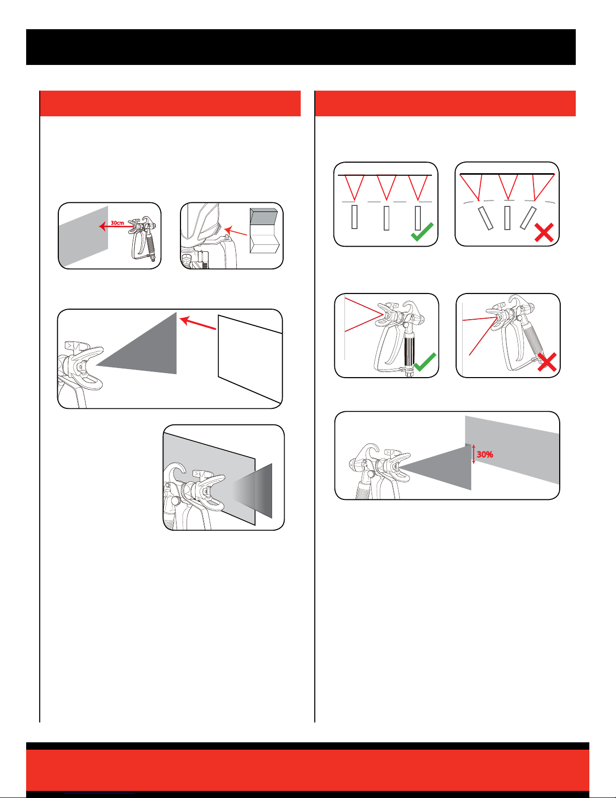
NEVER under any circumstances aim the nozzle at another person or animal.
• In the event of an injury occurring, seek medical advice immediately.
• The spray gun must not be used for spraying ammable paints and solvents with a
ash point of less than 21ºC.
• Always ensure there is adequate ventilation when spraying.
• The use of ear protection is recommended.
• Eye protection is recommended to keep hazardous vapours and liquids out of eyes.
• Always wear a face mask when spraying.
• Always read the paint manufacturers thinning instructions before using.
• Always keep the spray basket nozzle in place during use. Never allow the spray to
come in direct contact with the skin.
WARNING!
DANGER! Never immerse the spray gun in liquid. This could lead to electric shock,
personal injury and material damage.
• The spray gun must not be cleaned by using ammable liquids with a ash point of
less than 21ºC.
NEVER spray near a naked ame, including an appliance pilot light.
NEVER smoke whilst spraying.
NEVER allow children to operate or play with the spray gun.
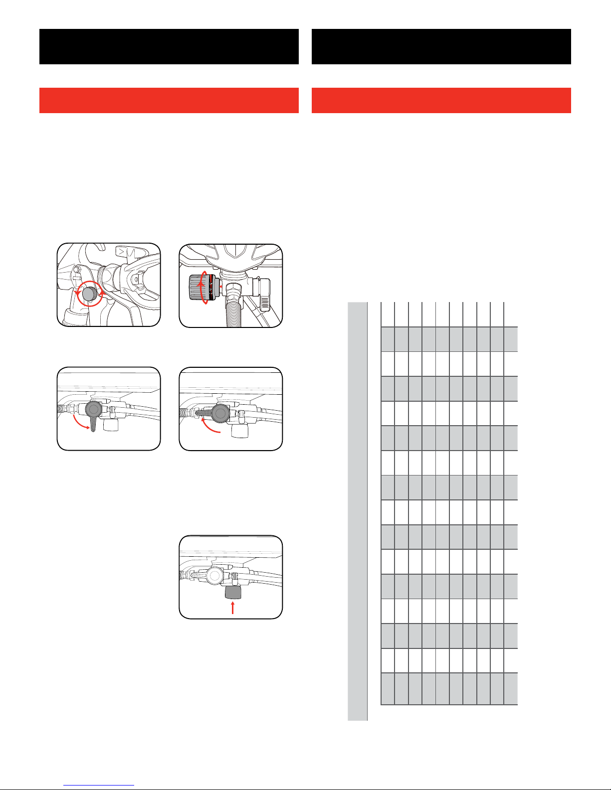
• Before cleaning, always disconnect the appliance from the mains supply.
• Always disconnect from mains supply when relling the paint pot.
• After every use ensure you clean your spray gun thoroughly.
NEVER use the spray gun outside when it is raining.
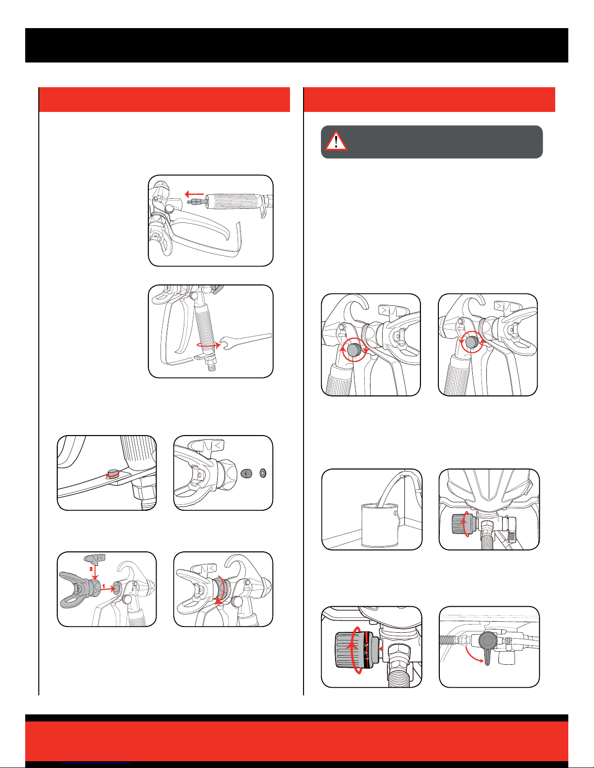
WARNING!
The ASG-6000 Airless Spray Gun operates at very high pressure. For safe
operation the following must be observed at all times.
• Do not point the spray gun at yourself or any other person. Injury from penetration
to the skin and paint solvents being injected into the body can result.
• Always check for leaks and correct operation before use. Never operate the spray
gun if there are any leaks or faults. Faults or leaks can cause injury.
• Release the pressure when not in use. Pressure can remain in the unit and hose
when switched off.
Injury where paint or solvent injection into the skin or body occurs can be very
serious. Always seek professional medical help and advise the paints or solvents
used.
NEVER use the spray gun without the trigger safety guard tted.
WARNING! When using mains-powered tools, basic safety precautions, including the
following, should always be followed to reduce risk of re, electric shock, personal injury
and material damage.
Read the whole manual carefully and make sure you know how to switch the tool off in an emergency, before
operating the tool.
Save these instructions and other documents supplied with this tool for future reference.
The electric motor has been designed for 230V and 240V only. Always check that the power supply
corresponds to the voltage on the rating plate.
Note: The supply of 230V and 240V on Ozito tools are interchangeable for Australia and New Zealand.
If the supply cord is damaged, it must be replaced by an electrician or a power tool repairer in order to avoid
a hazard.
If operating a power tool in a damp location is unavoidable, use a residual current device (RCD) protected
supply. Use a RCD reduces the risk of electric shock.
Using an Extension Lead
Always use an approved extension lead suitable for the power input of this tool. Before use, inspect the
extension lead for signs of damage, wear and ageing. Replace the extension lead if damaged or defective.
When using an extension lead on a reel, always unwind the lead completely. Use of an extension lead not
suitable for the power input of the tool or which is damaged or defective may result in a risk of re and electric
shock.
WARNING! Read all safety warnings and all instructions. Failure to follow the warnings and
instructions may result in electric shock, re and/or serious injury.
Save all warnings and instructions for future reference. The term “power tool” in the warnings refers
to your mains-operated (corded) power tool or battery-operated (cordless) power tool.
1. Work area safety
a. Keep work area clean and well lit. Cluttered or dark areas invite accidents.
b. Do not operate power tools in explosive atmospheres, such as in the presence of ammable
liquids, gases or dust. Power tools create sparks
which may ignite the dust or fumes.
c. Keep children and bystanders away while operating a power tool. Distractions can cause you to lose
control.
2. Electrical safety
a. Power tool plugs must match the outlet. Never modify the plug in any way.
Do not use any adapter plugs with earthed (grounded) power tools. Unmodied plugs and matching
outlets will reduce risk of electric shock.
b. Avoid body contact with earthed or grounded surfaces, such as pipes, radiators, ranges and
refrigerators. There is an increased risk of electric shock
if your body is earthed or grounded.
c. Do not expose power tools to rain or wet conditions. Water entering a power tool will increase the
risk of electric shock.
d. Do not abuse the cord. Never use the cord for carrying, pulling or unplugging the power tool.
Keep cord away from heat, oil, sharp edges or moving parts. Damaged or entangled cords increase
the risk of electric shock.
e. When operating a power tool outdoors, use an extension cord suitable
for outdoor use. Use of a cord suitable for outdoor use reduces the risk of electric shock.
f. If operating a power tool in a damp location is unavoidable, use a residual current device (RCD)
protected supply. Use of an RCD reduces the risk of electric shock.
3. Personal safety
a. Stay alert, watch what you are doing and use common sense when operating a power tool. Do
not use a power tool while you are tired or under the inuence of drugs, alcohol or medication. A
moment of inattention while operating power tools may result in serious personal injury.
b. Use personal protective equipment. Always wear eye protection. Protective equipment such as dust
mask, non-skid safety shoes, hard hat, or hearing protection used for appropriate conditions will reduce
personal injuries.
c. Prevent unintentional starting. Ensure the switch is in the off-position before connecting to power
source and/or battery pack, picking up or carrying the tool. Carrying power tools with your nger on
the switch or energising power tools that have the switch on invites accidents.
d. Remove any adjusting key or wrench before turning the power tool on.
A wrench or a key left attached to a rotating part of the power tool may result
in personal injury.
e. Do not overreach. Keep proper footing and balance at all times. This enables better control of the
power tool in unexpected situations.
f. Dress properly. Do not wear loose clothing or jewellery. Keep your hair, clothing and gloves away
from moving parts. Loose clothes, jewellery or long hair can be caught in moving parts.
g. If devices are provided for the connection of dust extraction and collection facilities, ensure these
are connected and properly used. Use of dust collection can reduce dust-related hazards.
4. Power tool use and care
a. Do not force the power tool. Use the correct power tool for your application. The correct power tool
will do the job better and safer at the rate for which it was designed.
b. Do not use the power tool if the switch does not turn it on and off. Any power tool that cannot be
controlled with the switch is dangerous and must be repaired.
c. Disconnect the plug from the power source and/or the battery pack from the power tool before
making any adjustments, changing accessories, or storing power tools. Such preventive safety
measures reduce the risk of starting the power tool accidentally.
d. Store idle power tools out of the reach of children and do not allow persons unfamiliar with the
power tool or these instructions to operate the power tool. Power tools are dangerous in the hands
of untrained users.
e. Maintain power tools. Check for misalignment or binding of moving parts, breakage of parts and
any other condition that may affect the power tool’s operation. If damaged, have the power tool
repaired before use. Many accidents are caused by poorly maintained power tools.
f. Keep cutting tools sharp and clean. Properly maintained cutting tools with sharp cutting edges are less
likely to bind and are easier to control.
g. Use the power tool, accessories and tool bits etc. in accordance with these instructions, taking
into account the working conditions and the work to be performed. Use of the power tool for
operations different from those intended could result in a hazardous situation.
5. Service
a. Have your power tool serviced by a qualied repair person using only identical replacement parts.
This will ensure that the safety of the power tool
is maintained.
GENERAL POWER TOOL SAFETY WARNINGS
ELECTRICAL SAFETY
AIRLESS SPRAY GUN SAFETY WARNINGS

0916
AIRLESS
PAINT
SPRAYER
650W
Cleaning Manual
This cleaning process must be followed immediately after use to prevent paint from
drying inside the pump and hose. Failure to follow this instruction may permanently
seize the paint sprayer.

1 Turn trigger safety lock on.
Follow this procedure diligently as a build-up of dried paint on the
operating components can stop the unit from working.
3 Turn off pump and then put priming lever into prime position.
Spray Position
Prime Position
2 Adjust the pressure control dial
to cleaning setting.
4 Unlock the trigger and squeeze trigger to release any remaining
pressure in gun.
PRESSURE RELEASE PROCEDURE
CONTENTS
Know Your Product.................................................................. Page 2
Pressure Release Procedure.................................................. Page 3
Acrylic Vs Oil Based................................................................ Page 4
Cleaning the Unit .................................................................... Page 4
Cleaning the Inlet Hose............................................................Page 6
Cleaning the Spray Gun.......................................................... Page 6
Storage.................................................................................... Page 8
Spare Parts............................................................................. Page 8
1 Pressure Control Dial
2 Stand
3 Inlet Return Pipe
4 Paint Outlet
5 Filter
6 Inlet Hose
7 Priming Lever
8 On/Off Switch
9 Carry Handle
10 Nozzle Tip
11 Spray Gun
12 High Pressure Hose
13 Spray Gun Filter
14 Spanner x 2
15 Hex Key
16 Fine Needle x 3
17 Cleaning Brush
AIRLESS SPRAY GUN
KNOW YOUR PRODUCT
WARNING! BEFORE BEGINNING THE CLEANING PROCESS, ENSURE THE
PRESSURE RELEASE PROCEDURE BELOW IS PERFORMED.
Back-up Pressure Release
If the priming lever fails to
reduce pressure in the system,
press the button located
underneath the paint outlet to
release the suction pressure.

THE UNIT
INLET HOSE
RETURN HOSE
3 Aim the spray gun into an empty bucket or container.
Squeeze and hold the spray gun trigger until most of
the paint is removed from the high pressure hose.
Note: Before beginning cleaning procedure ensure the pressure control dial is set to clean/
prime setting and the priming lever is in the spray position.
1 Place the inlet hose into a bucket of appropriate
cleaning solution. Place the return hose into an empty
bucket or container.
2 Turn the unit on, ensuring the priming lever is set to
prime. Check the return hose and wait for a constant
stream of cleaning solution to pass out of it. Then set
the priming lever to the spray position.
4 Lock the spray gun trigger. Rotate the spray tip 180° to the cleaning side. Unlock the
spray gun trigger. Squeeze and hold the spray gun trigger to spray the cleaning solution
through the system.
For Water Based Cleaning
We recommend the use of 10-15 litres when performing the cleaning procedure.
For Oil Based Cleaning
We recommend 1-2 litres of the appropriate solvent based cleaner when performing the
cleaning procedure.
I
O
Note: If you have not nished painting with your airless sprayer and want to take a short
break (30-60 minutes), do not leave paint sitting inside the pump. Perform steps 3-5 above
to prevent paint from drying inside the pump & hose.
Note: Mineral Turpentine SHOULD NOT be mixed with water at any stage during the
cleaning process.
Once you’re ready to begin work again simply follow the spraying instructions in the user
manual. Once properly primed again, aim the spray gun into a waste bucket and allow 30
seconds for any leftover cleaning solution to be ushed out of the system. Then resume
painting as normal.
Note: If the cleaning solution bucket becomes cloudy with paint during cleaning, skip to
section: Cleaning of the inlet hose. Once the inlet lter and hose are clean, re-assemble
them and repeat steps 3-6.
Note: This cleaning process must be followed
immediately after use to prevent paint from drying inside
the pump and hose. Failure to follow this instruction
may permanently seize the paint sprayer.
5 Continue this process until only cleaning solution is ejected from the spray tip. Add
more cleaning solution if all of the paint has not been removed.
6 Move the priming lever to the priming position. Then
switch the unit off and disconnect it from the power
supply.
ACRYLIC VS OIL BASED
If coating material was water based (acrylic paint), use ONLY water when performing the cleaning
procedure. Use of solvent based cleaning materials on water based paints will result in a new
substance that will be extremely difcult to clean.
If coating material was oil based (enamel paint, lacquer etc.) use ONLY the appropriate cleaning
solution. Read the cleaning instructions printed on the coating material’s label to determine which
cleaning material you need. The following solvent based cleaning products are safe to use in the
airless paint sprayer:
• Mineral Turpentine
• Paint Thinner

THE INLET HOSE
1 Squeeze the tabs on the inlet hose clamp
together and slide the hose clamp away
from the lter.
2 Pull the lter out and rinse under
appropriate cleaning solution.
THE SPRAY GUN
1 Remove the spray gun from the high
pressure hose by loosening the nut with a
19mm spanner.
2 Remove the nozzle guard and spray tip
by loosening the retaining nut. Once the
guard assembly has been removed, pull
the nozzle tip out.
3 Using a 3mm hex key and spanner, remove the
trigger guard by loosening and removing the nut
and bolt used to locate it. Slide the tab out of its
groove to free the trigger guard.
1
2
4 While holding the upper part of the spray
gun, loosen the handle by applying a
21mm spanner to the grooves located
on the bottom part of the handle. Rotate
anticlockwise until the handle can be
completely removed.
Note: A small spacer and washer are used to locate the
nozzle tip within the guard. Be careful not to lose these
components when the nozzle guard is removed.
Tip: Using a shifter or bench vice to hold the upper part of the spray gun will make this step
much easier.
5 Remove the mesh lter
from the handle and
clean all components in
the cleaning solution.
Note: After cleaning, inspect the condition of the lter. If the mesh is clogged with dried paint,
has started fraying or has deformed out of shape it will need to be replaced.
Note: If nozzle tip is blocked, use
provided needles by inserting into
the nozzle tip.
7 Follow this procedure in reverse to re-assemble the spray gun.
6 To clean the mesh lter, unscrew either cap end by turning anti-clockwise. Once
unscrewed, remove the cap and pull the other cap and spring out of the mesh lter sleeve.
Use the provided brush to scrub the inside of the mesh lter.
Note: If lter cannot be cleaned it must be replaced.
WARNING! ENSURE THE UNIT IS OFF AND THE PRESSURE RELEASE
PROCEDURE HAS BEEN PERFORMED.

SPARE PARTS
Spare parts can be ordered from the Special Orders Desk
at your local Bunnings Warehouse.
For further information, or any parts not listed here, visit
www.ozito.com.au or contact Ozito Customer Service:
Australia 1800 069 486
New Zealand 0508 069 486
E-mail: [email protected]
Spray Gun SPASG6000-127
Filter (inlet hose) SPASG6000-031
High Pressure Hose SPASG6000-128
Filter (spray gun) SPASG6000-12709
Spray Guard Assembly SPASG6000-12741A
Spray Tip SPASG6000-12738
Tip Guard Seal SPASG6000-12737A
Bleeder Valve Assembly SPASG6000-010A
Pressure Relief Valve Assembly SPASG6000-019A
Pump Column Assembly SPASG6000-060A
Pressure Regulating Valve Assembly SPASG6000-071A
Note: There are a range of lters available to suit specic types of coating materials.
To order a lter to suit your coating material please contact Ozito Customer Service.
Should an issue arise with your Airless Paint Sprayer or if you wish to make a claim
under the 1 year Replacement Warranty, please call our Customer Service Helpline
prior to returning your product.
STORAGE
Once you have completed the cleaning procedure, it is important to protect
the internal components of the pump before it is stored away. Failure to do
so may result in premature wear and corrosion of the pump and various
other components in your Airless Paint Sprayer. We recommend Wagner All
Guard Pump Protector, available from Bunnings Warehouse.
Refer to the manufacturer’s instructions for use and follow accordingly.
Other manuals for ASG-6000
1
Table of contents
Other Ozito Paint Sprayer manuals

Ozito
Ozito SGP-300 User manual

Ozito
Ozito SGP-5000 User manual

Ozito
Ozito PXCWSS-018 User manual

Ozito
Ozito PXWSS-750 User manual

Ozito
Ozito Power X Change PXOSGS-018 User manual

Ozito
Ozito ASG-LPR User manual

Ozito
Ozito PSS-7000U User manual

Ozito
Ozito MPS-700 User manual

Ozito
Ozito ATK-005 User manual

Ozito
Ozito SGP-300 User manual