CAUTION: PLEASE FOLLOW THIS INSTRUCTION MANUAL CAREFULLY TO
PREVENT ANY INJURIES OR COMPLICATIONS THAT MAY ARISE.
Before installing or maintaining the luminary, make sure all power is
WARNING:
.TURNED OFF
Verify that supply voltage is correct by comparing it with the label information on all
fixtures.
Make all connections in accordance with the NEC requirements, and make sure all
luminaries are properly secured to prevent any wire complications. This luminary is
to always be installed with the lens facing down and it is not to exceed the
maximum ambient temperature rating noted on the specification sheet.
FALC Series LED Area Light Installation Guide
Need
help?
T
ech
help
line:
(800) 988-6386 Email: [email protected] Website: www.paclights.comCopyright © 2020 PacLights All Rights Reserved Note: Instructions are subject to change at any time without notice
FALC200, FALC240, FALC300 FALC080, FALC100, FALC150
02-00041-20423
Page 1 of 7
Connect the ACL and the ACN from the FALC Fixture to the conduit with the AC Power Supply Cable. Follow the Wiring Diagram provided.
AC Power Supply
GROUND [GREEN]
NEUTRAL [WHITE]
HOT [BLACK]
INPUT
FALC FIXTURE
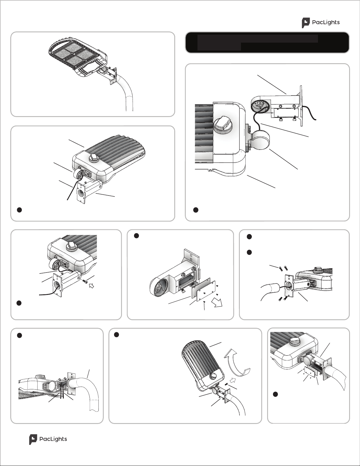
FALC Initial Set-Up
Set the Short-Cap on the NEMA
Receptacle correctly. Install the
Short-Cap provided by pressing down
and twisting CW.
Note: If Photocell Sensor is
provided see the following for
instructions.
The default settings can be changed by adjusting the DIP Switches on the Motion
Sensor. Please refer to the table on this page and also directly on the Motion Sensor.
Turn over the FALC Fixture showing the Lens side. Remove the Screws (4) from
the Shell Cover. Then remove the Shell Cover from the FALC Fixture. The Motion
Sensor is now open to adjust (if needed) the setting. The process is the same for all
FALC-LV-MS fixtures.
Optional Microwave Motion Sensor(FALC-LV-MS ONLY)
1
2
The Integrated Microwave Motion Sensor is a programmable motion detector. This is
only for the FALC-LV-MS models ONLY. The default factory settings are as follows:
Detection Area=100%, Hold Time=5 sec, Stand-By Period=5 sec, Stand-By Dimming
Level=10%, and Daylight (Photo) Sensor=Disable.
Note: If the Microwave Motion Sensor is not included or adjustment is not needed,
the following steps can be skipped.
MOTION
SENSOR
DIP
SWITCHES
FALC-LV
SHELL
COVER
SCREWS
Microwave Motion Sensor DIP Pin Setting
Detection Area
Detection area having motion and not enough ambient light will
activate the sensor. The sensor can be set at 100%, 75%, 50%,
or 10%.
Hold Time
Hold Time refers to the time period the fixture remains at 100%
illumination after motion is detected. Hold Time can range from
5s to 20 minutes. The fixture will remain at full illumination until
‘Hold Time’ ends, then reducing to Stand-By Dimming Level.
Stand-By Period
The Stand-By period begins when the ‘Hold Time’ ends. The
fixture remains at a Stand-By Dimming Level before it completely
switches off while motion is not present. When set to “+∞” mode,
the low led light is held until motion is detected.
Daylight (Photo) Sensor
The Daylight Sensor, measured in LUX can be set to allow the
fixture to illuminate below a surrounding minimum ambient
brightness threshold. The sensor can be set from 2 to 100 LUX.
When set to Disable mode, the Daylight Sensor will switch on
the fixture when motion is detected regardless of ambient light.
Stand-By Dimming Level
Stand-By Dimming Level is when ‘Hold Time’ has ended, there
is no movement in the area and the light output is reduced. The
Stand-By Dimming Level can be set at 50%, 30%, 20%, or 10%.
By selecting the combination on the DIP switches, sensor data can be precisely
set for each specific application as seen below.
+∞
+∞
SHORT-CAP
NEMA
RECEPTACLE
Turn over the FALC Fixture showing the Fin side. All FALC Fixtures
come with a NEMA Seven-Prong Twist Lock receptacle (Compatible with
Three-Prong Photocell Sensors) with Short-Cap to be installed. Remove
the Short-Cap by twisting CCW and lifting.
Optional Photocell Sensor
The Photocell Sensor has a Dusk to Dawn functionality. The Photocell Sensor can be easily field installed on all FALC fixtures as
shown below. Note: If the Photocell Sensor is not included the following steps can be skipped. If the Photocell Sensor is included
prior to field installation, Step 1 can be skipped.
1
Place the Photocell Sensor on the NEMA
receptacle. Push down and twist CW. The
process is the same for all FALC Fixtures.
2
PHOTOCELL
SENSOR
NEMA
RECEPTACLE
NEMA THREE-PRONG
TWIST LOCK PLUG
SHORT-
CAP
Initial Set-up and Optional Controls
2
9
“Initial Set-up and Optional Controls”