1
info@pallighting.com / www.pallighting.com
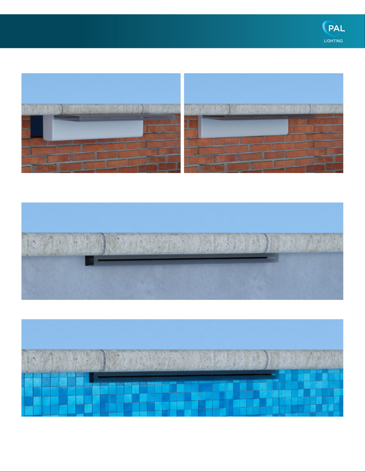
Water Blade Installation Instructions
WARNING - Read and follow all instructions in this owner’s manual and on the equipment. Failure to follow instructions may result in
severe injury and/or death.
WARNING – Suction Entrapment Hazard:
Suction inlets/outlets and/or suction inlet/outlet covers which are damaged, broken, cracked, missing, or unsecured can cause severe
injury and/or death due to the following entrapment hazards:
Hair Entrapment - Hair can become entangled in suction outlet cover.
Limb Entrapment - A limb inserted into an opening of a suction inlet/outlet sump or suction inlet/outlet cover that is damaged, broken,
cracked, missing, or not securely attached can result in a mechanical bind or swelling of the limb.
Body Suction Entrapment - A negative pressure applied to a large portion of the body or limbs can result in an entrapment.
Evisceration/ Disembowelment - A negative pressure applied directly to the intestines through an unprotected suction inlet/
outlet sump or suction inlet/outlet cover which is, damaged, broken, cracked, missing, or unsecured can result in evisceration/
disembowelment.
Mechanical Entrapment - Jewelry, swim-wear, hair decorations, nger, toe or knuckle can be caught in an opening of a suction inlet/
outlet cover resulting in mechanical entrapment.
WARNING - To Reduce the risk of Entrapment Hazards:
• When inlets/outlets are small enough to be blocked by a person, a minimum of two functioning suction outlets per pump must be
installed. Suction inlets/outlets in the same plane (i.e. oor or wall), must be installed a minimum of three feet (3’) [1 meter] apart,
as measured from near point to near point.
• Dual suction ttings must be placed in such locations and distances to avoid “dual blockage” by a user.
• Dual suction ttings must not be located on seating areas or on the backrest for such seating areas.
• The maximum system ow rate shall not exceed 6 ft/sec in the return main line.
• Never use Pool or Spa if any suction inlet/outlet component is damaged, broken, cracked, missing, or not securely attached.
• Replace damaged, broken, cracked, missing, or not securely attached suction outlet components immediately.
• In addition two or more suction outlets per pump installed in accordance with latest ASME, APSP Standards and CPSC guidelines,
follow all National, State, and Local codes applicable.
• Installation of a vacuum release or vent system, which relieves entrapping suction, is recommended.
WARNING – Failure to remove pressure test plugs and/or plugs used in winterization of the pool/spa from the suction outlets can result
in an increase potential for suction entrapment as described above.
WARNING – Failure to keep suction outlet components clear of debris, such as leaves, dirt, hair, paper and other material can result in
an increase potential for suction entrapment as described above.
WARNING – Suction outlet components have a nite life, the cover/grate should be inspected frequently and replaced at least every ten
years or if found to be damaged, broken, cracked, missing, or not securely attached.
CAUTION – Components such as the ltration system, pumps and heater must be positioned so as to prevent their
being used as means of access to the pool by young children. To reduce risk of injury, do not permit children to use or climb
on this product. Closely supervise children at all times. Components such as the ltration system, pumps, and heaters must be
positioned to prevent children from using them as a means of access to the pool.
WARNING – Hazardous Pressure. Pool and spa water circulation systems operate under hazardous pressure during
start up, normal operation, and after pump shut o. Stand clear of circulation system equipment during pump start up. Failure to follow
safety and operation instructions could result in violent separation of the pump housing and cover, and/or lter housing and clamp due
to pressure in the system, which could cause property damage, severe personal injury, or death. Before servicing pool and spa water
circulation system, all system and pump controls must be in o position and lter manual air relief valve must be in open position.
Before starting system pump, all system valves must be set in a position to allow system water to return back to the pool. Do not change
lter control valve position while system pump is running. Before starting system pump, fully open lter manual air relief valve. Do not
close lter manual air relief valve until a steady stream of water (not air or air and water) is discharged.
WARNING – Separation Hazard. Failure to follow safety and operation instructions could result in violent separation
of pump and/or lter components. Strainer cover must be properly secured to pump housing with strainer cover lock ring. Before
servicing pool and spa circulation system, lters manual air relief valve must be in open position. Do not operate pool and spa
circulation system if a system component is not assembled properly, damaged, or missing. Do not operate pool and spa circulation
system unless lter manual air relief valve body is in locked position in lter upper body. Never operate or test the circulation system
at more than 50 PSI. Do not purge the system with compressed air. Purging the system with compressed air can cause components
to explode, with risk of severe injury or death to anyone nearby. Use only a low pressure (below 5 PSI), high volume blower when air
purging the pump, lter, or piping.
WARNING – Risk of Electric Shock. All electrical wiring MUST be in conformance with applicable local codes, regulations, and the
Canadian Electrical Code, ANSI/NFPA70). Hazardous voltage can shock, burn, and cause death or serious property damage. To
reduce the risk of electric shock, do NOT use an extension cord to connect unit to electric supply. Provide a properly located electrical
receptacle. Before working on any electrical equipment, turn o power supply to the equipment. To reduce the risk of electric shock
replace damaged wiring immediately. Locate conduit to prevent abuse from lawn mowers, hedge trimmers and other equipment. Do
NOT ground to a gas supply line.
WARNING – Risk of Electric Shock Failure to ground all electrical equipment can cause serious or fatal electrical shock hazard. Electrical
ground all electrical equipment before connecting to electrical power supply.