manuals.online logo
Brands
  1. Home
  2. •
  3. Brands
  4. •
  5. Panasonic
  6. •
  7. Accessories
  8. •
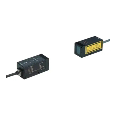
  9. Panasonic LS-400 Series User manual

Panasonic LS-400 Series User manual

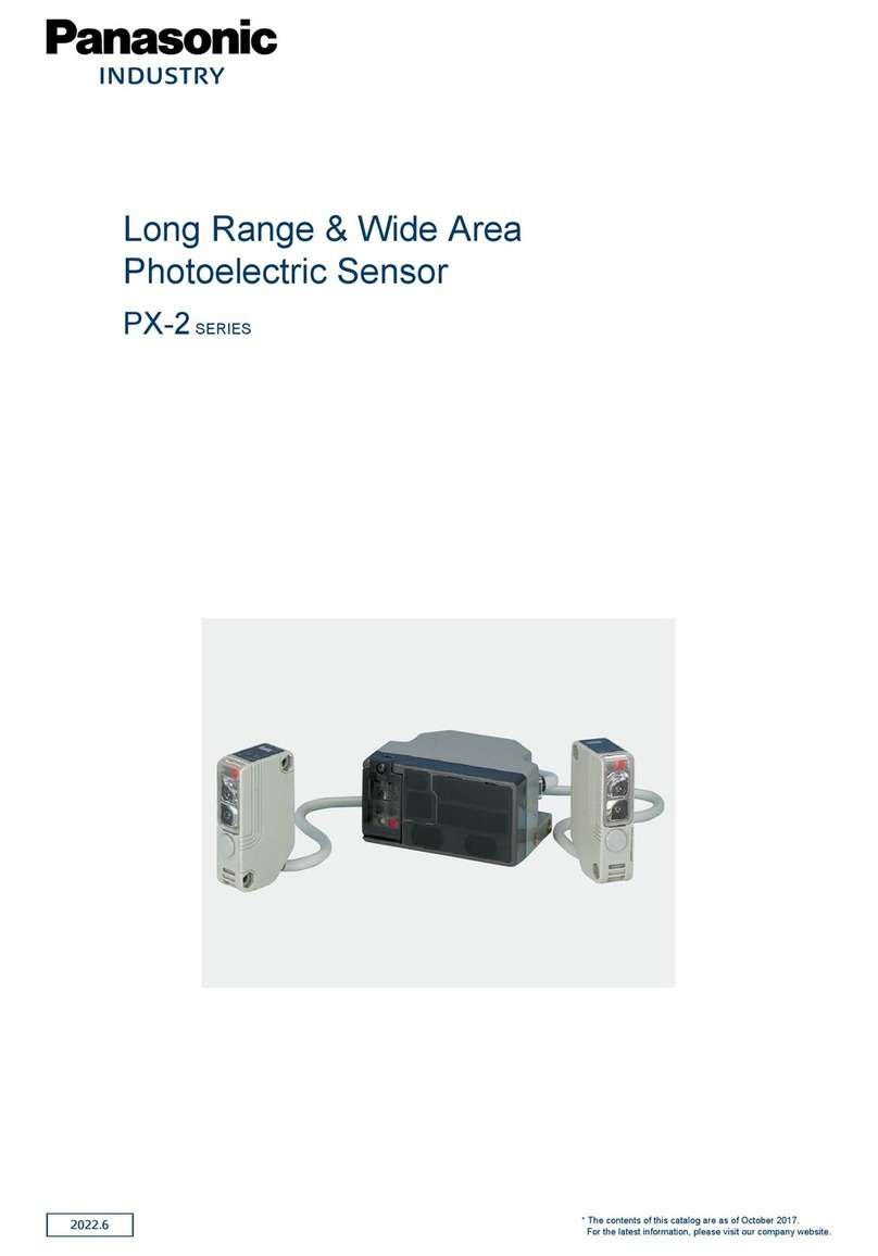
2022.6
Amplifier-separated
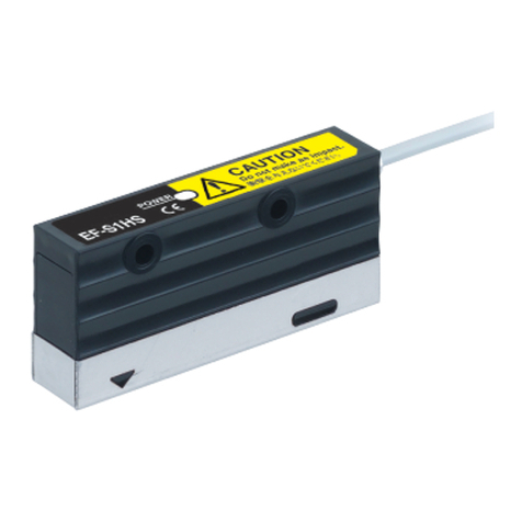
Digital Laser Sensor
LS-400 SERIES
* The contents of this catalog are as of October 2017.
For the latest information, please visit our company website.
2
*This product complies with 21 CFR 1040.10 and
1040.11 Laser Notice No. 50, dated June 24,
2007, issued by CDRH (Center for Devices and
Radiological Health) under the FDA (Food and Drug
Administration).
5 m
(16.404 ft)
1 m
(3.281 ft)
RF-33
RF-31
Compact
reflector
RF-310
RF-230
RF-330
RF-310 RF-330
30 m
(98.425 ft)
7 m
(22.966 ft)
A line width of approx. 240 mm
9.449 in (typical) at a 1,000 mm
39.370 in sensing distance
Long sensing range spot reflective type
LS-H21-A
Long sensing range
coaxial retroreflective type
LS-H92
Connector type
LS-401/401P/403
Cable type (with external input)
LS-401-C2 / LS-401P-C2
Coaxial retroreflective type
LS-H91
Coaxial retroreflective type
LS-H91-A
Amplifiers
Long sensing range line
reflective type LS-H22
Class 1 type
Class 1 type
A spot size of approx. 10 × 8 mm 0.394 × 0.315 in
at a 3 m 9.843 ft sensing distance (Note 2)
A spot diameter of approx.
ø1 mm ø0.039 in at a 1 m
3.281 ft sensing distance (Note 1)
A line width of approx. 115 mm
4.528 in (typical) at a 500 mm
19.685 in sensing distance
Long sensing range
spot reflective type
LS-H21
Easy-to-use sealing-type
reflective tape available
Easy-to-use sealing-type
reflective tape available
500 mm
(19.685 in)
A spot diameter of approx. ø1 mm
ø0.039 in
at a 1,000 mm 39.370 in
sensing distance (Note 1)
Notes: 1) The spot diameter is a typical example. The measurement values given here
were determined with a center light intensity of 1/e
2
(13.5 %).
2) This is the reference value from visual observation.
A spot diameter of approx. ø1 mm
ø0.039 in
at a 1 m 3.281 ft sensing distance (Note 1)
A spot diameter of approx. ø0.2
mm
ø0.008 in
at a 50 mm 1.969
in sensing distance (Note 1)
A spot diameter of approx. ø0.2 mm ø0.008 in
at a 50 mm 1.969 in sensing distance (Note 1)
Digital Laser Sensor Amplier-separated
LS-400 SERIES
User-friendly, high precision
laser sensing!
We offer 6 types of laser sensor heads for various applications
These products are Class 2
(LS-H□-A: Class 1) laser in
compliance with IEC / JIS
/ GB standards and FDA*
regulations Do not look at the
laser beam directly or through
optical system such as a lens.
Conforming to
FDA regulations
(LS-H□F only)
Recognition
(Excluding LS-403)
Certified
(Some models only)
Interference
prevention
A
utomatic
sensitivity setting
Test input
Timer
Light intensity
monitor
PNP output
type available
Digital Laser Sensor LS-400 SERIES
3
APPLICATIONS
LS-H22
Transparent filmsTransparent films
LS-H91
Reflector
Sheet rolls
The coaxial retroreective sensor with a spot diameter
of approx. ø1 mm ø0.039 in (at a 1 m 3.281 ft sensing
distance), can measure amounts remaining on sheet rolls
with high precision.
LS-H21
Industry standard mounting pitch
The mounting pitch for sensor heads is
25.4 mm 1.000 in, the same industry standard as the
CX-400 series Ver.2 general purpose photoelectric
sensors. Hence, existing mounting brackets can be used
even when replacing general purpose sensors with laser
sensors.
11.2 mm 0.441 in
General purpose photoelectric
sensor CX-400 series Ver.2
Long sensing range line reflective type: LS-H22
Long sensing range spot reflective type: LS-H21(-A)
Coaxial retroreflective type: LS-H91
(-A)
, LS-H92
Industry standard
mounting pitch
25.4mm 1.000 in
Identical shape and mounting
Slim size
NOTE: The applications given in this catalog are examples for reference only. Stable sensing may not be possible under
certain setup conditions and environmental conditions, so be sure to check the actual sensor before use.
Operation indicator
Laser emission indicator
Easy adjustment while
viewing the spot.
The spot shape can be adjusted
according to the object.
Spot-shape adjuster
Spot-shape adjuster
(multiple turn)
Highly reliable built-in multiple
turn-type knob allows you to
adjust the spot shape easily.
Easy and accurate adjustments
A spot-size adjuster is built into the back of the sensor
head allowing the user to adjust the sensor easily while
viewing the spot. The adjuster is adjustable with a
screwdriver to avoid accidents during maintenance or
any other time the sensors are handled.
Long sensing range line reective type
Long sensing range spot reective type
Detecting objects with a complex shape
Detecting the remaining amount of sheet rolls
Detecting electronic component pins
Line-up of FDA / IEC / JIS
Class 1 type
LS-H91(F)-A, LS-H21(F)-A
Visible light spot using the Class 1 type.
This makes beam axis alignment much easier.
Sensor mounting bracket for beam axis
alignment is available
MS-CX-11
It is possible to make a minor adjustment for the bracket
by 4 degrees up, down, right or left, even after setting
up the sensor. The bracket can be mounted in both
longitudinal and lateral directions.
Vertical
adjustment
screw
Horizontal
adjustment screw
Hole for the
foot angled
mounting
bracket
Hole for the foot
biangled mounting bracket
4 degrees
right and left
4 degrees up and down
MS-CX-11
Sensor mounting bracket
for beam axis alignment
Sensor mounting bracket
for beam axis alignment
Its linear sensing area enables more
stable detection of objects with complex
shapes.
Because its spot shape can be adjusted in accordance
with the object, it can be easily set to detect even the
minutest object from a remote location.
4
Digital Laser Sensor LS-400 SERIES
Easy setting, dual display
Equipped with 2 large 4-digit digital displays. While checking the current incident light intensity (red display), the
optimal threshold value (green display) can be set easily.
10 mm 0.394 in
thickness
Large jog switchThreshold value setting display
Green LED, 4 digits (Max. display: 9999)
Current incident light intensity display
Red LED, 4 digits (Max. display: 9999)
Large MODE key
2 switches enable simple operation
Only two switches, the large MODE key and the large jog switch, are required for operation.
3
Pressing the switch
selects or cancels the
operating mode
Moving the switch from
side to side allows items
to be selected
Pressing the switch then
confirms the selected
setting
2
1
Threshold tracking function saves
maintenance time
This function seeks
changes in the light emitting
amount resulting from
changes in the environment
over long periods (such
as dust levels), so that
the incident light intensity
can be checked at desired
intervals and the threshold
values can be reset
automatically. This helps to
reduce the man-hours for
maintenance.
Time
Current value
The amount of light
received when there
is no object
Incident light intensity
Threshold value
Digital fiber sensor
FX-500/300 series
Digital pressure sensor
DPS-400 series
Up to 16 units can be
connected together
Note: Because the transmission method varies depending on the
amplifiers, check the instruction manual for the amplifiers when
connecting them.
Wiring and space saving
The quick-connection cables enable reductions in wiring.
(connector type)
The connections and man-hours for the relay terminal
setup can be reduced and valuable space is saved.
Also, LS-400 series ampliers can of course be
connected side-by-side with a connector type amplier
of FX-500/300 series digital ber sensors or DPS-400
series digital pressure sensors.
Note: Because the transmission method varies depending on the
ampliers, check the instruction manual for the ampliers when
connecting them.
*
CC-Link and CC-Link IE Field are a registered trademark of
Mitsubishi Electric Corporation.
DeviceNet is a registered trademark of ODVA (Open DeviceNet
Vender Association, Inc.).
EtherCAT is a registered trademark of Beckhoff Automation GmbH.
New release of type with upper communication functions to facilitate preventive maintenance!
LS-403
Network communication possible
Can connect to Open Network CC-Link IE Field /
CC-Link / DeviceNet / EtherCAT via Communication
Unit for Open Network SC-GU3 series. Monitoring and
various settings can be done from PLC, PC, etc.
しきい 値
1ch
現在値
90 65
2ch 50 0
3ch 40 70
4ch 00
5ch 00
6ch 00
7ch 00
8ch 00
しきい 値
9ch
現在値
00
10ch 00
11ch 00
12ch 00
13ch 00
14ch 00
15ch 00
16ch 00
LS-403/501
FX-501/502
FX-301/305
DPS
-
401/402
Current values
of connected
sensors are
shown.
[Touch panel display example]
Threshold values of
connected sensors are
shown.
End unit
Digital laser sensor
Digital fiber sensor
Digital pressure sensor
Communication Unit
for Open Network
SC-GU3
series
First digit:
Output operation
Second digit:
Ti
mer operation
Eighth digit:
Sensing mode
Fifth digit:
Hysteresis
Third digit:
Response time Seventh digit:
Customized function
Fourth digit:
M.G.S. function
Sixth digit:
External input mode
The sensitivity can be changed
without changing the response time.
Receiving sensitivity: High
Receiving sensitivity: Medium
Receiving sensitivity: Low
By adjusting the hysteresis,
convexo-concave parts of uneven
objects can be cancelled enabling
more stable sensing.
The sensor judges any object
outside the range of incident light
intensity established by two set
threshold values.
Hysteresis mode Window comparator mode
By combining two outputs, wide
array of control is possible, allowing
you to detect meandering objects,
for example.
Only rapid changes in light received
are detected, which enable the edge of
glass, etc. to be detected accurately.
Optimal for positioning.
2 independent output modes Differential sensing mode
OK
NG: Over range
NG: Under range
ON
OUT1
OFF
Incident light intensity
To left
To right
ON
OUT2
OFF
OK
4 new modes enabling wide array of sensing
MODE NAVI customized function
Frequently used functions such as response time,
M.G.S. function, data bank load, emission halt function
and D-CODE values can be stored in CUSTOM mode.
The settings are changed easily.
Emission halt function
If you do not want to
place a laser spot in
the visual range of
the image processor,
you can stop the laser
radiation using the
emission halt signal
from the external input.
Cable type allows external input
The LS-401-C2 cable-type amplier is equipped with an
external input wire (5-core). It is ideal to use the laser
sensor at places where external teaching or laser light
emission halting is to be carried out, or at the places
where the laser sensor is to be used separately.
Interference prevention function
The automatic interference
prevention function prevents
against interference among
up to 4 sensors.
Setting conditions viewed at a glance (D-CODE)
The amplier setting is shown as an 8-digit code. Handy
for remote indications and follow-ups.
Accurately sense the minutest variations
(M.G.S. function)
When sensing at close range or when the target objects
are transparent or minute, adjust the sensor receiving
sensitivity to one of 3 levels (U-LG mode: 4 levels) for
the optimal setting. In addition, changing the receiving
sensitivity will not effect the response time.
CUSTOM mode
Response time
M.G.S. function
Data bank load
Emission halt function
D-CODE
2 m 6.562 ft cable
attached
•
Laser emission halt
•Teaching
External input
5
Digital Laser Sensor LS-400 SERIES

Other manuals for LS-400 Series

3

This manual suits for next models

5

Other Panasonic Accessories manuals

Panasonic MA2YF80 User manual

Panasonic

Panasonic MA2YF80 User manual

Panasonic MA3J702 User manual

Panasonic

Panasonic MA3J702 User manual

Panasonic Light Emitting Diodes LNJ414K8YRA User manual

Panasonic

Panasonic Light Emitting Diodes LNJ414K8YRA User manual

Panasonic MA2J1150G User manual

Panasonic

Panasonic MA2J1150G User manual

Panasonic MALHxxxYG Series User manual

Panasonic

Panasonic MALHxxxYG Series User manual

Panasonic HL-C201A-SP3 User manual

Panasonic

Panasonic HL-C201A-SP3 User manual

Panasonic SP Series Guide

Panasonic

Panasonic SP Series Guide

Panasonic HG-S Series User manual

Panasonic

Panasonic HG-S Series User manual

Panasonic LS-400 Series User manual

Panasonic

Panasonic LS-400 Series User manual

Panasonic HL-C2 Series User manual

Panasonic

Panasonic HL-C2 Series User manual

Panasonic MALS180XG User manual

Panasonic

Panasonic MALS180XG User manual

Panasonic Light Emitting Diodes LNJ0F1C5FRA1 User manual

Panasonic

Panasonic Light Emitting Diodes LNJ0F1C5FRA1 User manual

Panasonic MA2J7040G User manual

Panasonic

Panasonic MA2J7040G User manual

Panasonic MA4Z159 User manual

Panasonic

Panasonic MA4Z159 User manual

Panasonic MCO-230AIC User manual

Panasonic

Panasonic MCO-230AIC User manual

Panasonic PX-2 Series User manual

Panasonic

Panasonic PX-2 Series User manual

Panasonic HL-C21C Series User manual

Panasonic

Panasonic HL-C21C Series User manual

Panasonic HG-C Series User manual

Panasonic

Panasonic HG-C Series User manual

Panasonic HL-C2 Series User manual

Panasonic

Panasonic HL-C2 Series User manual

Panasonic HL-C211F-MK User manual

Panasonic

Panasonic HL-C211F-MK User manual

Panasonic MAS3795EG User manual

Panasonic

Panasonic MAS3795EG User manual

Panasonic MA6X125 (MA125) User manual

Panasonic

Panasonic MA6X125 (MA125) User manual

Panasonic MA2J111 (MA111) User manual

Panasonic

Panasonic MA2J111 (MA111) User manual

Panasonic MA22D39 User manual

Panasonic

Panasonic MA22D39 User manual

Popular Accessories manuals by other brands

Quincy lab 140AE-1 operating manual

Quincy lab

Quincy lab 140AE-1 operating manual

HomePro ZIR000 user manual

HomePro

HomePro ZIR000 user manual

DOL 20SCR Technical user guide

DOL

DOL 20SCR Technical user guide

RAB Smart Task installation manual

RAB

RAB Smart Task installation manual

Kemppi KMS 300 quick guide

Kemppi

Kemppi KMS 300 quick guide

Stearns 57,500 Series Installation and service instructions

Stearns

Stearns 57,500 Series Installation and service instructions

iGuzzini TWILIGHT COPENAGHEN manual

iGuzzini

iGuzzini TWILIGHT COPENAGHEN manual

Adelaide Annexe & Canvas Avan Deluxe installation guide

Adelaide Annexe & Canvas

Adelaide Annexe & Canvas Avan Deluxe installation guide

OHAUS 5000 instruction manual

OHAUS

OHAUS 5000 instruction manual

HOME8 WLS1300 quick start guide

HOME8

HOME8 WLS1300 quick start guide

MAXBOTIX MaxSonar quick start guide

MAXBOTIX

MAXBOTIX MaxSonar quick start guide

ioSmart iSmart56 Installation and user guide

ioSmart

ioSmart iSmart56 Installation and user guide

Focusrite Scarlett 18i8 user guide

Focusrite

Focusrite Scarlett 18i8 user guide

Velleman ED38105 user manual

Velleman

Velleman ED38105 user manual

JumpSport SkyBounce user manual

JumpSport

JumpSport SkyBounce user manual

Prima-Temp PRIYA Instructions for use

Prima-Temp

Prima-Temp PRIYA Instructions for use

Tefcold BC85I-BC85I W user manual

Tefcold

Tefcold BC85I-BC85I W user manual

Vaisala WMS302 user guide

Vaisala

Vaisala WMS302 user guide

manuals.online logo
manuals.online logoBrands
  • About & Mission
  • Contact us
  • Privacy Policy
  • Terms and Conditions

Copyright 2025 Manuals.Online. All Rights Reserved.