manuals.online logo
Brands
  1. Home
  2. •
  3. Brands
  4. •
  5. Panasonic
  6. •
  7. Accessories
  8. •
  9. Panasonic PE Series User manual

Panasonic PE Series User manual

SPECIFICATIONS
1
Type Vacuum pressure
-101kPa type
PE-20Z PE-21Z PE-22Z
100kPa type 1MPa type
Positive pressure
Model No.Item
Gauge pressureType of pressure
Non-corrosive gasApplicable fluid
5% F.S. approx.Hysteresis
12 to 24V DCs10% Ripple P-P 10% or lessSupply voltage
Indication with red LED bar plus 1
㸭
2step indicator (Green LED)Pressure display
ON above set pressure level or OFF above set pressure level, selectable with control inputOutput operation
2.5% F.S. or lessDisplay resolution
Incorporated
Short-circuit protection
40mA or lessCurrent consumption
10ms or lessResponse time
Red LED (lights up when the output is ON)Operation indicator
Red LED (lights up when the power is ON)Power indicator
0 to +50Υ(No dew condensation), Storage: -10 to +60ΥAmbient temperature
35 to 85% RH, Storage: 35 to 85% RHAmbient humidity
Over ambient temperature range 0 to +50Υ: within s5% F.S. of detected pressure at +25Υ
Temperature characteristics
R1
㸭
4male thread and M5 female thread
Pressure port
Front case: PBT, Rear case: PBT, Front panel: Polycarbonate, Pressure port: Brass (Nickel plated)
Material
0.18mm24-core cabtyre cable, 0.5m long
Cable
85g approx.
Weight
NPN open-collector transistor
࣭Maximum sink current: 100mA
࣭Applied voltage: 30V DC or less (between output and 0V)
࣭Residual voltage: 1V or less (at 100mA sink current)
0.4V or less (at 16mA sink current)
Output
490kPa 1.47MPaPressure withstandability
0 to -101kPa 0 to 100kPa 0 to 1MPaRated pressure range
-10 to -90kPa 10 to 90kPa 0.1 to 0.9MPaSet pressure range
PIPING
3
ەWhen connecting a coupling to the pressure port,
hold the hexagonal part of the pressure port with a
14mm spanner and make sure that the tightening
torque is under the value shown below.
(Do not apply a spanner on the enclosure.)
The tightening torque should be 20N㺃m or less
with the R1
㸭
4male thread and 2N㺃m or less with
the M5 female thread.
Also, in order to prevent any leakage, wind a sealing tape on the male
thread when connecting.
Male
thread
Female
thread
14mm
spanner
MOUNTING
4
ەThe sensor mounting bracket MS-PE-1 (optional) is available. When
mounting the sensor with the sensor mounting bracket, etc., the tighten-
ing torque should be 0.5N㺃m or less.
ەThe panel mounting bracket MS-PE-2
(optional) and the front protection
cover MS-PE-3 (optional) are also
available.
(Unit: mm)
Sensor mounting bracket
MS-PE-1 (optional)
M3 (length 8mm)
screws with washer
t 2
25 2-ȭ6.4
12
53
25
Front protection cover
MS-PE-3 (optional)
Panel mounting bracket
MS-PE-2 (optional)
Suitable for 1 to 3.2mm
thick panel
Thank you very much for purchasing Panasonic products. Read this Instruc-
tion Manual carefully and thoroughly for the correct and optimum use of this
product. Kindly keep this manual in a convenient place for quick reference.
ە
ە
Never use this product as a sensing device for personnel protection.
In case of using sensing devices for personnel protection, use
products which meet laws and standards, such as OSHA, ANSI
or IEC etc., for personnel protection applicable in each region
or country.
WARNING
CAUTIONS
2
ە
ە
ە
ە
ە
ە
ە
ە
ە
ە
ە
ە
ە
ە
ە
ە
This product has been developed / produced for industrial use only.
Use within the rated pressure range.
Do not apply pressure exceeding the pressure withstandability value.
The diaphragm will get damaged and correct operation shall not be
maintained.
Make sure that the power supply is off while wiring.
Take care that wrong wiring will damage the sensor.
Verify that the supply voltage variation is within the rating.
If power is supplied from a commercial switching regulator, ensure that
the frame ground (F.G.) terminal of the power supply is connected to an
actual ground.
In case noise generating equipment (switching regulator, inverter motor,
etc.) is used in the vicinity of this sensor, connect the frame ground
(F.G.) terminal of the equipment to an actual ground.
Do not use during the initial transient time (50ms) after the power sup-
ply is switched on.
Do not run the wires together with high-voltage lines or power lines or put
them in the same raceway. This can cause malfunction due to induction.
Avoid dust, dirt, and steam.
Take care that the sensor does not come in contact with water, oil,
grease, organic solvents, such as, thinner etc., strong acid or alkaline.
Do not insert wires, etc, into the pressure port. The diaphragm will get
damaged and correct operation shall not be maintained.
Do not operate the keys with pointed or sharp objects.
Make sure that stress by forcible bend or pulling is not applied directly
to the sensor cable joint.
This is a CE conformity product complying with EMC Directive. The
standard with regard to immunity that applies to this product is EN
61000-6-2, and in order to meet the standard, every cable connected to
this product must be within 10m with 0.3mm2, or more, cable. However,
in case CE conformity is not required, the cable length can be up to
100m with 0.3mm2, or more, cable.
PE series is designed for use with non-corrosive gas. It cannot be used
for liquid or corrosive gas.
PE Series SI unit only
LED Bar Display
INSTRUCTION MANUAL
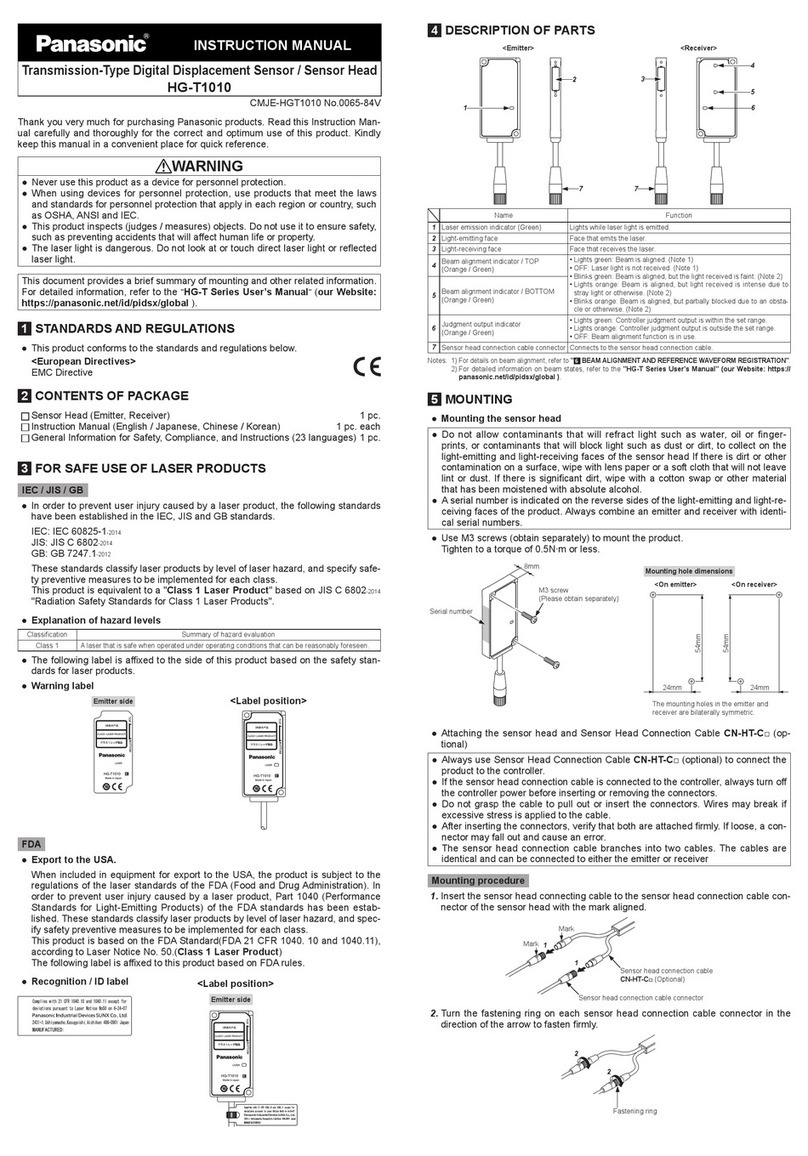
ERROR DISPLAY
6
ە
If the display is as shown in the right figure, excess current
is flowing due to a load short-circuit. In this case, switch off
the power supply and check the load and output.
Note: The right figure shows the vacuum pressure type sensor. In case of the
positive pressure type sensor, the position of the indicators (red) is symmet-
rically opposite.
DIMENSIONS (Unit: mm)
8
Set pressure pointer
40
5.5
40
Set pressure adjuster
Pressure indicator (Red) (Note)
Power indicator (Red)
(Note)
Operation indicator
(Red)
1
㸭
2step indicator (Green)
13
30 13
54
M5 female thread, 6 deep
Pressure port R1
㸭
4male thread
ȭ3.7 cable, 0.5m long
25
14
25
2-M3 female threads,
6 deep
Note: The figure illustrates the indicator position for the positive pressure type sensor.
For the vacuum pressure type sensor, the indicator position is symmetrically opposite.
Symbols ... D
ZD
Tr
: Reverse supply polarity protection diode
: Surge absorption zener diode
: NPN output transistor
I/O CIRCUIT DIAGRAMS
5
*1: Output operation selection by control input
Hysteresis (5% F.S. approx.)
ON
OFF
Set pressure
Low vacuum
(Vacuum pressure)
Low pressure
(Positive pressure)
High vacuum
(Vacuum pressure)
High pressure
(Positive pressure)
0
ĬConnect to +V or open ĭConnect to 0V
Low vacuum
(Vacuum pressure)
Low pressure
(Positive pressure)
High vacuum
(Vacuum pressure)
High pressure
(Positive pressure)
Hysteresis (5% F.S. approx.)
ON
OFF
Set pressure
0
Users' circuitInternal circuit
Color code
100mA max.
+
-
12 to 24V DCs10%
(Brown) +V
(Black) Output
(Pink) Control input
(Blue) 0V
Load
D
ZD
Tr
*1
Main circuit
FUNCTIONAL DESCRIPTION
7
Note:
In case of the vacuum pressure type, the position of the indicators (red) is symmetrically opposite.
Note: It is possible that the position of the set pressure pointer and the position of the pressure indi-
cator lighting up may not match. Use the set pressure pointer as a reference.
kPa
.2
.4 .6
.8
1.0
20
40 60
80
100
PE-21Z
OUT 1/2 STEP
ղSet pressure adjuster
նPressure indicator (Red)
ձSet pressure pointer
մPower indicator (Red)
ճMain scale
յOperation indicator (Red) շ1
㸭
2step indicator (Green)
Designation
ձ
Description
Set pressure pointer
(Note)
Rotating the set pressure adjuster turns the pointer simultaneously.
The value indicated by the pointer represents the set pressure level.
մPower indicator (Red) Lights up when the power is ON.
յ
Operation indicator (Red)
Lights up when the output is ON.
նPressure indicator (Red) Shows the measured pressure level.
ճMain scale
It completely coincide with the LED bar display.
PE-20Z,PE-21Z: kPa
PE-22Z: MPa
շ1
㸭
2step indicator (Green)
By using the 1
㸭
2step indicator in combination with the pressure in-
dicator, the resolution can be increased to twice than that in case
of using the pressure indicator only.
ղSet pressure adjuster
Sets the threshold level.
࣭Rotating it counterclockwise, sets a higher vacuum level.
Vacuum pressure type
࣭Rotating it clockwise, sets a higher positive pressure level.
Positive pressure type
1/2 STEP
.6
.8
1.0
60
80
100
= 80kPa
Turns off
= 82.5kPa
Lights up
1/2 STEP
.6
.8
1.0
60
80
100
(EX.)
INTENDED PRODUCTS FOR CE MARKING
9
ەThe models listed under ' SPECIFICATIONS' come with
CE Marking.
As for all other models, please contact our office.
1
Contact for CE
<Until June 30 ,2013>
Panasonic Electric Works Europe AG
Rudolf-Diesel-Ring 2, D-83607 Holzkirchen, Germany
<From July 1 ,2013>
Panasonic Marketing Europe GmbH Panasonic Testing Center
Winsbergring 15, 22525 Hamburg,Germany
http://panasonic.net/id/pidsx/global
PRINTED IN JAPAN © Panasonic Industrial Devices SUNX Co., Ltd. 2013
Overseas Sales Division (Head Office)
2431-1 Ushiyama-cho, Kasugai-shi, Aichi, 486-0901, Japan
Phone: +81-568-33-7861 FAX: +81-568-33-8591
About our sale network, please visit our website.

This manual suits for next models

3

Other Panasonic Accessories manuals

Panasonic MA Motion Sensor Series User manual

Panasonic

Panasonic MA Motion Sensor Series User manual

Panasonic LNJ0F1C5FRA4 User manual

Panasonic

Panasonic LNJ0F1C5FRA4 User manual

Panasonic CX-400 Series User manual

Panasonic

Panasonic CX-400 Series User manual

Panasonic MA3S132DG User manual

Panasonic

Panasonic MA3S132DG User manual

Panasonic HG-T Series User manual

Panasonic

Panasonic HG-T Series User manual

Panasonic WV-PB5504A User manual

Panasonic

Panasonic WV-PB5504A User manual

Panasonic MA6X124 (MA124) User manual

Panasonic

Panasonic MA6X124 (MA124) User manual

Panasonic PE Series User manual

Panasonic

Panasonic PE Series User manual

Panasonic WX-LA20 Reference manual

Panasonic

Panasonic WX-LA20 Reference manual

Panasonic AG-BS300E User manual

Panasonic

Panasonic AG-BS300E User manual

Panasonic MAS3795EG User manual

Panasonic

Panasonic MAS3795EG User manual

Panasonic MA3J744 (MA744) User manual

Panasonic

Panasonic MA3J744 (MA744) User manual

Panasonic MN34120PAJ User manual

Panasonic

Panasonic MN34120PAJ User manual

Panasonic MA21D382G User manual

Panasonic

Panasonic MA21D382G User manual

Panasonic HL-G1 Series User manual

Panasonic

Panasonic HL-G1 Series User manual

Panasonic TYTP10E User manual

Panasonic

Panasonic TYTP10E User manual

Panasonic ER-VS02 User manual

Panasonic

Panasonic ER-VS02 User manual

Panasonic SL-CH22 User manual

Panasonic

Panasonic SL-CH22 User manual

Panasonic HL-C2 Series User manual

Panasonic

Panasonic HL-C2 Series User manual

Panasonic MA2J1150G User manual

Panasonic

Panasonic MA2J1150G User manual

Panasonic MA4X193 (MA193) User manual

Panasonic

Panasonic MA4X193 (MA193) User manual

Panasonic CA-LSR10U - Sirius Satellite Radio Receiver User manual

Panasonic

Panasonic CA-LSR10U - Sirius Satellite Radio Receiver User manual

Panasonic WX-LA20 User manual

Panasonic

Panasonic WX-LA20 User manual

Panasonic HL-C2 Series User manual

Panasonic

Panasonic HL-C2 Series User manual

Popular Accessories manuals by other brands

REMEHA iBase RF-Base station user manual

REMEHA

REMEHA iBase RF-Base station user manual

Covidien Nellcor MAXA Instructions for use

Covidien

Covidien Nellcor MAXA Instructions for use

Palram SIERRA 2.3x 2.3m/7'5" instructions

Palram

Palram SIERRA 2.3x 2.3m/7'5" instructions

STEINEL IR 180 UP easy manual

STEINEL

STEINEL IR 180 UP easy manual

Triex LLC Filabot Airpath Operator's manual

Triex LLC

Triex LLC Filabot Airpath Operator's manual

Philips HQ4/3P Replacement guide

Philips

Philips HQ4/3P Replacement guide

Baumer UNDK 20N7914/S35A quick start guide

Baumer

Baumer UNDK 20N7914/S35A quick start guide

cabstone PocketPower Series user manual

cabstone

cabstone PocketPower Series user manual

OneVue OneVue Sense  E121 installation guide

OneVue

OneVue OneVue Sense E121 installation guide

WMF Ambient operating manual

WMF

WMF Ambient operating manual

Festo SOOE-RS PNLK-T Series manual

Festo

Festo SOOE-RS PNLK-T Series manual

Xsens DOT user manual

Xsens

Xsens DOT user manual

Amroad AMROAD P3 Technical manual

Amroad

Amroad AMROAD P3 Technical manual

NEARBIRDS ATACMS user manual

NEARBIRDS

NEARBIRDS ATACMS user manual

Newer Technology 20A-TR Power2U user guide

Newer Technology

Newer Technology 20A-TR Power2U user guide

IFM O1D120 operating instructions

IFM

IFM O1D120 operating instructions

ELRO AS90PLE user manual

ELRO

ELRO AS90PLE user manual

Telrad BreezeCOMPACT System manual

Telrad

Telrad BreezeCOMPACT System manual

manuals.online logo
manuals.online logoBrands
  • About & Mission
  • Contact us
  • Privacy Policy
  • Terms and Conditions

Copyright 2025 Manuals.Online. All Rights Reserved.