English/ Español
Scan QR Code for Full Guide
Escanee QR para guía completa
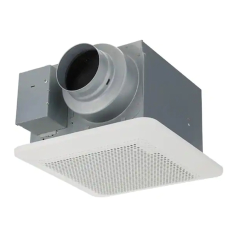
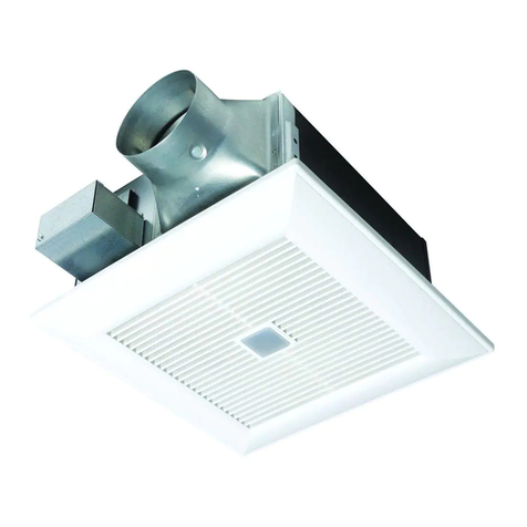
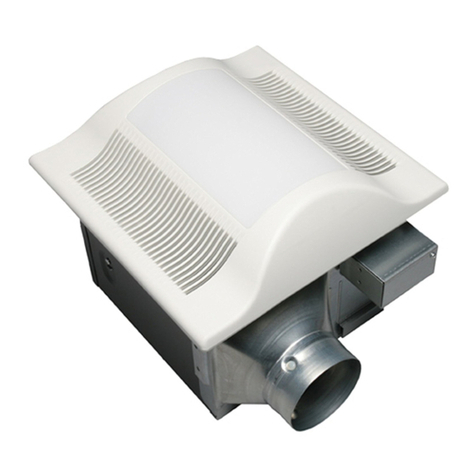
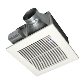
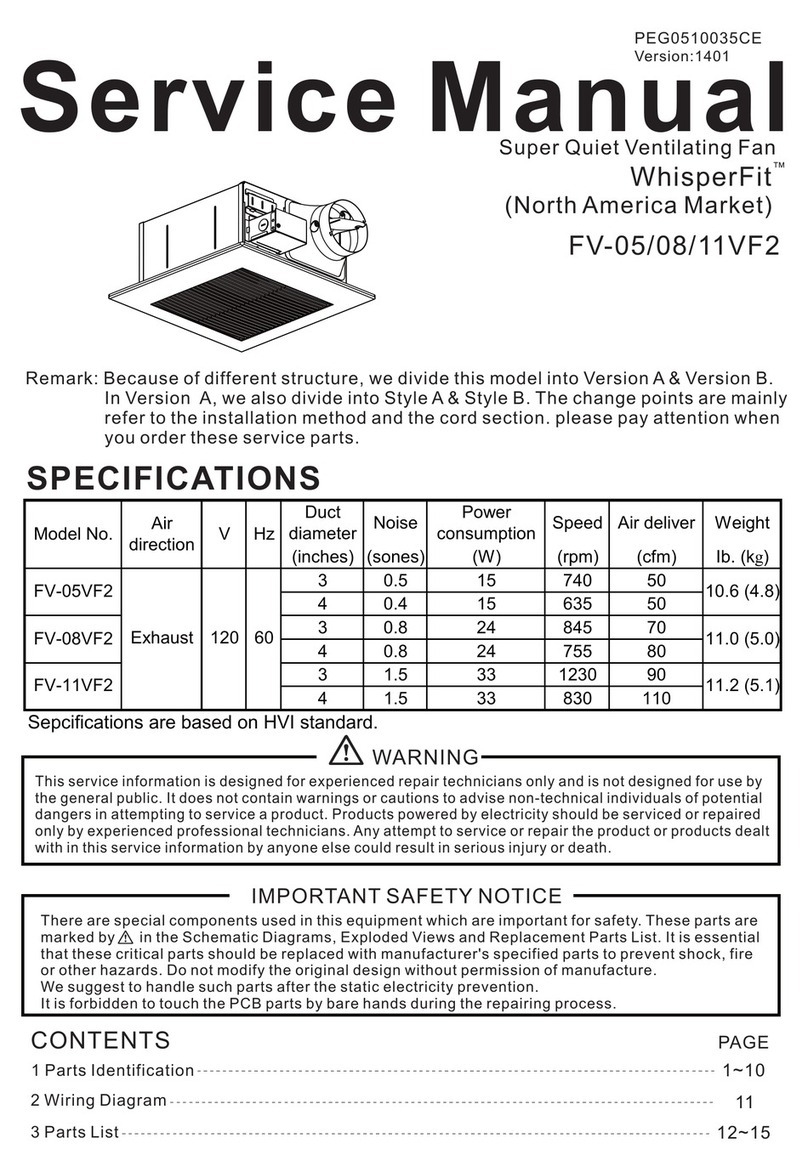
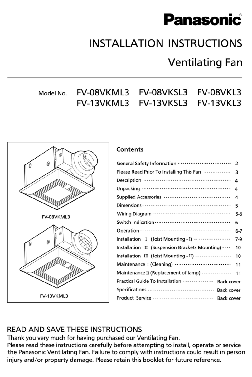
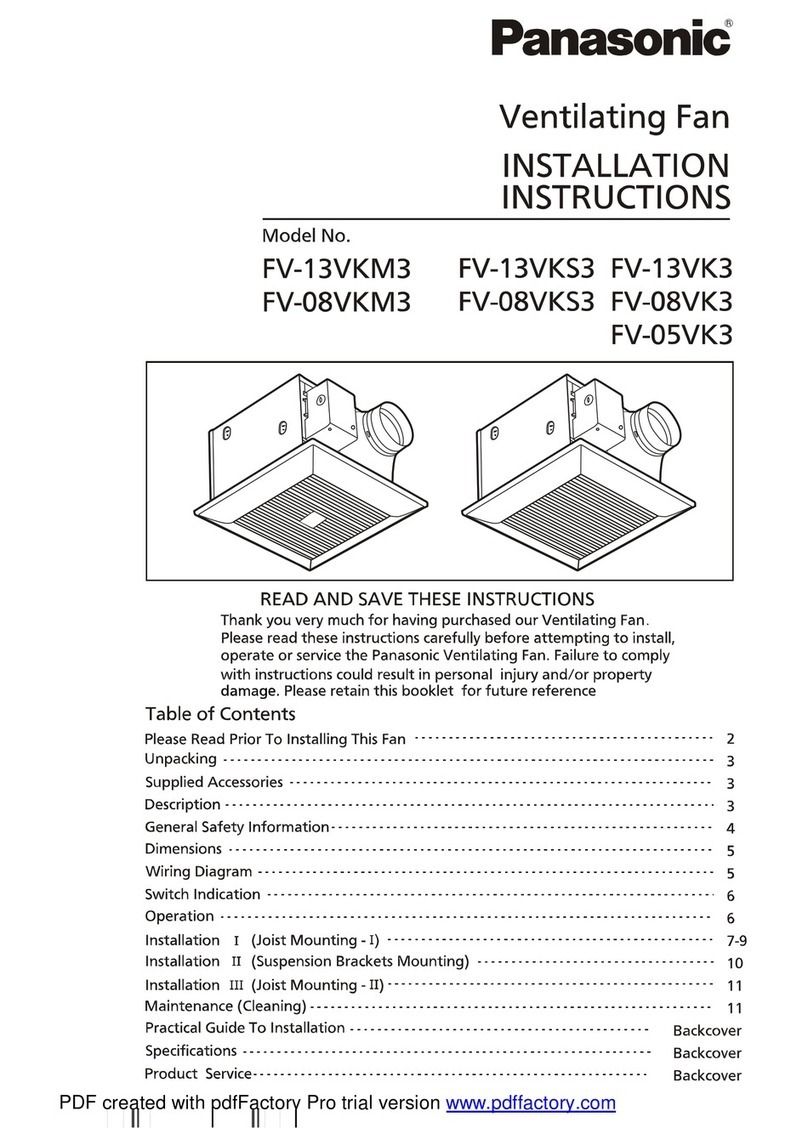
Ventilating Fan/Ventilador
Denotes a hazard
that could result in
minor injury.
Denotes a hazard that could
result in property damage.
READ AND SAVE THESE INSTRUCTIONS LEA Y CONSERVE ESTAS INSTRUCCIONES
2
WARNING
4. Sufficient air is needed for proper combustion and
exhausting of gases through the flue (chimney) of fuel
burning equipment to prevent back-draft. Follow the
heating equipment manufacturer’s guideline and safety
standards such as those published by the National Fire
Protection Association (NFPA), and the American
Society of Heating, Refrigerating and Air-Conditioning
Engineers
(ASHRAE) and the local code
authorities.
7. Do not use replacement parts that have not been
recommended by the manufacturer (e.g. parts made at
home using a 3D printer).
7. No utilice piezas de repuesto que no hayan sido
recomendadas por el fabricante (por ejemplo, piezas hechas
en casa usando una impresora 3D).
8. This unit must be properly grounded.
8. Esta unidad debe conectarse a tierra de forma correcta.
11. Do not disassemble the unit for reconstruction. It may
cause fire or electric shock.
11. No desarme la unidad para su reconstrucción. Podría
causar un incendio o un choque eléctrico.
CAUTIONPRECAUCIÓN
1. Follow all local electrical and safety codes, as well as
the National Electrical Code (NEC) and the Occupational
Safety and Health Administration (OSHA).
1. Cumpla con todos los códigos eléctricos y de seguridad
locales, además del Código Eléctrico Nacional (NEC, por
sus siglas en inglés) y la Ley de Seguridad y Salud en el
Trabajo (OSHA, por sus siglas en inglés).
2. Make sure that the electric service supply voltage is
AC 120 V 60 Hz.
2. Verifique que la tensión del suministro eléctrico sea de
120 VCA 60 Hz.
3. The special-purpose or dedicated parts, such as
mounting fixtures, must be used if such parts are provided.
3. Las piezas exclusivas o de propósito especial, como los
accesorios de montaje, deben utilizarse si se suministran.
DESCRIPTION / DESCRIPCIÓN
WIRING DIAGRAM / DIAGRAMA DE CABLEADO
4
SP
SP
SP
SP
SP
EN
EN
EN
EN
EN
TO REDUCE THE RISK OF FIRE, ELECTRIC
SHOCK OR INJURY TO PERSONS, OBSERVE
THE FOLLOWING:
1. Utilice esta unidad sólo de la manera prevista por el
fabricante. Si tiene alguna pregunta, póngase en contacto
con el fabricante.
3. Installation work and electrical wiring must be
done by qualified person(s) in accordance with all
applicable codes and standards, including fire-rated
construction.
3. El trabajo de instalación eléctrica debe ser realizado por un
electricista calificado conforme a las normas y los
aplicables, incluidas las regulaciones relacionadas con la
construcción ignífuga.
4. Please wear gloves to protect hands during installation. 4. Use guantes para protegerse las manos durante la
instalación.
5. Do not install this ventilating fan where interior room
temperature may exceed 104°F (40°C).
5. No instale esta unidad en sitios donde la temperatura
ambiente interior puede superar los 104 °F (40 °C).
6. For general ventilating use only. Do not use to exhaust
hazardous or explosive materials and vapors.
6. Para uso de ventilación general solamente. No use para
extraer materiales y vapores peligrosos o explosivos.
7. Do not kink the supply wiring. 7. No retuerza los cables de alimentación.
5. When cutting or drilling into wall or ceiling, do not
damage electrical wiring or other hidden utilities.
5. Cuando corte o perfore en una pared o un techo, no dañe
los cables eléctricos ni otros servicios ocultos.
AVISONOTICE
1. Provide make up air for proper ventilation. 1. Suministre aire de compensación para una ventilación
correcta.
2. Do not connect multiple units in parallel. If two or more
units are connected to one switch in parallel, the units
may not function.
2. Si un interruptor se conecta a dos o más unidades en
paralelo, es posible que la unidad no funcione. Por lo tanto,
no debe permitirse la conexión en paralelo.
SP
PARA REDUCIR EL RIESGO DE INCENDIO, CHOQUE
ELÉCTRICO O LESIONES, CUMPLA CON LO
SIGUIENTE:
ADVERTENCIA
White / Blanco
Black / Negro
Blue / Azul
Green / Verde
Wire Nuts /
Conectores de
torsión
ADVERTENCIA
SP
EN
WARNING
Earth ground /
Tierra física
Live (Fan) /
Vivo (Ventilador)
Green / Verde White / Blanco
Black /
Negro
Neutral /
Neutral
Live (Light) /
Vivo (Luz)
Live (Night light) /
Vivo (Luz Nocturna)
Denotes a potential
hazard that could
result in serious injury
or death.
EN
Indica potencial
peligro que podría
resultar en heridas
graves o muerte.
Indica peligro
que podría
resultar en una
lesión menor.
Indica peligro que podría
resultar en daños materiales.
IMPORTANT SAFETY INFORMATION/ INFORMACIÓN IMPORTANTE DE SEGURIDAD
Model No. /
No. de modelo.
RG-N110LHA
Installation guide/Guía de instalación
IMPORTANT SAFETY INFORMATION (CONTINUE) /
INFORMACIÓN IMPORTANTE DE SEGURIDAD (CONTINUACIÓN).
9. No utilice esta unidad con ningún dispositivo de control
de velocidad de estado sólido. Los controles de estado
sólido pueden causar distorsión armónica, lo que puede
provocar un zumbido en el motor.
6. If this unit is to be installed over a tub or shower, it
must be marked as appropriate for the application and
be connected to a GFCI (Ground Fault Circuit
Interrupter) protected branch circuit.
6. Si este equipo se instalará sobre una tina o una regadera,
debe estar identificado como adecuado para este tipo de
uso y debe conectarse a un circuito de derivación protegido
por un interruptor de circuito con falla a tierra (GFCI por sus
siglas en inglés).
10. Not to be installed in a ceiling thermally insulated to a
value greater than R60.
10. La unidad no debe instalarse en un techo térmicamente
aislado a un valor superior a R60.
Thank you for purchasing this Panasonic product. Please
carefully read the “IMPORTANT SAFETY INFORMATION”.
Failure to comply with instructions could result in
personal injury or property damage. Please explain to
users how to operate and maintain the product after
installation, and present this booklet to users. Please
retain this booklet for future reference.
Gracias por comprar este producto Panasonic. Lea
atentamente el capítulo “INFORMACIÓN IMPORTANTE
DE SEGURIDAD”. El incumplimiento de las instrucciones
podría causar daños personales o materiales. Explique a los
usuarios sobre cómo utilizar y mantener el producto
después de la instalación. Presente este manual al usuario.
Conserve este manual para futuras consultas.
9. Do not use this unit with any solid-state speed
control device. Solid state controls may cause
harmonic distortion which can cause a humming
noise in the motor.
2. Before servicing or cleaning unit, switch power off at
service panel and lock the service disconnecting means
to prevent power from being switched on accidentally.
When the service disconnecting means cannot be
locked, securely fasten a prominent warning device,
such as a tag, to the service panel.
N1 1 0 L H 4 2 0
Installation work and electrical wiring
must be conducted by qualified
person(s) in accordance with all
applicable codes and standards,
including fire-rated construction.
El trabajo de instalación eléctrica debe
ser realizado por un electricista calificado
conforme a las normas y los códigos
aplicables, incluidas las regulaciones
relacionadas con la construcción ignífuga.
Earth ground /
Tierra física
Neutral /
Neutral
Live /
Vivo
Wall switches /
Interruptores
de pared
Neutral /
Neutral
AC 120 V 60 Hz
(Power Supply)
120 VAC 60 Hz
(Alimentación eléctrica)
4. Se necesita suficiente aire para que se lleve a cabo una
combustión y una extracción adecuada de los gases a través
del tubo de humos (chimenea) del equipo quemador de
combustible, con el fin de evitar contracorriente. Siga las
pautas y las normas de seguridad del fabricante del equipo
de calentamiento, como las publicadas por la Asociación
Nacional de Protección contra los incendios (NFPA, por sus
siglas en inglés) y la Sociedad Estadounidense de Ingenieros
de Calefacción, Refrigeración y Aire Acondicionado (ASHRAE,
por sus siglas en inglés) y las autoridades normativas locales.
2. Antes de dar mantenimiento o limpiar el equipo, desconecte
la energía del panel de servicio y bloquee los medios de
desconexión de servicio para evitar que la energía se active de
manera accidental. Cuando no sea posible bloquear los
medios de desconexión del servicio, coloque firmemente sobre
el panel de servicio un dispositivo de advertencia visible.
1. Use this unit only in the manner intended by the
manufacturer. If you have any questions, contact the
manufacturer
Este producto está aprobado por UL con el número
de archivo de UL E78414. Este producto utiliza un
ventilador sirocco accionado por un motor DC alimentado
por un transformador integral. El motor está diseñado
para tener una vida útil prolongada, una alta respuesta
dinámica y mayores gamas de velocidades con ahorro de
energía. La parrilla que cubre el cuerpo del ventilador es
accionada por resorte y se quita rápidamente. Se
suministra un regulador de tiro para evitar el contraflujo
de aire. El soplador utiliza un ventilador sirocco
concebido para reducir el nivel de ruido. La unidad de
iluminación es un dispositivo LED de ahorro de energía
que usa la misma lámpara LED de 10 W y produce la
misma iluminación que una lámpara incandescente de
40 W común. La función de luz nocturna consume de
0.1 a 0.4 W.
TIPO IC-INHERENTEMENTE PROTEGIDO.
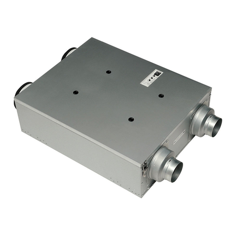
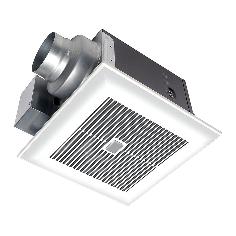
This product is listed by UL under UL file No.
E78414. This product use a sirocco fan driven
by a DC motor powered by an integral transformer.
The motor is designed to have long operating life,
high dynamic response, higher speed ranges and
energy savings. The grille covering the fan body is
a spring-attached, quick removal type. A damper
for preventing air counter flow is provided. The
blower uses a high-capacity sirocco fan developed
to reduce the noise level. The lightning unit is an
energy-saving LED lightning device that uses one
10 W LED lamp and produces almost the same
illumination as a standard 40 W incandescent lamp.
Night light feature consumes around 0.1 to 0.4 W.
TYPE IC-INHERENTLY PROTECTED.
3
GUIDE INSTALLATION / GUÍA DE INSTALACIONES
Floor /
Piso.
45°
45°
Fig. A
(Cooking area) Do not install above or inside this area /
(Área de cocina) No instale sobre esta área ni en su interior.
Bend close to duct adaptor / Curva
próxima al adaptador del ducto.
Squeezed duct /
Ducto comprimido.
Successive bending /
Doblado sucesivo.
Excessive bending /
Doblado excesivo.
No instale el ventilador encima o dentro de un ángulo de
45 grados proyectado hacia afuera desde el elemento del
equipo de cocina más cercano al ventilador (Fig. A).
Do not install fan above or inside a 45-degree angle
projected outwards from the cooking equipment
element closest to the fan (Fig. A).
4-inch roof jack, wall cap, or soffit vent with back-draft damper. /
Extractor de techo de 4 pulgadas, cubre muros
o rejilla de ventilación Soffit con amortiguador
de contracorriente.
2-3 ft straight run before elbow. /
Tramo recto de 2-3 pies antes del codo.
Short piece of flexible duct helps alignment
and absorbs sound.* /
Un tramo corto de ducto flexible ayuda a
alineación y absorbe
el sonido.*
Insulation /
Insulación.
Foil tape tightly covers all metal
duct joints.* /
El encintado metálico cubre
firmemente todas las uniones de
los ductos metalicos.*
3. A circular 4 inch duct is recommended for best
performance and proper fan installation.
Mechanically connect duct
to termination and seal with
mastic or approved foil faced
tape.* /
Conecte mecánicamente el
ducto a la terminación y
séllelo con masilla o cinta de
aluminio aprobada.*
In attic installation, caulk box to
drywall.* /
En instalación de áticos, selle la caja
metálica en el techo*.
*Seal with mastic or approved
foil faced tape /
*Selle con masilla o cinta de
aluminio aprobada.
SP
EN
Cooking equipment /
Equipo de cocina.
3. Un ducto circular de 4 pulgadas es recomendado para el
mejor rendimiento y una instalación adecuada.
1. Do not install the unit where ducts are configured
as shown below.
1. No instale la unidad cuando los ductos están
configurados como se muestra enseguida.
2. “The ducting has a strong effect on the air flow,
noise and energy use of the fan. Use the shortest,
straightest duct routing possible for best
performance, and avoid installing the fan with
smaller ducts than recommended. Insulation around
the ducts can reduce energy loss and inhibit mold
growth. Fans installed with existing ducts may not
achieve their rated airflow.”
2. ”Los ductos tienen un fuerte efecto en el flujo de aire,
ruido y energía usada por el ventilador. Use la ruta más
corta de ductos para el mejor rendimiento y así evitar la
instalación de ductos más pequeños de lo recomendado.
El aislante alrededor de los conductos puede reducir la
pérdida de energía e inhibir el crecimiento de moho. Los
ventiladores instalados con ductos existentes pueden no
lograr su flujo de aire nominal.”
4. Ensure duct joints and exterior penetrations are
sealed with caulk or other similar material to create
an air-tight path and to minimize building heat loss
and gain and reduce the potential for condensation.
4. Asegúrese de que las uniones de los conductos y los
orificios exteriores sean sellados con masilla u otro material
similar para crear un espacio hermético para minimizar la
perdida de calor y reducir el potencial de condensación.
5. Place/wrap insulation around duct and/or fan to in
order to minimize possible condensation buildup
within the duct, as well as minimize building heat loss
and gain.
5. Ponga/envuelva material para insulación alrededor del
ducto o ventilador para así minimizar la posible generación
de condensación, así como también minimizar el aumento
y perdida de calor.
