manuals.online logo
Brands
  1. Home
  2. •
  3. Brands
  4. •
  5. Panasonic
  6. •
  7. Security Sensor
  8. •
  9. Panasonic GP-X SERIES User manual

Panasonic GP-X SERIES User manual

Connection
Environment
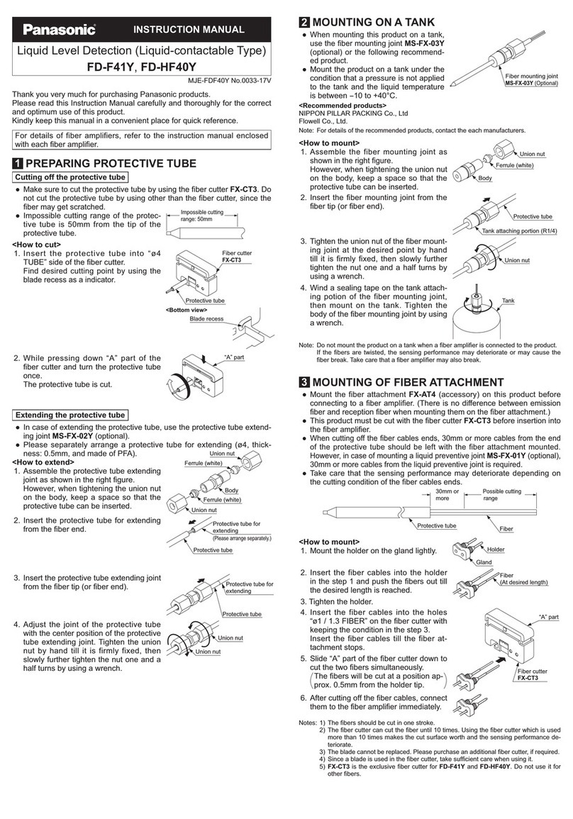
1) Where measurement conditions have not been specified precisely, the conditions used were an
ambient temperature of +20°C.
2) This value was obtained at a constant +25°C.
3) The value is in the range from 20 to 60% of the maximum detection distance with a combination of
sensor head and controller.
4) When using the BCD output unit GP-XBCD, the analog voltage output of a controller becomes invalid.
5) Adjusted to a 0 and +5V factory setting.
Notes:
Power Supply
Wiring
Compatibility
D
C
Metal
ەDistance from surrounding metal
As metal around the sensor may affect the detection,
take care of the following.
<Embedding of the sensor in metal>
Measurement value or analogue voltage output may be
changed if the sensor is completely embedded in metal.
Keep the minimum distance specified in the table below.
If sensor heads are mounted close
together without using the interference
prevention function, reserve the distance
specified below.
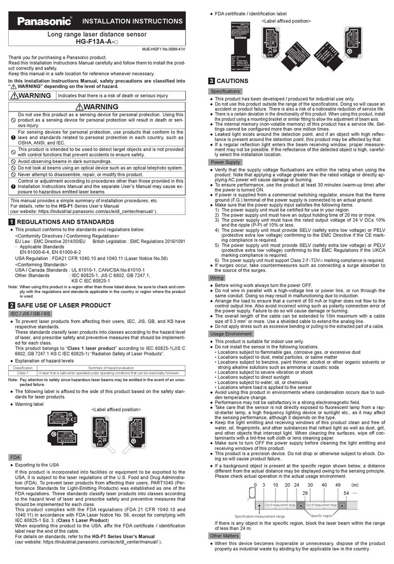
Thank you for purchasing our product. Be sure to read this manual before use in order to
ensure the safe and proper operation of this product. Keep this manual at hand for your
reference after reading it through. For details, refer to the GP-X Series User's Manual to make
settings for use. For the new info of the product and new version of the user’s manual, please
check our website (https://panasonic.net/id/pidsx/global).
This product is to inspect (discriminate/measure) sensing objects. Never use
this product for prevention of accidents which damage a human life or
properties or for safety maintenance.
WARNING
Check the following items before using this product.
zController Type(Product Name)
Check the model number on the top of the controller.
zBundled Items
Make sure that the following items are in the package.
• Controller × 1 㺃Mounting frame× 1㺃Sensor head × 1
• Hexagonal nut × 2 (For GP-X10M, GP-X12ML and GP-X22KL only)
• Toothed washer × 1 (For GP-X10M, GP-X12ML and GP-X22KL only)ࠉ
• Instruction Manual (This publication) × 1
Getting Started
Mounting Method
3
Short-circuit
protection
Comparison output
Alarm output
Strobe output
0.075ms (Fastest)
0.02% F.S. (64 times average processing)
0.04% F.S. (64 times average)
Within 0.3% F.S.
Response time
Temperature
characteristic
(Note 3)
Linearity (Note 2)
Resolution (Note 2)
Output voltage: 5 to 5V (Note 5)
Output impedance: 100 approx.
150mA or less
PNP output
24V DC 10% Ripple P-P 10% or less
Supply voltage
Current consumption
Analog voltage output
NPN output
Set model No.
Item
5 digit green LED
(display of numerical values within the upper and lower limit value)
5 digit orange LED (display of numerical values out of the upper and lower limit value)
Upper line digital indicator part
Lower line digital indicator part
Indicator
Orange LED (lights up in mode status)
Orange LED (lights up when the upper value is exceeded)
Green LED (lights up when within the upper and lower limit value)
MODE
HI
GO
Green LED (lights up as per the external or internal trigger timing)
TIMINIG
Push button setting/External input setting
40kHz (25 s)
Sampling frequency
Zero-set setting method
External input
Incorporated
Orange LED (lights up when less than the lower limit value)
LO
<PNP output type>
Photo coupler input
Input current: 9mA or less
Operating voltage: ON voltage 17V or more
(between 0V and input)
OFF voltage 4V or less
(between 0V and input)
Input impedance: 5k approx.
<NPN output type>
Photo coupler input
Input current: 9mA or less
Operating voltage: ON voltage 17V or more
(between 24V and input)
OFF voltage 4V or less
(between 24V and input)
Input impedance: 5k approx.
<NPN output type>
NPN open-collector transistor
Maximum sink current: 100mA
Applied voltage: 30V DC or less
(between output and 0V)
Residual voltage: 1.6V or less
(at 100mA sink current)
0.4V (at 16mA sink current)
<PNP output type>
PNP open-collector transistor
Maximum source current: 100mA
Applied voltage: 30V DC or less
(between output and V)
Residual voltage: 1.6V or less
(at 100mA source current)
0.4V (at 16mA source current)
0.07% / F.S./°C or less
࣭The GP-X series is configured to satisfy the specification with the combination of the sensor head
and the controller. Use the sensor head and controller in combination without fail; with other
combinations, not only may the specifications may not be satisfied but also failure may result.
࣭Turn the controller off before mounting or removing the sensor head and controller.
࣭Note that the cables will be damaged if they are pulled.
࣭Wait 15 minutes (or 20 minutes with GP-X3S and GP-X5S) after the power is turned on before
operation is started. There may be a variation in the measurements immediately after power-on
because the power circuit is not stable.
࣭There is a muting time of about two seconds after the power is turned on.
࣭Take care that wrong wiring may damage the sensor.
࣭Verify that the supply voltage variation is within the rating.
࣭If power is supplied from a commercial switching regulator, ensure that the frame ground (F.G.)
terminal of the power supply is connected to an actual ground.
࣭Make sure to use an isolation transformer for the DC power supply. If an auto-transformer
(single winding transformer) is used, this product or the power supply may get damaged.
࣭In case a surge is generated in the used power supply, connect a surge absorber to the supply
and absorb the surge.
࣭Do not run the wires together with high-voltage lines or power lines or put them in the same
raceway. This can cause malfunction due to induction.
࣭Make sure that the power supply is off while wiring.
࣭The analog voltage output is incorporated with a short circuit protection circuit. Do not connect
it directly to a power supply or a capacitive load.
࣭Be careful to avoid statically charging connectors during wiring work. A failure may result.
࣭Use the exclusive extension cable for cable extension of the sensor head.(Overall length: 10m)
࣭This product has been developed / produced for industrial use only.
࣭Avoid dust, dirt, and steam.
࣭Take care that the sensor does not come in direct contact with water, oil, grease, or organic
solvents, such as, thinner, etc.
࣭In case noise generating equipment (switching regulator, inverter motor, etc.) is used in the vicinity
of this product, connect the frame ground (F.G.) terminal of the equipment to an actual ground.
࣭Take care that stress is not directly applied to the cable joint.
࣭This sensor is for indoor use only.
࣭In case the sensor head is broken, the sensor head replacement is possible with same model.
(However, entering a characteristics code (ID code) and calibration are required)
GP-X3SE
GP-X5SE
GP-X8S
GP-X10M
GP-X12ML
GP-X22KL
18
14 or more
20 or more
50
50
Model D(mm)C(mm)
10
14
3 or more
Notes : 1)
2)
In case of without a nut. If a nut is fitted,
this value will be 23.5mm or more.
Mount such that the nuts do not protrude
from the thread portion.
GP-X10M
GP-X12ML
9.8N㺃m or less
20N㺃m or less
Model
7 or more
14 or more
GP-X22KL
20N㺃m or less
20 or more (Note 1)
Tightening torque
B(mm)
Note: Avoid tightening excessively.
GP-X3SE
GP-X5SE
GP-X8S
0.1N㺃m or lessࠉ
0.58N㺃m or lessࠉ
0.44N㺃m or lessࠉ
Model
4 to 16
Tightening torque
A(mm)
5 to 16
GP-X10M GP-X12ML
Attached
toothed lock
washer
Mounting
plate
BB
Attached
toothed lock
washer
Mounting
plate
Attached
toothed lock
washer
Mounting
plate
GP-X22KL
B
A
Set screw (M3 or smaller)
(Cup point)
A
In the case of an opposing installation layout
B
In the case of a parallel installation layout
Tighten the sensor head to the torque specified below.
ەMounting with set screw
ࠉ<Column type>
ࠉUse an M3, or less, cup-point set screw.
ەMounting with nut
ࠉ<Screw type>
Precautions
2
ەIn case the interference prevention
function is not used
Main Specifications
1
1) Where measurement conditions have not been specified precisely, the conditions used were
an ambient temperature of +20 ḥ.
2) The sensing range is specified for the standard sensing object.
3) The value represents 20 to 60% of the maximum sensing distance when combining the sensor
head and controller.
4) For the flexible cable type, please contact our office.
5) The given weight of the threaded type sensor head is value including the weight of the nut and
toothed lock washer.
6) If using the sensor in an environment where cutting oil droplets splatter, the sensor may be
deteriorated due to added substances in the oil. Please check the resistivity of the sensor against
the cutting oil you are using beforehand.
Notes:
Material
Power supply line: 1,000Vp, 10ms cycle, 0.5 s pulse width
Radiation: 300Vp, 10ms cycle, 0.5 s pulse width (with noise simulator)
Noise immunity
ATA4811 (Controller mounting bracket): 1 set
Accessory
Enclosure: Polycarbonate
Floating earth
Grounding method
120g approx.
Weight
35 to 85%RH, Storage: 35 to 85%RH
10 to 55Hz frequency, 0.75mm amplitude in X, Y and Z directions for two hours each
100m/s2 acceleration (10G approx.) in X, Y and Z directions five times each
Ambient
temperature
Ambient
humidity
Vibration resistance
Shock resistance
Environmental resistance
NPN output
Set model No.
Item
PNP output
zContoroller
GP-XC22KL-P
GP-XC3SE-P GP-XC5SE-P
GP-XC3SE GP-XC5SE
GP-XC8S-P GP-XC10M-P GP-XC12ML-P
GP-XC8S
GP-XC10M GP-XC12ML GP-XC22KL
zSensor head
80g approx.
45g approx.50g approx.40g approx.
40g approx.40g approx.Weight (Note 5)
Connector attached high frequency coaxial cable, 3m long
(Note 4)
Extension up to 10m is possible with the optional cable
PP
㸫
Cable protector
PAABSPARABS
Sensing surface
Brass (Nickel plated)Stainless steel (SUS303)
0 to 10mm
0 to 5mm
0 to 2mm0 to 1mm0 to 0.8mm
Stainless steel (SUS304)/ Iron sheet [Cold rolled carbon steel (SPCC)] 60 x 60 x t 1 mm
0.07%F .S ./ḥor less
IP67 (IEC) , IP67G (Note6)
-10 to +55 ḥ, Storage: -20 to +70 ḥ
35 to 85% RH, Storage: 35 to 85% RH
GP-X22KL
ȭ22mm
GP-X12ML
M12 type
GP-X10M
M10 type
GP-X8S
ȭ8mm
GP-X3SE GP-X5SE
Item
Typ e
Mater ial
Cable
Cable extension
Enclosure
Temperature
characteristics(Note 3)
Protection
Ambient temperature
Ambient humidity
Sensing range (Note 2)
Standard sensing object
250V AC for one min. between all supply terminals connected together and enclosure
Voltage withstandability
Power line: 300Vp 10ms cycle,and 0.5 s pulse width (with noise simulator)
20M ,or more, with 250V DC megger between all supply terminals connected together and enclosure
10 to 150 Hz frequency, 0.75mm amplitude, in X, Y and Z directions for two hours each
500m/s2acceleration (50G approx.) in X, Y and Z directions for five times each
Noise immunity
Insulation resistance
Vibration resistance
Shock resistance
ȭ5.4mm type
ȭ3.8mm type
Model No.
(Note4)
0 to+50°C (No dew condensation), Storage: 0 to+50°C
GP-XC3SE GP-XC5SE
GP-XC22KL-P
GP-XC3SE-P GP-XC5SE-P GP-XC8S-P GP-XC10M-P GP-XC12ML-P
GP-XC8S
GP-XC10M GP-XC12ML GP-XC22KL
MJE-GPXC No.0082-92V
GP-X Series
INSTRUCTION MANUAL
High-Speed,High-Accuracy Eddy Current
Digital Displacement Sensor
GP-X22KL 200 200
GP-X3SE
GP-X5SE
GP-X8S
GP-X10M
GP-X12ML
Model no. of
sensor head AmmBmm
15 9
30 11
40 15
40 15
170 50
NPN Type(GP-XCڧS,GP-XCڧMڧ,GP-XCڧKL)
PNP Type(GP-XCڧS-P,GP-XCڧMڧ-P,GP-XCڧKL-P)
Parts name and functions
4
I/O Circuit
6
Operation System
5
With a signal sent from another
controller, effects caused by
interference are removed.
Common
Measurement begins.
Temporarily finishes the
holding interval.
Supply power.
One among four settings is
called up from the internal
memory to replace the current
setting with it.
The measurement is output in
an analog voltage.
The current detection position is
forcibly zeroed (to become a
reference position).
A signal is output if an error
occurs.
An internal trigger outputs for
measurement interval.
A signal is sent to another controller
for removal of effects caused by
interference.
Common
A signal is output if the
measurement is between the
upper and lower limit values.
A signal is issued if the
measurement is larger than the
upper limit value.
A signal is output if the
measurement is smaller than
the lower limit value.
LO output
GO output
HI output
Common
Alarm output
Strobe output
Interference
prevention
output
Analog ground
Analog voltage
output
Zero setting
input
Memory
switch 1
Memory
switch 2
Common
Timing input
Reset
input
Interference
prevention
input
Power
supply 0V
Power supply
24V DC
LO
GO
HI
COM
ALARM
STROBE
INT P OUT
0 SET
GND
OUT
1
2
COM
TIMING
RESET
INT P IN
0V
24V DC
ANA
LOG
MEM
ORY
1
2
3
4
5
6
7
8
9
10
11
12
13
14
15
16
17
18
Indication
Terminal
No.
Name Description
Output
Input
Power
supply
Analog
output
NPN output type: 0V
PNP output type: 24V
NPN output type: 0V
PNP output type: 24V
Starts the setting mode.
Returns to the original state in
the setting mode.
Use these keys to select the
setting value and setting items.
Determines the setting item and
setting value.
Moves among setting digits.
The measurement, calculated
value, setting data and so on are
displayed.
The measurement is displayed in
green on the lower line with the
GO judgment, while it is
displayed in orange on the upper
line with the HI or LO judgment.
Lights up if the measurement is
larger the upper limit value.
Lights up if the measurement is
between the upper and lower
limit values.
Lights up if the measurement is
smaller than the lower limit
value.
Lights up at the timing of an
external or internal trigger.
Lights up in the setting mode,
while it is not lit during
measurement.
Resets the controller forcibly to
zero (reference position) with the
current detection position to shift
the display and analog voltage
output.
Digital
display
(green,
orange)
HI
indicator
(Orange)
GO
indicator
(Green)
LO
indicator
(Orange)
TIMING
indicator
(Green)
MODE
indicator
(Orange)
MODE key
DOWN key
UP key
ENTER key
0-set key
SHIFT key
1
2
3
4
5
6
7
8
9
10
11
12
No.Description Function
*1
or
Non-voltage contact or
PNP open-collector transistor
Zero setting input,
memory switch input 1/2
Reset input
Low (0V or open): Invalid
High ( 17 to 24V): Valid
*2
PNP open-collector transistor
Timing input
Low (0V or open): Invalid
High ( 17 to 24V): Valid
Low: 0V or open, High: 17 to 24V
Load
Load
Load
Load
Load
Users' circuitInternal circuit
D1
Terminal No.
24V DC
10%
T
r1
ZD1
4747
Comparison output LO
18
Comparison output GO
Output common
4
Comparison output HI
1
Strobe output
2
Alarm output
Interference
prevention output
3
V
0V
7
9
17
Analog ground
8
10
11
12
14
15
Input common ( 24V)
Reset input
Timing input
Memory switch input 2 (Note 2)
Memory switch input 1
(Note 2)
Zero setting input
Interference prevention input
Tr2ZD2
Tr3ZD3
Tr4
ZD4
Tr5ZD5
ZD6
Tr6
100mA max.
100mA max.
100mA max.
100mA max.
100mA max.
*1*1 *1 *2 *1
5
6
16
13
5k
5k
5k
5k
5k
5k
Analog voltage output: 5 to 5V (Note 1)
Main circuit
Memory switching input (Note 2)
Memory switch 2
Low
Low
High
High
Memory switch 1
Low
High
Low
High
Memory No.
0
1
2
3
Devices connected to the
analog voltage output
(terminal No. and ) must
have 1M or larger input
impedance.
To perform memory switching
by means of an external
terminal, select "Ext" as the
memory switching method.
For details, refer to section
"4.8 Memory Switching
Method Setting".
Notes: 1)
2)
Symbol...D1, D2
ZD1 to ZD6
Tr1to Tr6
:
:
:
Reverse supply polarity
protection diode
Surge absorption zener diode
PNP output transistor
*1
Non-voltage contact or
NPN open-collector transistor
or
Zero setting input,
memory switch input 1/2
Reset input
Low (0 to 4V): Valid
High ( V or open): Invalid
*2
NPN open-collector transistor
Timing input
Low (0 to 4V): Valid
High ( V or open): Invalid
Symbol...D1, D2
ZD1 to ZD6
Tr1to Tr6
:
:
:
Reverse supply polarity
protection diode
Surge absorption zener diode
NPN output transistor
Memory switching input (Note 2)
Low: 0 to 4V, High: V or open
Memory switch 2
High
High
Low
Low
Memory switch 1
High
Low
High
Low
Memory No.
0
1
2
3
Devices connected to the
analog voltage output
(terminal No. and ) must
have 1M or larger input
impedance.
To perform memory switching
by means of an external
terminal, select "Ext" as the
memory switching method.
For details, refer to section
"4.8 Memory Switching
Method Setting" .
Notes: 1)
2)
TIMING
MODE ENTER
LO GO HI
set
1
78911
2
3
4
6
10
12
5
Correction coefficient table
0.5 approx.
1
Sensor head
Stainless steel (SUS304), iron
Metal
Aluminum
Set 1
RS-232C
communication setting
BCD output unit setting
Controller communication
unit setting and address
setting
Controller communication
unit setting calculation
setting
Setting upon replacement
of sensor head
Software version display
Option
Indication varies according to the
mode selected in the application
mode. The figure on the left
indicates what is displayed with the
selection of the manual mode.
*
Display/confirmation Setting mode
Detection state
Upper limit value
Lower limit value
Application mode
Averaging
frequency
Memory number selection
Upper limit value
Lower limit value
Application mode
Averaging frequency
Select the object to
be detected
Calibration
Display scale
Analog voltage
output scale
Display setting
Interference
prevention setting
Memory switching
method setting
Initialization to factory
shipment settings
Judgment output setting
ەSensing range
The sensing range is specified for the standard
sensing object (Stainless steel/iron).
With a metal other than the metals specified in
the specifications, multiply with the correction
coefficient shown in the table below.Check the
effect with the actual machine.
D1
Terminal No.
100mA
max.
Users' circuitInternal circuit
24V DC
10%
Tr1
100mA max.
ZD1
+
-
4747
Comparison
output LO
18
Comparison output GO
Output common
1
Comparison output HI
2
Load
Load
Load
Load
Load
Strobe output
3
Alarm output
Interference prevention output
5
V
4
Analog voltage output: 5 to 5V (Note 1)
9
17
Analog ground
10
11
12
14
15
Input common
(0V)
Reset input
Timing input
Memory switch input 2 (Note 2)
Memory switch input 1 (Note 2)
Zero setting input
Interference
prevention input
Tr2
ZD2
Tr3
ZD3
Tr4
ZD4
Tr5
ZD5
ZD6
Tr6
100mA max.
100mA max.
100mA max.
*1 *2 *1*1 *1
6
7
24V
5k
24V
24V
24V
24V
24V
5k
5k
5k
5k
5k 16
13
0V
Main circuit
8
123456789
10 11 12 13 14 15 16 17 18
Sensor head connection
connector Sensor cable length
selection switch
RS-232C connector
Terminal block
ەExternal I/O
Operating Conditions for Compliance with CE
Marking / UKCA Marking
ەOperation Panel
࣭The controller must be connected within 10m of the power supply.
࣭The Signal cable connected to the controller must be shorter than 30m.
࣭A ferrite clamp must be mounted within 10mm of the base of the single connector of the
ࠉcable (GP-XBCC3) for the BCD output unit.
September, 2022 PRINTED IN JAPAN
Panasonic Industrial Devices SUNX Co., Ltd. 2022
Panasonic Industry Co., Ltd.
Panasonic Industrial Devices SUNX Co., Ltd.
https://panasonic.net/id/pidsx/global
Please visit our website for inquiries and about our sales network.
When using as a product in conformity with EMC Directive (2014/30/EU) /
EMC Regulation (2016/1091), observe the following requirements and conditions.
7
GP-X3SEࠊGP-X5SE
GP-X8SࠊGP-X10M
GP-X12MLࠊGP-X22KL

Other manuals for GP-X SERIES

3

This manual suits for next models

18

Other Panasonic Security Sensor manuals

Panasonic KX-TGA20 User manual

Panasonic

Panasonic KX-TGA20 User manual

Panasonic SF4B-F31G(V2) User manual

Panasonic

Panasonic SF4B-F31G(V2) User manual

Panasonic SF4B-H G-01 Series User manual

Panasonic

Panasonic SF4B-H G-01 Series User manual

Panasonic EKL3105 User manual

Panasonic

Panasonic EKL3105 User manual

Panasonic HG-S Series User manual

Panasonic

Panasonic HG-S Series User manual

Panasonic SF4-AH Series User manual

Panasonic

Panasonic SF4-AH Series User manual

Panasonic HG-C Series User manual

Panasonic

Panasonic HG-C Series User manual

Panasonic HG-F13A-A-N User manual

Panasonic

Panasonic HG-F13A-A-N User manual

Panasonic SF4D-*-01 Series User manual

Panasonic

Panasonic SF4D-*-01 Series User manual

Panasonic HG-S Series User manual

Panasonic

Panasonic HG-S Series User manual

Panasonic SF4B V2 series User manual

Panasonic

Panasonic SF4B V2 series User manual

Panasonic HG-T1010 User manual

Panasonic

Panasonic HG-T1010 User manual

Panasonic GD-3 User manual

Panasonic

Panasonic GD-3 User manual

Panasonic SF4B V2 series User manual

Panasonic

Panasonic SF4B V2 series User manual

Panasonic SE4D Series User manual

Panasonic

Panasonic SE4D Series User manual

Panasonic EQ-30 Series User manual

Panasonic

Panasonic EQ-30 Series User manual

Panasonic CX-44 Series User manual

Panasonic

Panasonic CX-44 Series User manual

Panasonic ST4 Series User manual

Panasonic

Panasonic ST4 Series User manual

Panasonic HG-T1110 User manual

Panasonic

Panasonic HG-T1110 User manual

Panasonic KX-HNS104EX User manual

Panasonic

Panasonic KX-HNS104EX User manual

Panasonic BM-ET330E User guide

Panasonic

Panasonic BM-ET330E User guide

Panasonic WRT 3374K-8 User manual

Panasonic

Panasonic WRT 3374K-8 User manual

Panasonic HL-G1 Series User manual

Panasonic

Panasonic HL-G1 Series User manual

Panasonic Firetracker FT128 User manual

Panasonic

Panasonic Firetracker FT128 User manual

Popular Security Sensor manuals by other brands

Larson Electronics MS-AT-7A-LV instruction manual

Larson Electronics

Larson Electronics MS-AT-7A-LV instruction manual

Sensit HXG-3P instruction manual

Sensit

Sensit HXG-3P instruction manual

STEINEL PROFESSIONAL IR 180 COM1 Information

STEINEL PROFESSIONAL

STEINEL PROFESSIONAL IR 180 COM1 Information

System Sensor B210LP Installation and maintenance instructions

System Sensor

System Sensor B210LP Installation and maintenance instructions

Security-Center FU5125 installation guide

Security-Center

Security-Center FU5125 installation guide

AJAX FireProtect user manual

AJAX

AJAX FireProtect user manual

urmet domus 1051 quick guide

urmet domus

urmet domus 1051 quick guide

Bosch TriTech+ Professional ISC-PDL1-WAC30G installation instructions

Bosch

Bosch TriTech+ Professional ISC-PDL1-WAC30G installation instructions

PNI SafeHouse HS140 user manual

PNI

PNI SafeHouse HS140 user manual

Oceanic Systems 5302 installation instructions

Oceanic Systems

Oceanic Systems 5302 installation instructions

Teknim TFD-1271 Installation & user manual

Teknim

Teknim TFD-1271 Installation & user manual

Major tech MS361 instruction manual

Major tech

Major tech MS361 instruction manual

EnOcean EDK 350 user manual

EnOcean

EnOcean EDK 350 user manual

Dectris EIGER2 X 500K Technical specifications

Dectris

Dectris EIGER2 X 500K Technical specifications

Visonic K-980 installation instructions

Visonic

Visonic K-980 installation instructions

Forch 5380 16 1 manual

Forch

Forch 5380 16 1 manual

Distech Controls GS-AQOPM Series installation guide

Distech Controls

Distech Controls GS-AQOPM Series installation guide

Lithonia Lighting LVS Series Installation instruction supplement

Lithonia Lighting

Lithonia Lighting LVS Series Installation instruction supplement

manuals.online logo
manuals.online logoBrands
  • About & Mission
  • Contact us
  • Privacy Policy
  • Terms and Conditions

Copyright 2025 Manuals.Online. All Rights Reserved.