PANCONTROL PAN MV-690A User manual

English
1
MANUAL
PAN MV-690A / PAN MV-690B

English
2
Manual
PAN MV-690A / MV-690B
Voltage tester with LED Display / LCD Display
Contents
1. Introduction............................................................................................3
2. Scope of delivery ....................................................................................3
3. Safety Instructions ..................................................................................4
4. Symbols Description ...............................................................................5
5. Panel Description....................................................................................6
6. General Specifications ............................................................................9
7. Operating Instructions ..........................................................................11
8. Maintenance.........................................................................................14
9. Guarantee and Spare Parts ...................................................................15

English
3
1. Introduction
Thank you for purchasing PANCONTROL. Since 1986, the PANCONTROL brand
has stood for practical, innovative and professional measuring instruments.
We hope you enjoy using your new product and we are convinced that it will
serve you well for many years to come.
Please read this operating manual carefully before using the device to become
familiar with the proper handling of the device and to prevent faulty
operations. Please follow all the safety instructions. Nonobservance cannot
only result in damages to the device but in the worst case can also be harmful
to health.
2. Scope of delivery
After unpacking please check the package contents for transport damage and
completeness.
•Measurement device with Handset
•Probes 4mm (for screwing on)
•Operating manual

English
4
3. Safety Instructions
To ensure the safe use of the device, please follow all the safety and
operating instructions given in this manual.
-Before using the device, make sure that it is intact and is functioning
properly.
-The device must no longer be used if the housing is damaged, if one or more
functions fail if no function is displayed, or if you suspect that something is
not right.
-If the safety of the user cannot be guaranteed, the device may not be
operated and secured against use.
-Touch the measuring instrument and handpiece only on the handles behind
the finger guard.Do not touch the test probes!
-Never allow the appliance to be plugged into an outlet without holding it,
otherwise it may be damaged.
-Never ground yourself while making electrical measurements. Do not touch
any exposed metal pipes, fittings etc., which could have a ground potential.
Ensure that your body is isolated by using dry clothes, rubber shoes, rubber
mats or other approved insulation materials.
-Do not use the device in any higher category than allowed.
-Never connect the device to voltage or current sources that exceed the
specified maximum values.
-Do not use the device outdoors, in humid surroundings or in environments
that are subjected to extreme temperature fluctuations.
-Never use the device in an explosionprone environment.
-Do not store the device in places which are exposed to direct sunlight.
-Remove the battery if the device is not used for a long time.
-If changes or modifications are made to the device, the operational safety
is no longer guaranteed and the warranty becomes void.
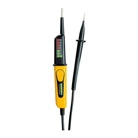
English
5
4. Symbols Description
Conforms to the relevant European Union directive (EN-61010)
Product is protected by double insulation
Risk of Danger. Important information See instruction manual
Attention! Hazardous voltage. Risk of electric shock.
This product should not be disposed along with normal domestic
waste at the end of its service life but should be handed over at a
collection point for recycling electrical and electronic devices.
CAT III
The device is designed for making measurements in building
installations. Examples are measurements on junction boards,
circuit breakers, wiring, switches, permanently installed sockets,
devices for industrial use as well as permanently installed motors.
(DC)
DC voltage / current (IEC 60417-5031)
(AC)
AC voltage / current (IEC 60417-5032)
Audible continuity tester

English
6
5. Panel Description
MV-690 A

English
7
MV-690 B

English
8
1
Probe Handset (–)
2
Probe Measurement device (+)
3
LED flashlight (Point Illumination)
4
LED Display (PAN MV-690 A)
LCD Display (PAN MV-690 B)
5
Indicator of the live phase
6
LED Voltage testing with reduced impedance
(only PAN MV-690A)
7
Rotating field counter-clockwise
8
Rotating field clockwise
9
Display Continuity test
10
Test button
(Testing of an residual current circuit breaker.)
11
Power button LED flashlight
12
Battery compartment
13
bargraph (only PAN MV-690B)

English
9
6. General Specifications
Display
PAN MV-690A: LED
PAN MV-690B: 3 ½ Digits LCD Display,
bargraph, Backlight
Rotary field indication
100 –400 V (50/60 Hz)
Category
CAT III 690 V
Overload protection
PAN MV-690A: 400 V (AC/DC) or 690 V (DC)
PAN MV-690B: 690 V (AC/DC)
Maximum value (MAX)
< 0,2 A (1s); < 3,5 mA (5s)
Test current
5 μA (Continuity test)
Internal impedance
≤1MΩ
Response time
< 0,1s
Measuring rate
2-3x /s
Max. uptime
to 230 V 5 s
to 690 V 3 s
Power consumption
250 mW
Power supply
2 x 1,5 V (AAA) Battery(s)
Operating temperatute
-10º C to 55º C / < 85% Relative Humidity
(%RH)
Altitude
max. 2.000 m
Weight
PAN MV-690A: 204 g
PAN MV-690B: 216 g
Dimensions
240 x 78 x 40mm

English
10
Function
Range
Accuracy of the value
displayed in %
DC voltage
(V =)
12 V
-30% to 0%
24 V
36 V
50 V
120 V
230 V
400 V
690 V
AC voltage
(V )
50/60Hz
12 V
-30% to 0%
24 V
36 V
50 V
120 V
230 V
400 V
690 V
only MV-690B

English
11
7. Operating Instructions
Be aware of the Safety Instructions.
Note: Before each measurement check the correct funktion at a known
power source.
Close the probes briefly. The "Audible continuity" (9) LED lights up and a
beep can be heard.
If the device does not respond during the function test replace the
battery.
DC Voltage measurement / AC Voltage measurement
Attention
Hazardous voltage! The probes may not be long enough to touch the hot
parts in some 230V wall sockets as they are deep inside. As a result, the
reading can show 0 volts. Make sure that the probes touch the metallic
contacts in the socket before assuming that voltage has not been applied.
Use the probes 4 mm.
1. Touch the measuring points with the probe tips.
(Measurement device +, Handset -)
2. The tester is activated at a voltage of 12V.
3. Once the reading stabilizes, read the value.
Note:For technical reasons, the MV-690A's 12 V LED only lights up when
both test buttons (10) are pressed!

English
12
DC Voltage measurement / AC Voltage measurement with
reduced impedance
For the voltage test with reduced impedance press both test buttons (10) during
the measurement. The impedance of about 7.7 kΩ is reduced, whereby
inductive and capacitive stray voltages are suppressed. With this function you
can choose between "real" difference voltages and stray voltages.
Single-pole phase test
Note: This measurement can only be performed when functional
batteries are inserted.
1. Touch a conductor with the device probe.
2. A beep indicates that the conductor is under voltage.
Testing of an residual current circuit breaker.
1. Touch probe with the outer conductor and the other probe to the ground
wire.
2. Press both test buttons in the middle of the voltage tester. This increases
the power consumption of the voltage tester at 230 V at 30 mA.
3. If the tested circuit is protected by a 30 mA RCD-breaker the circuit should
be switched off. If the If the RCD does not switch off, the switch is either
defective or the third prong (ground) of the plug is not in order.

English
13
Continuity test
Note: This measurement can only be performed when functional
batteries are inserted.
1. Connect the test prods of the leads to the resistance or circuit to be
tested. To avoid influence disconnect the resistant to be tested from the
circuit.
2. If there is a resistor < 35 Ω, you hear a beep. When the circuit is open, the
display shows "OL".
Rotation indicator of rotating fields
The tester can show the direction of the rotary field of three-phase.
The rotation indicator is always active and is displayed by the two LEDs.
1. Touch two phases of the 3-phase AC power source with the two probes of
the device.
2. If the "R" LED illuminates, the rotating field rotates clockwise - when the
"L" LED illuminates, the rotating field rotates counter-clockwise.

English
14
8. Maintenance
Only authorized service technicians may repair the instrument.
Note:
If the instrument is malfunctioning, please test:
- Battery condition and polarity
- Condition of the fuse(s) if available.
- Condition of the test leads.
Changing the battery(s)
If the device does not respond during the function test replace the battery.
Attention: Remove the probes from all voltage sources before opening the
device!
1. Open the battery compartment. (12)
2. Replace the battery. Mind the correct polarity.
3. Replace the battery compartment lid and secure the screw.
4. Disposal of the flat battery should meet environmental standards.
Cleaning
If the instrument is dirty after daily usage, it is advised to clean it by using a
humid cloth and a mild household detergent. Prior to cleaning, ensure that
instrument is switched off and disconnected from external voltage supply and
any other instruments connected. Never use acid detergents or dissolvent for
cleaning.

English
15
9. Guarantee and Spare Parts
This device is covered by the statutory warranty of 2 years after date of
purchase (according to purchase receipt).
Further information on complaint handling can be found at:
www.pancontrol.at/complaints
In case of spare part requirement or in case of queries
or problems, please get in touch with your vendor or:
Changes as a result of technical development,
as well as errors and printing errors reserved.
Vienna 02-2022
This manual suits for next models
1
Table of contents
Other PANCONTROL Test Equipment manuals

PANCONTROL
PANCONTROL PAN MAGNETFINDER User manual

PANCONTROL
PANCONTROL PAN LAN1 User manual

PANCONTROL
PANCONTROL PAN Volttester 400 User manual

PANCONTROL
PANCONTROL PAN VOLTFINDER User manual

PANCONTROL
PANCONTROL PAN 200A+ User manual

PANCONTROL
PANCONTROL PAN VOLTFINDER User manual

PANCONTROL
PANCONTROL PAN Volttester 400 User manual

PANCONTROL
PANCONTROL PAN Leitungssucher User manual

PANCONTROL
PANCONTROL PAN Stromkreisfinder User manual

PANCONTROL
PANCONTROL PAN VOLTFINDER User manual