Panduit SmartZone EPA126 User manual

Release 1.0
Issue 1.0
Remote Logger Unit
User Manual

Remote Logger Unit User Manual
-2-
Copyright © 2014 Panduit Corp. All rights reserved. No part of this book shall be reproduced, stored in a retrieval system, or transmitted
by any means, electronic, mechanical, photocopying, recording or otherwise, without written permission from Panduit. No patent liability
is assumed with respect to the use of the information contained herein.
Although every precaution has been taken in the preparation of this book, Panduit assumes no responsibility for errors or omissions.
Neither is any liability assumed for damages resulting from the use of the information contained herein.

Remote Logger Unit User Manual
-3-
Table of Contents
Remote Logger Unit 5
Environment Monitoring 5
PDU Monitoring 5
Contacting Panduit 5
Document Overview 6
Document History 6
Remote Logger Unit Package 7
Front of RLU 7
Rear of RLU 7
LEDs 7
Reset Button 8
Connections 8
Rack Mounting 9
Equipment Required 9
Before You Begin 9
Installation Warning Statements 9
Rack-Mount the RLU 10
Initial Setup 11
Installation Requirements 11
Connection to Configuration Interface 11
Default Network Settings 12
Initial Network Setup 12
Network Server Setup 12
Logging Setup 13
Power Meters 13
Configuration Records 13
UTL PDUs 14
Modbus Devices 15
Limits 15
Input Sensors 15
Probe Templates 16
Analog Probes 16
Digital Probes 16
Limits 17
Networked Configuration 17
Firmware Update 17
Serial Port 18
Networked 18
Bootloader 18
Troubleshooting 19
Resetting the RLU to Factory Default Settings 19

Remote Logger Unit User Manual
-5-
Remote Logger Unit
The Remote Logger Unit (RLU) is a compact device used to monitor multiple power
meters and multifunctional probe inputs.
The unit has both local and GPRS interfaces for monitoring and configuration.
The main features of the RLU include:
lMonitoring of up to eight power meters (UTL PDUs and ND Modbus) via four ports
lMonitoring of up to six multifunctional environment channels
lConfiguration and monitoring via local and network (GPRS) interfaces
lRS232 and USB interfaces for local access
lNetworked logging of monitor data
Environment Monitoring
The Remote Logger Unit has the capability to monitor temperature, humidity, air pres-
sure and speed, luminous intensity, contact state, and pulse count, and to raise alarms if
a user-configured threshold is crossed.
PDU Monitoring
The Remote Logger Unit via intelligent PDUs and ND Modbus meters allows around-
the-clock monitoring of the electrical power environment including the raising of alarms if
a user-configured threshold is crossed.
Contacting Panduit
For Technical Support on PIM Software, please contact Panduit Technical Support
using one of the following methods:
lToll-Free: 1-866-721-5302, Monday-Friday, 24 hours/day
l24/7 phone support - Response typically within the hour on weekends
lEmail: systemsupport@panduit.com

Remote Logger Unit User Manual
-6-
Document Overview
This manual uses the following typographic conventions:
{somevalue} Italics surrounded by curly braces indicate a user supplied
entry that must be input. E.g.: {drive}:\setup
<ctrl+alt+delete>
Text surrounded by angled brackets indicate specific keys to
be pressed. Use of the + sign in combination indicate that
keys should be pressed together.
Information of note may be presented like this.
Warning: These messages alert you to specific procedures or practices; serious con-
sequences, including injury, may result if you disregard them.
Document History
This manual is intended to document the Remote Logger Unit product.
Throughout this document it is assumed that the user has a basic to intermediate know-
ledge of IT and Networking concepts.Further information regarding IT and Networking
fundamentals may be found in the appendices of this document.
This is version 1.0 of this document.

Remote Logger Unit User Manual
-7-
Remote Logger Unit Package
The standard RLU package contains a Remote Logger Unit and a Localized Mains
Lead.
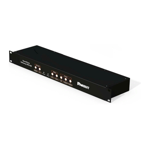
Front of RLU
The following image shows the front panel of the Remote Logger Unit:
Rear of RLU
The following image shows the rear panel of the Remote Logger Unit:
LEDs
LEDs can be found on the rear of the RLU. Their purpose is described below.
lPower:Illuminates when the unit is powered[Green LED]
lStatus:Indicates system activity[Yellow LED]
lRx/Tx:Indicates the network connection state[Yellow LED]
lModem:Indicates modem activity[Yellow LED]

Remote Logger Unit User Manual
-8-
Reset Button
The back of the RLU includes a Reset button, which allows the user to reboot the unit.
Connections
On the rear of the RLU are several connectors:
lPower Monitoring: PDUs connect here
lInputs: Probes are connected here
lSerial Port: For connection of a smart meter or serial terminal
lUSB: For connection of a USB device such as a serial terminal
lGSM: For connection of a GSM aerial

Remote Logger Unit User Manual
-9-
Rack Mounting
This section covers the basic bracket mounting of the RLU.
Equipment Required
You need to supply a minimum of two 5mm x 15mm pan head or hexagonal head bolts,
two 5mm washers and nuts, and the appropriate tools.
Before You Begin
When determining where to install the RLU, please verify that these guidelines are met:
lAirflow around the RLU is unrestricted.
lClearance to the front and rear panels meet these conditions:
lRear-panel LEDs can be easily read.
lAccess to ports is sufficient for unrestricted cabling.
lAC power cord from the power supply can reach the AC power outlet and the
RLU.
lThe aerial can be placed such that it has sufficient signal to make a con-
nection.Temperature around the RLU does not exceed 40oC.
lHumidity around the RLU does not exceed 90% Relative Humidity.
Installation Warning Statements
This section includes the basic warning statements.
lOnly trained and qualified personnel should be allowed to install, replace, or ser-
vice this equipment.
lTo prevent the RLU from overheating, do not operate in an area that exceeds the
maximum recommended ambient temperature of 40oC.
lInstallation of the RLU must comply with local and national electrical codes.
lThe rack or cabinet or fixing surface should be adequately secured to prevent it
from becoming unstable and/or falling over.
lTo prevent personal injury when mounting or servicing the RLU, you must take
care to ensure the system remains stable.
lCircuit Overloading - Consideration should be given to the connection of the equip-
ment to the supply circuit and the effect that overloading of circuits might have on
over current protection and supply wiring. Appropriate consideration of equipment
nameplate ratings should be used when addressing this concern.

Remote Logger Unit User Manual
-10 -
lReliable earthing of rack-mounted equipment should be maintained. Particular
attention should be given to supply connections other than direct connections to
the branch circuit (use of a power strip etc).
Rack-Mount the RLU
Hold the RLU and attach the bracket to the rack using two 12-24 screws.

Remote Logger Unit User Manual
-11 -
Initial Setup
Installation Requirements
lRemote Logger Unit.
lIEC mains lead (supplied localized).
lComputer system with serial terminal emulator program to set up the RLU.
lSerial lead (see below).
Connection to Configuration Interface
The Remote Logger Unit can be configured entirely using the command line interface
accessible via the RS232 and USB ports.
For the RS232 connection a lead will be needed as follows.
Function RLU Dir PC
RTS
6-way
RJ45
1 → 8
9-way D
female
Rx 2 ← 3
Gnd 3 ↔ 5
CTS 4 ← 7
Tx 5 → 2
3.3V 6 → -
For the USB connection a standard USB lead will be needed. The serial port terminal
should be configured as follows:
l115,200 bits/s
l8 bit
lNo parity
lNo flow control
When the USB connects a PC to an RLU for the first time, the drive will be installed. No
further setup is needed and the commands will work exactly as for the serial interface.

Remote Logger Unit User Manual
-12 -
Default Network Settings
To determine the default network settings enter the following at the CLI:
type autoapn
This will list the file containing all available network configurations. To determine
whether or not your network is configured you need to determine its IMSI and check
whether the first digits of this code appear as any of the network IDs (first field in each
data line) of the data returned.
Initial Network Setup
To discover the current configuration, enter:
CONFIG <filter>
where the filter is the first letters of a set of commands. CONFIG has two aliases: ? and
CFG.
If the ID of the required network isn’t present, the configuration can be entered manually
using the following commands:
GPRS_APN <apn_name>
GPRS_USERNAME <gprs_username>
GPRS_PASSWORD <gprs_password>
SAVE
To check these values enter:
CONFIG GPRS
Network Server Setup
To communicate with the network server for RLU configuration, data uploads, and firm-
ware updates, the server must be configured as follows:
SERVER_NAME 1 <server_1_name>|<server_1_ipaddr>
SERVER_PORT 1 <server_1_port>
SERVER_PASS 1 <server_1_password>
SAVE
To check these values enter:

Remote Logger Unit User Manual
-13 -
CONFIG SERVER
The server updates are configured as follows:
lUI <interval> sets the interval (in seconds) between successive server
update operations.
lUI_SYNC <time> sets a server update synchronization point (format: HHSS) in
the current 24-hour period.
lFW_NAME <fname> sets the name of a file (format: f or f_*) on the server in which
an application update image will be stored. This image will be downloaded and
installed if it differs from the currently installed image.
lSAVE saves the configuration.
Logging Setup
Prior to uploading to the power meter and probe monitoring information is periodically
stored on the RLU. The logging times are configured as follows:
lLI <interval> sets the interval (in seconds) between successive logging oper-
ations.
lLI_SYNC <time> sets a logging synchronization point (format: HHSS) in the cur-
rent 24-hour period.
lSAVE saves the configuration.
Power Meters
The power meter configuration is determined by a configuration record identified by the
ID number.
Configuration Records
The format of a configuration record is as follows:
<cfgrcd> = id>,<type>,<name>,<port>,<addr>,<baud>,<numslvs>
where
l<id> is an arbitrarily assigned unique number (1 through 8).
l<type> indicates the meter type ID as in table below.
l<name> is an arbitrarily assigned string of up to 31 characters.

Remote Logger Unit User Manual
-14 -
l<Port> is the physical port to which the meter is connected (1 through 4).
l<addr> is the base address of the meter if it is a Modbus device; otherwise the
value is set to 0.
l<baud> is the baud rate of the meter port.
l<numslvs> represents the number of slave units if relevant; otherwise this value
is set to 0.
ID Power Meter Type
0 None
1 UTL PDU Single-Phase
2 UTL PDU 48V DC
3 UTL PDU Three-Phase
4 ND Multi-Cube
5 ND 350
To read back a configuration record:
pwr cfg <id>
To install a new configuration record use:
pwr cfg <cfgrcd>
To delete a configuration record use:
pwr cfg <id+128>
To read back all configuration records use:
pwr cfg all
UTL PDUs
The types of PDU are:
lSingle-phase
l48V DC
lThree-phase
For these, <addr> and <numslvs> should both be 0.

Remote Logger Unit User Manual
-15 -
Modbus Devices
The types of digital sensors are:
lND MultiCube
lND 350
For ND 350 <numslvs> should be 0.
Limits
The thresholds that can be set are:
lkWh Upper Threshold
lkWh Lower Threshold
Limits may be configured as follows:
PWR ALARMSET <id>,<s1lt>,<s1ht>[;<snlt>,<pnht>]...
Values apply to all meter types. Slave channels must appear in address order.
Alarms are enabled by default when configured, but their enable status may be con-
trolled as follows:
PWR ALARMEN <id>,<s1le>,<s1he>[;<snle>,<snhe>]...
Alarm levels and the enable state for a particular meter can be read back as follows:
ENV ALARM <id>
Format for each row as follows:
Low: <threshold>(<en_state>) High: <threshold>(<en_state>)
Note: There are no lower limits for total energy as energy consumption can only go up
not down.
Input Sensors
The Input Sensor values are all determined by a template for its particular probe type.
Default templates are supplied for some probe types.

Remote Logger Unit User Manual
-16 -
Probe Templates
The format of a template is as follows:
<template> = <id>,<name>,<p0>,<p1>,...,<pn>
To read back the template for a particular probe id use:
env template <id>
To install a new template for a particular probe id use:
env template <template>
To uninstall a template and return to the default use:
env template <id>,0
To read back the names of all active templates use:
env template
Analog Probes
The types of analog sensors are:
lTemperature
lHumidity
lLuminous Intensity
lAir Pressure
lAir Velocity
For analog sensors, the template supplies a set of exactly 41 floating-point values (the
mapping), which define the output value over the full range of the sensor input, which
may be 0-5V or 0-10V, depending on probe type.
Digital Probes
The types of digital sensors are:
lOpen/Close Contacts
lPulse Count

Remote Logger Unit User Manual
-17 -
For digital sensors the template supplies a set of integer values defining open circuit
state and de-bounce counts (high and low) for each port. This set of values has the fol-
lowing format:
<o1>,<o2>,<o3>,<o4>,<o5>,<o6>,<h1>,<h2>,<h3>,<h4>,<h5>,<h6>,<l-
1>,<l2>,<l3>,<l4>,<l5>,<l6>
If an incomplete set of values is supplied, missing (trailing) values will be set to 0.
Limits
The thresholds than can be set are as follows:
lUpper Threshold
lLower Threshold
Limits may be configured as follows:
ENV ALARMSET <p1id>,<p1lt>,<p1ht>[;<pnid>,<pnlt>,<pnht>]...
Values apply to all probe types – including digital – regardless of measurement units.
Port configurations do not have to be in any particular order.
Alarms are enabled by default when configured, but their enable status may be con-
trolled as follows:
ENV ALARMEN <p1id>,<p1le>,<p1he>[;<pnid>,<pnle>,<pnhe>]...
Alarm levels and enable states can be read back as follows:
ENV ALARM
Format for each row:
Low: <threshold>(<en_state>) High: <threshold>(<en_state>)
Networked Configuration
All of the configuration commands described in this document may also be executed
from a server configuration file.
Firmware Update
There are two main ways of updating the application firmware: locally via a serial port
and remotely from the network server.

Remote Logger Unit User Manual
-18 -
Serial Port
To update firmware via the serial port, enter the following command at the terminal:
ymodem fw
Then use the Y Modem facility to send the application firmware update to the RLU. On
completion, restart the RLU by pressing Reset, and the new firmware version will install
and start to execute.
Networked
To update firmware via the network:
1. Rename the application firmware update file to be the same as for the FW_NAME
in the configuration parameters.
2. Copy the file to the server download/ directory. On the next server synchronization
the file will be downloaded and installed and the system restarted.
Note : The system will always attempt to update the firmware if it finds a valid update file
on the server that is different from the one currently being executed.
Bootloader
If the firmware cannot be updated via the application, then an update can be performed
by the bootloader.
1. Connect the PC to the RLU via the serial port and a terminal emulator program.
2. At the terminal emulator program, hold down the space bar and power the RLU.
The bootloader menu displays.
3. At the terminal, select option f, and then send the application image.
4. On completion of the download, select option tto install the update and start the
RLU (--- means deleting, +++ means programming).
5. On completion of firmware installation, select option jto start the RLU application.

Remote Logger Unit User Manual
-19 -
Troubleshooting
Resetting the RLU to Factory Default Settings
To reset the Remote Logger Unit to the factory default, perform the following steps:
Note: This process is best accomplished from the back side of unit (the side with the con-
nectors).
1. Press and release the Reset button. This starts the reboot process.
2. The green Status light will illuminate and then extinguish, and the red Alarm light
will illuminate. Press and hold the MODE button for around 10 seconds until the
Alarm light extinguishes.
3. Wait 30 seconds.
4. Press and release the Reset button to complete the process.
The factory default settings will be restored.

Remote Logger Unit User Manual
-20 -
Appendix A: Technical Details
Factory Default Settings
SmartZone EPA126 Gateway Defaults
IP Address 192.168.0.253
Subnet Mask 255.255.255.0 (/24)
Default Gateway 192.168.0.1
Web Management Address http://192.168.0.253/
Default Username admin
Default Password admin
Operating Information
Input Power 100-240 VAC (45W) 50-60 Hz
Operating Temperature 0OC to 40 OC
Storage Temperature -10 OC to 70 OC
Operating Humidity 5% to 90% RH
Storage Humidity 5% to 100% RH
Caution: There is a risk of explosion if the battery is replaced with and incorrect type.
Dispose of used batteries according to the instructions.
Other manuals for SmartZone EPA126
2
Table of contents
Other Panduit Gateway manuals

Panduit
Panduit Atlona AT-VGW-HW-20 User manual

Panduit
Panduit SmartZone EPA126 User manual

Panduit
Panduit SmartZone EP042 User manual

Panduit
Panduit SmartZone E24 User manual

Panduit
Panduit SmartZone EPA064 User manual

Panduit
Panduit ATLONA AT-VGW-HW-3 User manual
Panduit
Panduit Synapsense WSN User manual

Panduit
Panduit SynapSense 1167 Instructions for use

Panduit
Panduit SmartZone EPA126 User manual

Panduit
Panduit Synapsense User manual