manuals.online logo
Brands
  1. Home
  2. •
  3. Brands
  4. •
  5. Parker
  6. •
  7. Control Unit
  8. •
  9. Parker 2B4 Series User manual

Parker 2B4 Series User manual

AE High Pressure
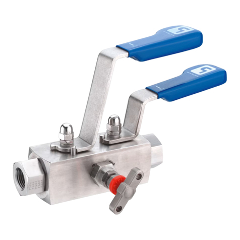
Ball Valve
Series 2B4
Operation and Maintenance Manual
Section 1.0
Description
The AE high pressure ball valve can be used at pres-
sure up to 20,000 psi (1380 bar) depending on the
tubing connections and operating temperatures.
The maximum operating media pressure at room
temperature is etched on the valve body. The curve
shown below can be used to nd the maximum
operating pressure at various media temperatures.
Section 2.0
Installation
The ball valve can be installed with the ow in
either direction.
Refer to the instruction section of the Autoclave
Engineers’ Valve, Fitting and Tubing Catalog for
proper tubing connection installation.
Refer to the manufacturer’s literature when
using air or electric operators.
Pressure/Temperature Curve
AUTOCLAVE ENGINEERS FLUID COMPONENTS RESERVES
THE RIGHT TO ALTER THE SPECIFICATIONS GIVEN IN THIS
PUBLICATION IN LINE WITH OUR POLICY OF CONTINUOUS
IMPROVEMENT.
ALL GENERAL TERMS AND CONDITIONS OF SALE,
INCLUDING LIMITATIONS OF OUR LIABILITY, APPLY TO ALL
PRODUCTS AND SERVICES SOLD.
STAINLESS STEEL HANDLE
STOPPING DEVICE
PACKING GLAND
LOCKING PIECE
SEAT GLAND
VITON O-RING
SEAT RETAINER
PEEK BEARING
LOCKNUT
SPRING ENERGIZED SEAL
THRUST WASHER
ONE PIECE BALL
AND STEM
CARBON FILLED
PEEK SEATS
20,000
(1380)
15,000
(1035)
10,000
(690)
5,000
(345)
00
(-18)
100
R.T. (38)
200
(93)
300
(150)
400
(204)
500
(260)
PRESSURE TEMPERATURE RATINGS
TEMPERATURE °F
(°C)
SF & F CONNECTION
NPT (1/8” & 1/2”) W125, SW250, SW375
SW 500 CONNECTIONS
PRESSURE IN PSIG
(BAR)
CAUTION: WHILE TESTING HAS SHOWN O-RINGS TO PROVIDE
SATISFACTORY SERVICE LIFE, BOTH CYCLIC AND SHELF LIFE
MAY VARY WIDELY WITH DIFFERING SERVICE CONDITIONS,
PROPERTIES OF REACTANTS, PRESSURE AND TEMPERATURE
CYCLING AND AGE OF THE O-RING. FREQUENT INSPECTION
SHOULD BE MADE TO DETECT ANY DETERIORATION AND
O-RINGS REPLACED AS REQUIRED.
02-0040ME July2013© 2013 Parker Hannin Corporation | Autoclave Engineers is a registered trademark of the Parker Hannin Corporation
Parker Hannin Manufacturing Ltd.
Instrumentation Products Division, Europe
Industrial Estate Whitemill
Wexford, Republic of Ireland
PH: 353 53 914 1566
FAX: 353 53 914 1582
Instrumentation Products Division
Autoclave Engineers Operation
8325 Hessinger Drive
Erie, Pennsylvania 16509-4679 USA
PH: 814-860-5700 FAX: 814-860-5811
www.autoclave.com
WARNING
FAILURE, IMPROPER SELECTION OR IMPROPER USE OF THE PRODUCTS AND/OR SYSTEMS DESCRIBED HEREIN OR RELATED ITEMS CAN CAUSE DEATH, PERSONAL INJURY AND PROPERTY DAMAGE.
This document and other information from Parker Hannin Corporation, its subsidiaries and authorized distributors provide product and/or system options for further investigation by users having technical
expertise. It is important that you analyze all aspects of your application and review the information concerning the product or system in the current product catalog. Due to the variety of operating conditions
and applications for these products or systems, the user, through its own analysis and testing, is solely responsible for making the nal selection of the products and systems and assuring that all performance,
safety and warning requirements of the application are met. The products described herein, including without limitation, product features, specications, designs, availability and pricing, are subject to change by
Parker Hannin Corporation and its subsidiaries at any time without notice.
Offer of Sale
The items described in this document are available for sale by Parker Hannin Corporation, its subsidiaries or its authorized distributors. Any sale contract entered by Parker will be governed by the provisions
stated in Parker's standard terms and conditions of sale (copy available upon request).
ISO-9001 Certied
Section 5.0
Assembly
General Assembly Procedure 1/4” Port 2-Way Ball
Valve
1. Drop bottom bearing into center opening of the body.
2. Using packing gland, delicately slide the stem seal and
backup onto the upper shoulder of stem. Lubricate seal and ball
surface with o-ring grease.
3. Lubricate the top of the upper shoulder of stem with Jet
Lube and slip the thrust washer onto the stem.
4. Lubricate the top of the thrust washer and packing gland
threads with Jet Lube and slip the packing gland onto the stem.
5. With the stem at to the left, screw the packing gland/stem
assembly into the body center opening until the opening of the
ball is aligned properly. Back packing gland out one complete
turn.
6. Assemble locknuts onto seat glands.
7. Install o-rings onto the seat glands and lube the o-rings
with grease.
8. Press seats into seat retainers and press these seat assem-
blies rmly onto the nose of the seat glands.
9. Lubricate seat gland threads with Jet Lube and insert seat
glands into body hand tight on both sides.
10. Keeping ball in full open position, pre-torque seat glands
to 150 in. lb. (17 Nm) in 25 in. lb. (2.8 Nm) alternating incre-
ments.
11. Back seat glands off on both sides and retorque to 75 in. lb.
(8.5 Nm) in 25 in. lb. (2.8 Nm) alternating increments.
12. While holding seat glands secure with a wrench, tighten
seat gland locknuts to the valve body.
13. Hand tighten packing gland.
14. Using a spanner wrench, tighten the locking piece to the
valve body.
15. Position stopping device loosely on top of packing gland
and attach the handle onto the at of the stem. Turn stopping
device clockwise until it hits the handle hub. Tighten the (2) set
screws on the stopping device onto the packing gland
.
Section 3.0
Precautions
Hold the seat glands with a wrench when tightening or
loosening the tubing connections.
DO NOT OPERATE THE VALVE WITH
MORE THAN 75 IN. LBS (8.5 Nm)
APPLIED TO THE SEAT GLANDS.
Ball valves can trap pressurized media inside the valve.
Relieve this pressure by turning the handle to the “half-
open” position before disassembling the valve.
Section 4.0
Maintenance
Routine maintenance consists of tightening the seat
glands periodically to compensate for seat wear. With no
pressure in the valve, use the
following procedures:
4.1 Seat Glands
4.1.1 Remove lock device from seat glands
4.1.2 While holding the seat glands and the body
secure, loosen the tubing connections
4.1.3 With the handle in the “Full Open ” position,
gradually tighten the glands alternating from one gland to
the other in increments of 25 in. lbs. (2.8 Nm) until 75 in.
lbs. (8.5 Nm) has been reached.
Do Not Apply More Than 75 In. Lbs. (8.5 Nm)
4.1.4 While holding seat gland secure with a wrench,
tighten seat gland locknuts to the valve body.

Other Parker Control Unit manuals

Parker 20K User manual

Parker

Parker 20K User manual

Parker D 1FC Series User manual

Parker

Parker D 1FC Series User manual

Parker HASV08R User manual

Parker

Parker HASV08R User manual

Parker PA Series Assembly instructions

Parker

Parker PA Series Assembly instructions

Parker TPQ Series User manual

Parker

Parker TPQ Series User manual

Parker RE06M T Series User manual

Parker

Parker RE06M T Series User manual

Parker B5 User manual

Parker

Parker B5 User manual

Parker D Series User manual

Parker

Parker D Series User manual

Parker PHD Series User manual

Parker

Parker PHD Series User manual

Parker Series DFplus User manual

Parker

Parker Series DFplus User manual

Parker VA01 Series User manual

Parker

Parker VA01 Series User manual

Parker PID00A-40 Series User manual

Parker

Parker PID00A-40 Series User manual

Parker C6 Series Installation and maintenance instructions

Parker

Parker C6 Series Installation and maintenance instructions

Parker PSSTR4M12A Installation and maintenance instructions

Parker

Parker PSSTR4M12A Installation and maintenance instructions

Parker SS1500 Series Installation and maintenance instructions

Parker

Parker SS1500 Series Installation and maintenance instructions

Parker CK-6D User manual

Parker

Parker CK-6D User manual

Parker 71215 User manual

Parker

Parker 71215 User manual

Parker S8VS User manual

Parker

Parker S8VS User manual

Parker Series DFplus User manual

Parker

Parker Series DFplus User manual

Parker IOTA ONE Series User manual

Parker

Parker IOTA ONE Series User manual

Parker Sporlan SD-114 User guide

Parker

Parker Sporlan SD-114 User guide

Parker 221 Series User manual

Parker

Parker 221 Series User manual

Parker PACHC Series User manual

Parker

Parker PACHC Series User manual

Parker 8902/LS User manual

Parker

Parker 8902/LS User manual

Popular Control Unit manuals by other brands

Mitsubishi MELSEC-A A1SD61 user manual

Mitsubishi

Mitsubishi MELSEC-A A1SD61 user manual

Nordson EFD 725HF-SS Maintenance & Parts Guide

Nordson EFD

Nordson EFD 725HF-SS Maintenance & Parts Guide

Presto 86710 installation instructions

Presto

Presto 86710 installation instructions

Bradley EFX 25/S19-2100 Installation

Bradley

Bradley EFX 25/S19-2100 Installation

DTS INSIGHT FR830 instruction manual

DTS INSIGHT

DTS INSIGHT FR830 instruction manual

cedamatic GI 500E operating instructions

cedamatic

cedamatic GI 500E operating instructions

Siemens SINAMICS CONNECT 500 operating instructions

Siemens

Siemens SINAMICS CONNECT 500 operating instructions

Governors America ESD5300 Series quick start guide

Governors America

Governors America ESD5300 Series quick start guide

THORLABS EVOA800F user guide

THORLABS

THORLABS EVOA800F user guide

PPA POP PROG user manual

PPA

PPA POP PROG user manual

Aluprof AL-BR02 Installation, Assembly and Operating Manual

Aluprof

Aluprof AL-BR02 Installation, Assembly and Operating Manual

TQ TQMa 4XxL Series Preliminary user's manual

TQ

TQ TQMa 4XxL Series Preliminary user's manual

DGH D3000 Series user manual

DGH

DGH D3000 Series user manual

HB-THERM HB-100 Safety Instructions and Quick Start Guide

HB-THERM

HB-THERM HB-100 Safety Instructions and Quick Start Guide

Anritsu Network Master MT9090A Series Operation manual

Anritsu

Anritsu Network Master MT9090A Series Operation manual

GOSUNCN GM500-U1G A Hardware development guide

GOSUNCN

GOSUNCN GM500-U1G A Hardware development guide

Keysight Technologies 34941A user guide

Keysight Technologies

Keysight Technologies 34941A user guide

Grundfos PM TWIN instructions

Grundfos

Grundfos PM TWIN instructions

manuals.online logo
manuals.online logoBrands
  • About & Mission
  • Contact us
  • Privacy Policy
  • Terms and Conditions

Copyright 2025 Manuals.Online. All Rights Reserved.