Page 4 / Bulletin 50-32
is a common choice. Contractors
can develop their own standards
and have them qualied based on
the equipment they use and the
environment they may encounter.
e codes applicable to the welding
of socket weld valves require that the
pipe be inserted into the socket until
bottomed against the stop. e pipe is
then to be backed out approximately
1/16 of an inch before welding. Use
of welding rings is optional, but
recommended for butt weld valves.
ey help alignment, control gap for
full penetration welding, and reduce
welding debris entry.
Note: When welding carbon steel
and stainless steel the welded joint
should be painted to prevent galvanic
corrosion.
Socket welding where allowed is the
preferred connection. is connection
does help to reduce the amount of
welding debris in the piping system.
Welded valves may be installed in
horizontal or vertical pipelines. In a
horizontal pipeline the valve can be
mounted 90 degrees to either side from
the upright position. ese valves can
not exceed below the 3-O’clock and
9-O’clock positions. It is important
that the valves are installed in the
correct direction of ow.
Before putting valves into service,
all pipe connections, valve seats,
and stem seals should be tested for
leaks at pressure levels called for in
appropriate codes.
Disassembly
(See also Bulletin RSBCV)
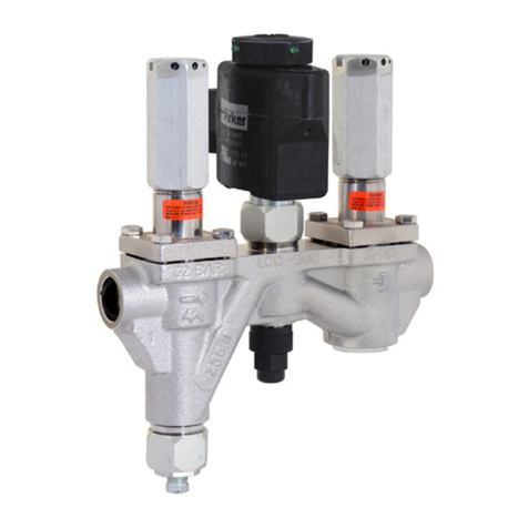
All CK-2W can be disassembled,
serviced and moving parts replaced
without disturbing the piping, but
of course, disassembly will cause
exposure of some section of piping
to atmosphere, which should be
addressed before disassembly
by evacuation and reclaim of the
refrigerant.
For the CK-2W series stop valve, the
high pressure supply line, passage
(P), should be removed prior to
disassembling the valve. e solenoid
coil (#2) should now be removed by
removing the coil clip (#1). Never
energize a solenoid coil that is not
mounted and secured on its solenoid
actuator (#3). e port plate, solenoid,
strainer, and pilot plug can remain
intact by removing the four bolts (#9).
e solenoid pseudo assembly (#3-7)
and the strainer (#12) can be replaced
with out the removal of the port plate.
Removal of the port plate may require
a sharp tap on their sides to unseat the
parts from their sealed position, for
which a rubber or rawhide hammer is
recommended so as to avoid damage
to the sealing surfaces. Removal of
the port plate will expose the top of
the piston. e piston spring (#30)
and piston (#29) should be removed
and inspected. Continue to inspect
the wear ring (#32), metal rings, and
gaskets.
Before re-assembly, all parts must
be cleaned with a suitable solvent,
permitted to dry, and lubricated with
a light lm of refrigerant oil, simply
wiped on with the ngers, All gaskets
and o-rings should be renewed, and
insertion and sealing will be facilitated
if a similar lm of oil is applied to them
as well.
Re-assembly is exactly the reverse
of disassembly, with the precaution
that the reliefs cut into each module
of the valve assembly and the
corresponding gaskets be aligned with
the appropriate location. Ensure that
all access ttings, solenoid features,
and bypass plug are sealed when
re-installing the corresponding parts.
Prior to installing the port plate inspect
the piston, using your hand, by pulling
up and pushing down. e piston
should move freely, without dragging
or hesitation. Adjust all torques
to the values indicated by torque
requirement table.
Tighten all bolts equally to draw the
assembly together evenly, to ensure
properly sealing of all joints.
Electrical
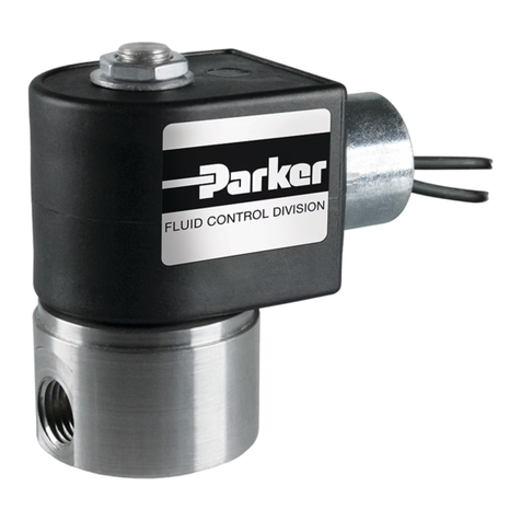
e Refrigerating Specialties Division
molded water resistant Class “H”
solenoid coil is designed for long
life and powerful opening force. e
standard coil housing meets NEMA
3R and 4 requirements. is sealed
construction can withstand direct
contact with moisture and ice. By def-
inition, Class “H” coil construction
will permit coil temperatures, as
measured by resistance method,
as high as 185°C. (366°F.) Final coil
temperatures are a function of both
uid and ambient temperatures. e
higher uid temperatures require
lower ambient temperatures for the
maximum coil temperature not to
be exceeded. Conversely, low uid
temperatures permit higher ambient
temperatures.
A solenoid coil should never be
energized except when mounted on its
corresponding solenoid tube.
e molded Class “H” coil is available
from stock with most standard
voltages. However, coils are available
for other voltages and frequencies, as
well as for direct current.
e solenoid coil must be connected
to electrical lines with volts and
Hertz same as stamped on coil. e
supply circuits must be properly
sized to give adequate voltage at the
coil leads even when other electrical
equipment is operating. e coil is
designed to operate with line voltage
from 85% to 110% of rated coil voltage.
Operating with a line voltage above or
below these limits may result in coil
burn-out. Also, operating with line
voltage below the limit will denitely
result in lowering the valve’s maximum
opening pressure dierential. Power
consumption during normal operation
will be 18.2 watts or less.
Caution
All personnel working on valves
must be qualied to work on
refrigeration systems. If there
are any question, contact
Refrigerating Specialties before
proceeding with the work.
Before doing any service work,
always be sure to disconnect
the power and isolate the valve.
Failure to do so will result in
venting of ammonia.
!
