manuals.online logo
Brands
  1. Home
  2. •
  3. Brands
  4. •
  5. Parker
  6. •
  7. Control Unit
  8. •
  9. Parker PK2 User manual

Parker PK2 User manual

Artisan Technology Group is your source for quality
new and certied-used/pre-owned equipment
• FAST SHIPPING AND
DELIVERY
• TENS OF THOUSANDS OF
IN-STOCK ITEMS
• EQUIPMENT DEMOS
• HUNDREDS OF
MANUFACTURERS
SUPPORTED
• LEASING/MONTHLY
RENTALS
• ITAR CERTIFIED
SECURE ASSET SOLUTIONS
SERVICE CENTER REPAIRS
Experienced engineers and technicians on staff
at our full-service, in-house repair center
WE BUY USED EQUIPMENT
Sell your excess, underutilized, and idle used equipment
We also offer credit for buy-backs and trade-ins
www.artisantg.com/WeBuyEquipment
REMOTE INSPECTION
Remotely inspect equipment before purchasing with
our interactive website at www.instraview.com
LOOKING FOR MORE INFORMATION?
Visit us on the web at www.artisantg.com for more
information on price quotations, drivers, technical
specications, manuals, and documentation
Contact us: (888) 88-SOURCE | sales@artisantg.com | www.artisantg.com
SM
View
Instra
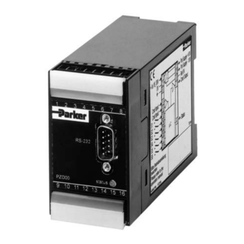
PK2 Packaged Stepper Drive
User Guide
1600.062.07—January, 1997
Compumotor
Compumotor Division
Parker Hannifin Corporation
p/n 88-007546-01A October 1997
Automation
Artisan Technology Group - Quality Instrumentation ... Guaranteed | (888) 88-SOURCE | www.artisantg.com
PK2 Packaged
Stepper Drive
User Guide
For engineering For engineering
assistance in Europe: assistance in the U.S.:
Parker Hannifin plc Parker Hannifin Corporation
Electromechanical Division - Digiplan Compumotor Division
21 Balena Close 5500 Business Park Drive, Suite D
Poole, Dorset Rohnert Park, CA 94928
England, BH17 7DX USA
Direct Lines for Technical Support Telephone: (800) 358-9070
Tel: 01202-699000 Fax: 01202-695750 Fax: (707) 584-3793
E-mail: [email protected] FaxBack System: (800) 936-6939
BBS: (707) 584-4059
E-mail: [email protected]Part No: 1600.062.07 Januar
y
, 1997
Artisan Technology Group - Quality Instrumentation ... Guaranteed | (888) 88-SOURCE | www.artisantg.com
IMPORTANT INFORMATION FOR USERS
Installation and Operation of Digiplan Equipment
It is important that Digiplan motion control equipment is installed and operated in such a way that all applicable
safety requirements are met. Note that it may be necessary for the completed installation to comply with the Low
Voltage Directive or Machinery Directive. It is your responsibility as an installer to ensure that you identify the
relevant safety standards and comply with them; failure to do so may result in damage to equipment and personal
injury. In particular, you should study the contents of this user guide carefully before installing or operating the
equipment.
The installation, set-up, test and maintenance procedures given in this User Guide should only be carried out by
competent personnel trained in the installation of electronic equipment. Such personnel should be aware of the
potential electrical and mechanical hazards associated with mains-powered motion control equipment - please see
the safety warning below. The individual or group having overall responsibility for this equipment must ensure that
operators are adequately trained.
Under no circumstances will the suppliers of the equipment be liable for any incidental, consequential or special
damages of any kind whatsoever, including but not limited to lost profits arising from or in any way connected with
the use of the equipment or this user guide.
!
SAFETY WARNING
High-performance motion control equipment is capable of producing rapid movement and very high forces.
Unexpected motion may occur especially during the development of controller programs.
KEEP WELL CLEAR
of
any machinery driven by stepper or servo motors. Never touch any part of the equipment while it is in operation.
This product is sold as a motion control component to be installed in a complete system using good engineering
practice. Care must be taken to ensure that the product is installed and used in a safe manner according to local
safety laws and regulations. In particular, the product must be enclosed such that no part is accessible while power
may be applied.
If the equipment is used in any manner that does not conform to the instructions given in this User Guide, then the
protection provided by the equipment may be impaired.
The information in this user guide, including any apparatus, methods, techniques, and concepts described herein,
are the proprietary property of Parker Digiplan or its licensors, and may not be copied, disclosed, or used for any
purpose not expressly authorised by the owner thereof.
Since Digiplan constantly strives to improve all of its products, we reserve the right to modify equipment and user
guides without prior notice. No part of this user guide may be reproduced in any form without the prior consent of
Digiplan.
© Digiplan Division of Parker Hannifin plc, 1997
– All Rights Reserved –
Artisan Technology Group - Quality Instrumentation ... Guaranteed | (888) 88-SOURCE | www.artisantg.com
CONTENTS i
CONTENTS
CONTENTS..............................................................................................................i
Chapter 1. GENERAL DESCRIPTION .........................................................................1
Chapter 2. INSTALLATION .......................................................................................5
Chapter 3. TROUBLESHOOTING..............................................................................19
Index.....................................................................................................................21
User Guide Change Summary
The following is a summary of the primary changes to this user
guide since the last version was released. This user guide, version
1600.062.07, supersedes version 1600.062.06.
When a user guide is updated, the new or changed text is
differentiated with a change bar in the outside margin (this
paragraph is an example). If an entire chapter is changed, the
change bar is located on the outside margin of the chapter title.
Major changes introduced at revision 07 are:
Change of mains fuse type for the 115V version
Warning symbols used on the PK2 series of drives have the following meanings:
Refer to the
accompanying documentation
Risk of electric shock
Hot surface
Protective conductor terminal
Alternating current
Frame or chassis terminal
Artisan Technology Group - Quality Instrumentation ... Guaranteed | (888) 88-SOURCE | www.artisantg.com
ii PK2 PACKAGED STEPPER DRIVE
Product Type: PK2 Packaged Stepper Drive
The above product is in compliance with the requirements of directives
•73/23/EEC Low Voltage Directive
•93/68/EEC CE Marking Directive
The PK2 drive is sold as a complex component to professional assemblers, as a component it is
not compliant with Electromagnetic Compatibility Directive 89/336/EEC.
Artisan Technology Group - Quality Instrumentation ... Guaranteed | (888) 88-SOURCE | www.artisantg.com
CHAPTER 1. GENERAL DESCRIPTION 1
Chapter 1. GENERAL DESCRIPTION
Introduction The PK2 bipolar stepper drive is a packaged version of the SD2
model, and has been designed primarily for single-axis applications.
It is suitable for most positioning applications and operates with a
wide range of motors. Incorporated in the drive is a toroidal mains
transformer, and all power supply components necessary for direct
operation from the AC mains supply. There is also an 8-way DIL
switch which enables the drive operating conditions to be
programmed, and a protection circuit guards against short circuits
across or between motor windings (not to ground). Additional
features include an internal oscillator, multi-turn preset controls and
standby circuit.
Two versions are available: PK2/115V and the PK2/230V. It is not
possible to change the voltage setting.
Specification Drive circuit Bipolar chopper-regulated with overload
protection
Switching sequence Full step or half step
Nominal output current 2A/phase (current may be set to lower
value by means of DIL switch)
Drive supply voltage 36v DC
Suitable motor type 4, 6, or 8-lead (5-lead not suitable)
Hybrid or Permanent magnet
Minimum motor inductance 1mH
Nominal chopping freq. 15kHz
Internal oscillator Slow (not ramped) 40-1,000 steps/sec
Speed ranges Fast (ramped) 400-10,000 steps/sec
Acceleration time 60mS
Deceleration time 30mS
These times may be increased by fitting
additional capacitor
Fault output circuit Open-collector NPN transistor
Fault output logic levels Low (transistor switched to 0v) +1v
max. at 25mA max.
High (transistor off) + 24v max.
Input impedance 4K7 pull-up to +12v
Table 1-1. PK2 Specifications
AC mains input
PK2/115V
PK2/230V 110 - 120V AC (±10%)
220 - 240V AC (±10%)
Input frequency range 47 - 63Hz
Input power 100VA
Ambient temperature range 0°-40°C
Artisan Technology Group - Quality Instrumentation ... Guaranteed | (888) 88-SOURCE | www.artisantg.com
2 PK2 PACKAGED STEPPER DRIVE
Dimensions 157mm x 76mm x 131mm
Weight 2Kg
Table 1-1. PK2 Specifications (continued)
157 (6.18) 76
(3.0)
Dimensions in mm(inches)
146 (5.74)
102
(4.0) 131
(5.15)
Figure 1-1. Dimensions in mm (inches)
Fuse Ratings One internal fuse is fitted to the drive power supply circuit. This is a
32mm time lag type with the following rating:
FS1 (motor supply DC fuse) 3.15A T LBC 6.3 x 32mm
There is also a mains fuse in the IEC mains input socket, accessible
from outside the enclosure, with the following rating:
For the 230V version
Mains connector fuse 1A T HBC 5 x 20mm
For the 115V version
Mains connector fuse 2A T HBC 5 x 20mm
LED
Functions There are two LEDs on the front of the drive, and their functions are
as follows:
"Power" LED (green): Indicates that power is applied to the drive.
"Fault" LED (red): Indicates that a fault condition has arisen.
Artisan Technology Group - Quality Instrumentation ... Guaranteed | (888) 88-SOURCE | www.artisantg.com
CHAPTER 1. GENERAL DESCRIPTION 3
Artisan Technology Group - Quality Instrumentation ... Guaranteed | (888) 88-SOURCE | www.artisantg.com
CHAPTER 2. INSTALLATION 5
Chapter 2. INSTALLATION
Installation
Mounting PK2 drives must be installed by competent personnel familiar with
the the installation, commissioning and operation of motion control
equipment. In the final application the equipment must be enclosed
to prevent the operator coming into contact with any high voltages.
The PK2 drives are not EMC compliant, they are sold as a complex
component for use by professional assemblers of motion control
systems.
Metal equipment cabinets offer the most advantages for siting the
equipment since they can provide operator protection, EMC
screening and can be readily fitted with interlocks arranged to
remove all AC power when the cabinet door is opened.
The drive may be mounted in any orientation. However, there are a
number of factors to be borne in mind when deciding on the location.
(a) The ambient temperature range for safe operation is 0°-40°C.
However, for continuous or high duty cycles and in applications
where the shaft power is more than 15 watts, forced cooling may be
necessary. It is therefore preferable for the drive to be mounted on
open rails to allow the maximum unobstructed air flow.
(b) Where there is a considerable distance between the control
system and the motor, the drive should generally be located as
close to the control system as possible. Long motor leads seldom
present a problem as long as they have a low resistance, but low-
level control signals may become prone to pickup or crosstalk
problems over long distances.
(c) For setting up purposes, it is desirable to have easy access to
the front panel of the drive. However, in the final installation,
operator access should be prevented.
A disconnect device must be provided which isolates all mains
supply current-carrying conductors. If the mains supply is
permanently connected, a switch or circuit breaker must be included
in the wiring. It must be placed close to the equipment (less than 1
metre) and marked as the disconnecting device for the equipment.
Artisan Technology Group - Quality Instrumentation ... Guaranteed | (888) 88-SOURCE | www.artisantg.com
6 PK2 PACKAGED STEPPER DRIVE
Specifications The operational temperature range for the drive system is:
• Operating Temperature: 0°to 40°C (32°to 102°F)
• Relative Humidity: 0% to 95% (non-condensing)
• Storage Temperature: -40°to 85°C (-40°to 185°F)
Refer to the manufacturer’s environmental specifications for the
maximum motor case temperature when it is in operation. This may
be a hazard to system operators.
The mains input to the drive must be Installation Category II
maximum.
PK2 drives can be used in a Pollution Degree 2 environment i.e.,
one in which only non-conductive pollution occurs.
You should install the drive system in an enclosure to protect it
against atmospheric contaminants such as oil, moisture, dirt and to
prevent operator access. In the USA, the National Electrical
Manufacturers Association (NEMA) has established standards that
define the degree of protection that electrical enclosures provide.
The enclosure should conform to NEMA Type 12 standards if the
intended environment is industrial and contains airborne
contaminants. Proper layout of components is required to ensure
sufficient cooling of equipment within the enclosure.
Mains Supply Using a minimum wire size of 24/0.2mm (18AWG) and the connector
supplied, the supply should be made to terminals marked L and N,
and the earth to the terminal marked E. Use approved mains cable
for the supply and keep it separate from the motor and signal wiring.
The equipment must be earthed.
Two versions of the drive are available:
PK2/115V
PK2/230V
The voltage setting cannot be changed.
Motor Connections Use16/0.2mm (20 AWG, CSA 0.5mm2) wire (or larger) for motor
connections.
Connect the motor leads to terminals 1A, 1B, 2A and 2B using the
connection data supplied. Connect one phase of the motor to
terminals 1A and 1B, and the other phase to terminals 2A and 2B.
To reverse the direction of rotation relative to the direction control
input, interchange the connections to 1A and 1B (see page 11).
It can be seen in Figure 2-1 that the motor windings may be
connected either in series or parallel. The preferred connection
Artisan Technology Group - Quality Instrumentation ... Guaranteed | (888) 88-SOURCE | www.artisantg.com
CHAPTER 2. INSTALLATION 7
mode depends on the application since the performance
characteristics differ (see Figure 2-2).
Series connection gives double the ampere-turns of a single coil at a
given current and there is therefore a significant increase in low-
speed torque. However, the inductance per phase is increased to
four times the inductance of one coil, causing the high-speed torque
to drop off more rapidly.
Parallel connection on the other hand results in less torque at low
speeds, but the torque will be maintained to higher stepping rates.
The maximum power obtainable from the motor is greater in the
parallel mode. With a six-lead motor, the two halves of each winding
cannot be connected in parallel. However, using one half of each
winding produces the same torque as an equivalent 8-lead motor
connected in parallel. The advantage of parallel connection is a
reduction in resistive losses which allows a higher current to be
used.
It is most important that any unused motor leads are individually
insulated, and under no circumstance should they be joined together
unless this is specified in the motor connection data. Do not
attempt to use a 5-lead motor with this drive.
NOTE: If the PK2 was sold with a QM or RM motor (sold in the
USA) refer to the "Digiplan Motor User Guide" supplied with the
motor, or call Digiplan USA. This motor user guide contains
complete wiring and current information for these motors.
6 OR 8 LEAD IN SERIES8 LEAD IN PARALLEL4 LEAD
1A
1B
2A
2B
1A
1B
2A
2B2B
2A
1B
1A
Figure 2-1. Motor Connection Methods
Artisan Technology Group - Quality Instrumentation ... Guaranteed | (888) 88-SOURCE | www.artisantg.com
8 PK2 PACKAGED STEPPER DRIVE
PARALLEL
DRIVE SET
AT 2A
0.1
RPM
TORQUE Nm
MOTOR:2.3-INCH 1-STACK 2.1A/PHASE
FULL STEP/SEC x 1000
SERIES (DRIVE
SET AT 1.5A) 50
40
30
20
10
00
0.2
0.3
0.4
543210
150012009006003000
RPM
TORQUE Nm
PARALLEL
SERIES
MOTOR:2.3-INCH 3-STACK 4.6A/PHASE
FULL STEPS/SEC x 1000
0
20
40
60
80
100
0.8
0.6
0.4
0
0.2
012345
150012009006003000
Figure 2-2. Typical Performance Characteristic Curves
Motor Cable
The recommended gauge for PK2 drives is greater or equal to
0.5mm2. Use a cable containing four conductors plus the braided
screen. The temperature rating of the cable must be greater than or
equal to the motor case temperature and should be at least 80°C.
Motor Earth
The motor body must be reliably earthed.
WARNING: The case of a motor can become very hot.
Precautions may need to be taken to prevent operator contact.
Artisan Technology Group - Quality Instrumentation ... Guaranteed | (888) 88-SOURCE | www.artisantg.com
CHAPTER 2. INSTALLATION 9
N.C. - no connection.
MAKE TYPE 1A 1B 2A 2B NOTES
Evershed & Vignoles 6-lead Red Green Blue Yellow Brown & Black N.C.
8-lead Red Green Blue Yellow Link Grey & Pink, link
White & Violet
T.box 1 3 4 2 Link 5 & 6, link 7 & 8
Sigma 6-lead Black Orange Red Yellow White/Blk/Org,
White/Red/Yel N.C.
8-lead Black Orange Red Yellow Link Wh/Blk & Wh/Org
Link Wh/Red & Wh/Yel
T.box 1 3 2 4 Link 5 & 6,link 7 & 8
Astrosyn, 6-lead Red Red/Wh Grn Grn/Wh White & Black N.C.
Rapidsyn,
Slo-syn T.box (x6) 1 3 4 5 2 & 6 N.C.
Slo-syn 8-lead Red Red/Wh Grn Grn/Wh Link Black & White, link
Org & Blk/Wh
T.box (x8) 1 3 5 4 Link 2 & 6, link 7 & 8
Stebon 8-lead Red Yel Pink Blk Link Blue & violet, link
White & Grey
T.box 1 2 3 4 Link 5 & 6, link 7 & 8
G.E.C. T.box 1 2 3 4 Link 5 & 6, link 7 & 8
M.A.E. 6-lead Grn/Wh Grn Red Red/Wh White & Black N.C.
8-lead Black Orange Red Yellow Link Wh/Blk & Wh/Org,
Link Wh/Red & Wh/Yel
T.box 6 5 8 7 Link 1 & 3, link 2 & 4
Zebotronics T.box 1 4 5 8 Link 2 & 3, link 6 & 7
Oriental 6-lead Black Green Red Blue Yellow & White N.C.
Sonceboz 8-lead Green Grn/Wh Red Red/Wh Link Org & Blk/Wh, link
Black & White
Japan Servo 6-lead Red Blue Green Yellow 2 x White N.C.
Escap 8-lead Brown Org/Wh Red Yel/Wh Link Brn/Wh & Org,
Link Red/Wh & Yellow.
Bodine 8-lead Brown Orange Yellow Red Link Wh/Brn & Wh/Org,
link Wh/Yel & Wh/Red.
T.box 1 3 4 2 Link 5 & 7,link 6 & 8
Digiplan/Compumotor
RM Motor 8-lead Black Orange Red Yellow LinkWh/Blk & Wh/Org.
Link Wh/Red & Wh/Yel
Digiplan/Compumotor
QM Motor 8-lead Red Black White Green Link Yel & Blue
Link Org & Brown
Table 2-1. Motor Connection Data - Windings in Series
Artisan Technology Group - Quality Instrumentation ... Guaranteed | (888) 88-SOURCE | www.artisantg.com
10 PK2 PACKAGED STEPPER DRIVE
N.C. - no connection. For 6-lead motors, connections shown are for one half-winding.
MAKE TYPE 1A 1B 2A 2B NOTES
Evershed & Vignoles 6-lead Red Brown Blue Black Grn & Yellow N.C.
8-lead Rd & Grn & Blue & Yel &
Pink Grey Violet White
T.box 1 & 6 3 & 5 4 & 8 2 & 7
Sigma 6-lead Black Wh/Blk/ Red Wh/Red/ Or & Yellow N.C.
Orange Yellow
8-lead Black & Or & Red/ Yel &
Wh/Or Wh/Blk Wh/Yel Wh/Red
T.box 1 & 5 3 & 6 2 & 7 4 & 8
Astrosyn, 6-lead Red Black Green White Red/Wh &
Rapidsyn, Grn/Wh N.C.
Slo-syn T.box(x6) 1 6 4 2 3 & 5 N.C.
Slo-syn 8-lead Red & Blk & Grn & Org &
White Red/Wh Blk/Wh Grn/Wh
T.box(x8) 1 & 2 3 & 6 4 & 7 5 & 8
Stebon 8-lead Rd & Yel & Wh & Black &
Blue Violet Pink Grey
T.box 1 & 6 2 & 5 3 & 8 4 & 7
G.E.C. T.box 1 & 6 2 & 5 3 & 8 4 & 7
M.A.E. 6-lead Grn/Wh White Red Black Grn & Red N.C
8-lead Black & Or & Red & Yel &
Wh/Or Wh/Blk Wh/Yel Wh/Red
T.box 3 & 6 1 & 5 4 & 8 2 & 7
Zebotronics T.box 1 & 2 3 & 4 5 & 6 7 & 8
Oriental 6-lead Black Yellow Red White Grn & Blue N.C.
Sonceboz 8-lead Grn & Or & Red & Blk &
Blk/Wh Grn/Wh White Red/Wh
Japan Servo 6-lead Red White* Green White*
Escap 8-lead Brn & Brn/Wh & Red & Red/Wh &
Orange Org/Wh Yellow Yel/Wh
Bodine 8-lead Brn & Wh/Brn & Yel & Wh/Yel &
Wh/Or Orange Wh/Red Red
T.box 1 & 7 3 & 5 4 & 6 2 & 8
Digiplan/Compumotor
RM Motor 8-lead Black & Orange & Red & Yellow &
Wh/Or Wh/Black Wh/Yellow Wh/Red
Digiplan/Compumotor
QM Motor 8-lead Red & Blue Blk & Yellow Wh & Brn Green & Org
* Use correct White for each phase.
Table 2-2. Motor Connection Data - Windings in Parallel
Artisan Technology Group - Quality Instrumentation ... Guaranteed | (888) 88-SOURCE | www.artisantg.com
CHAPTER 2. INSTALLATION 11
Control Signal
Connections All control signals and motor connections are made to a two-part
terminal block.
Signal connections should be made with a minimum wire size of
7/0.2mm (24 AWG). To reduce the effect of radiated electrical noise
it is suggested to use screened cable for all control signals and care
should be taken to ensure that the screen is grounded at one end
only.
Description of
Terminal
Functions
1A, 1B, 2A and 2B: refer to motor connections on page 4.
0v
: Use this terminal as the common return point for the control
signals.
Fault output
: This is an open-collector output which goes high in the
event of a drive fault (overload or supply failure). The maximum on-
state current is 25mA and the maximum off-state voltage +24v.
If a relay is used at this output, a diode (IN4148 recommended),
should be connected across its energising coil, as shown in Figure
2-3, to protect against damage to the output transistor by reverse
voltage when the coil is de-energised.
FAULT OUTPUT
IN4148 RELAY
+ SUPPLY
Figure 2-3. Typical Relay Output Circuit
Artisan Technology Group - Quality Instrumentation ... Guaranteed | (888) 88-SOURCE | www.artisantg.com
12 PK2 PACKAGED STEPPER DRIVE
Energise/Reset
: This input enables the motor to be de-energised
and also resets a fault condition, provided the cause of the fault has
been removed. When the input is taken high, the drive will be de-
energised and if it is safe to do so, the motor shaft may be rotated
slowly by hand. Taking the input high will also reset a fault
condition, and the drive will re-energise when the input returns low.
The "energise" switch must be off when this terminal is being used.
Dirn.
: Connect to 0v to reverse the direction of motor rotation.
Ck. in
: The motor will step following a low-going transition on this
input. The input should remain low for at least 10µS. This input is
driven from the internal oscillator on the drive but can also be driven
from an external source.
Slow
: Connect to 0v to run the internal oscillator at the slow rate.
Fast
: Connect to 0v to run the internal oscillator at the fast rate.
Fast Adj.
: An external potentiometer may be connected between
this terminal and Adj. com. to control the fast speed of the internal
oscillator. A suitable value for the external resistor is 10K.
Adj. Com.
: Common return connection for external speed controls.
Slow Adj.
: An external potentiometer may be connected between
this terminal and Adj. com. to control the slow speed of the internal
oscillator. A suitable value for the external resistor is 100K.
Note that the direction, energise and clock inputs are all pulled-up
internally to +12v via a 4K7 resistor. These inputs should therefore
be driven from an open-collector output or manual switch as
appropriate.
Adjustments
Switch Settings Beside the terminal block is an 8-way DIL switch for setting the drive
operating conditions, and in most applications this will be the only
adjustment required.
Switch 1: Energ.
Turn on to permanently energise the drive. A fault
condition can be reset by momentarily turning switch 1 off.
Switch 2: Mode
Turn on to select the full step mode and off to select
the half step mode. Do not change the mode of operation whilst the
drive is powered-up.
Artisan Technology Group - Quality Instrumentation ... Guaranteed | (888) 88-SOURCE | www.artisantg.com
CHAPTER 2. INSTALLATION 13
Switches 3-6: Current set
The following table gives the settings of
these four switches for various motor currents. The actual motor
current will depend partly on winding inductance, a lower inductance
giving a lower average current. Note that the drive current is
reduced by approximately 50% at standstill.
Nominal current Switch settings
3456
2.0A off off off off
1.8A off off off on
1.6A off off on off
1.4A off on off on
1.2A off on on on
1.0A on off off off
See note on page 4 for USA RM and QM motor current settings
Table 2-3. Settings for Switches 3 to 6
Switch 7: Slow
The internal slow speed adjustment is in circuit
when this switch is on. Turn off when using an external speed
control.
Switch 8: Fast
The internal fast speed adjustment is in circuit when
this switch is on. Turn off when using an external speed control.
Internal Oscillator
Ramping The preset acceleration and deceleration times on the internal
oscillator are 60µS and 30µS respectively. These times may be
extended by the addition of capacitor C23, a value of 10µF will give
approximately double the preset times. Use a dipped tantalum
capacitor rated at 25 volts and observe the polarity. The capacitor
should be top-soldered to the board, keeping the legs as short as
possible. The location for C23 is at the side of the board close to the
serial number (see "Removal and Replacement of the Top Cover").
Artisan Technology Group - Quality Instrumentation ... Guaranteed | (888) 88-SOURCE | www.artisantg.com
14 PK2 PACKAGED STEPPER DRIVE
ENERGISE
EXT CLOCK IN
2B
2A
1B
1A
0V
FAULT
ENERGISE/RESET
DIRN
CLOCK IN
SLOW
FAST
FAST ADJ
ADJ COM
SLOW ADJ
CURRENT SET
MODE
SLOW
FAST
OFF
FAST
SLOW
FAULT
POWER
MOTOR
AC
MAINS
INPUT
FAST
SLOW
DIRECTION
OPTIONAL EXTERNAL
SPEED CONTROLS
Figure 2-4. Typical Motor and Control Connections
Artisan Technology Group - Quality Instrumentation ... Guaranteed | (888) 88-SOURCE | www.artisantg.com

Other Parker Control Unit manuals

Parker Hi-Pro Manifold User manual

Parker

Parker Hi-Pro Manifold User manual

Parker S8VS User manual

Parker

Parker S8VS User manual

Parker 2B4 Series User manual

Parker

Parker 2B4 Series User manual

Parker DxFB Series User manual

Parker

Parker DxFB Series User manual

Parker BAM20 User manual

Parker

Parker BAM20 User manual

Parker PACHC Series User manual

Parker

Parker PACHC Series User manual

Parker PSSNACM12A Installation and maintenance instructions

Parker

Parker PSSNACM12A Installation and maintenance instructions

Parker Racor 200 Series User manual

Parker

Parker Racor 200 Series User manual

Parker DFB Series User manual

Parker

Parker DFB Series User manual

Parker PQDXXA-Z10 Installation and operation manual

Parker

Parker PQDXXA-Z10 Installation and operation manual

Parker D*1VW*EE Series User manual

Parker

Parker D*1VW*EE Series User manual
Parker TDP Series User manual

Parker

Parker TDP Series User manual

Parker D1FB EE Series User manual

Parker

Parker D1FB EE Series User manual

Parker EBV-PR Series User guide

Parker

Parker EBV-PR Series User guide

Parker D 1FC Series User manual

Parker

Parker D 1FC Series User manual

Parker PIO-400 User manual

Parker

Parker PIO-400 User manual

Parker Vansco User manual

Parker

Parker Vansco User manual

Parker S7A Service manual

Parker

Parker S7A Service manual

Parker PID00A-40 Series User manual

Parker

Parker PID00A-40 Series User manual

Parker PID00A-40X Series User manual

Parker

Parker PID00A-40X Series User manual

Parker SciLog DINCon Assembly instructions

Parker

Parker SciLog DINCon Assembly instructions

Parker LINKnet TechBox Series User manual
Parker

Parker LINKnet TechBox Series User manual

Parker C2 Series Installation and maintenance instructions

Parker

Parker C2 Series Installation and maintenance instructions

Parker D1VW -SC Series User manual

Parker

Parker D1VW -SC Series User manual

Popular Control Unit manuals by other brands

Tews Technologies TIP866-TM-20 user manual

Tews Technologies

Tews Technologies TIP866-TM-20 user manual

REMS CamSys Instructions for installing

REMS

REMS CamSys Instructions for installing

BFT BOX Installation and user manual

BFT

BFT BOX Installation and user manual

Wilo Wilo-Control EC-L Installation and operating instructions

Wilo

Wilo Wilo-Control EC-L Installation and operating instructions

E+E Elektronik EE1900 user manual

E+E Elektronik

E+E Elektronik EE1900 user manual

Mitsubishi MELSEC QD75P user manual

Mitsubishi

Mitsubishi MELSEC QD75P user manual

Mitsubishi NZ2GF2B-60DA4 user manual

Mitsubishi

Mitsubishi NZ2GF2B-60DA4 user manual

Baumuller BM4-O-CAN-06 operating instructions

Baumuller

Baumuller BM4-O-CAN-06 operating instructions

MFB OSC-02 operating manual

MFB

MFB OSC-02 operating manual

Telit Wireless Solutions BlueMod+S50/AI Hardware user's guide

Telit Wireless Solutions

Telit Wireless Solutions BlueMod+S50/AI Hardware user's guide

Thetford 23709 manual

Thetford

Thetford 23709 manual

resideo Braukmann BFW112 Operating and maintenance manual

resideo

resideo Braukmann BFW112 Operating and maintenance manual

Wolf BML-EXCELLENT user manual

Wolf

Wolf BML-EXCELLENT user manual

Task Force Tips PA2BF-L instructions

Task Force Tips

Task Force Tips PA2BF-L instructions

Geberit DuoFresh user manual

Geberit

Geberit DuoFresh user manual

CALEFFI AIR190001 manual

CALEFFI

CALEFFI AIR190001 manual

Puls DIMENSION YR40.245 manual

Puls

Puls DIMENSION YR40.245 manual

Eaton ELC-CADNET instruction sheet

Eaton

Eaton ELC-CADNET instruction sheet

manuals.online logo
manuals.online logoBrands
  • About & Mission
  • Contact us
  • Privacy Policy
  • Terms and Conditions

Copyright 2025 Manuals.Online. All Rights Reserved.