PEERLESS 62630166 User manual

1
62403561 R00_USA 05-06-2012
X
conversion kit for boilers model 160.
P/N 62630166 N
A
TURAL to LP GAS
P/N 62630167 LP to NATURAL GAS
conversion kit for boilers model 160.
W
ARNING!!!
This conversion kit shall be installed by
a qualified service agency in accordance
with the manufacturer’s instructions and
all applicable codes and requirements
of the authority having jurisdiction. The
information in these instructions must
be followed to minimize the risk of fire
or explosion or to prevent property
damage, personal injury or death. The
qualified service agency is responsible
for the proper installation of this kit. The
installation is not proper and complete
until the operation of the converted
appliance is checked as specified in the
manufacturer’s instructions supplied
with the kit.
W
ARNING!!!
THE CONVERSION SHALL
BE
CARRIED OUT
INACCORDANCE
WITH THE REQUIREMENTS OF
THE
PROVINCIAL AUTHORITIES
HAVING
JURISDITION AND
IN
ACCORDANCE
WITH THE REQUIREMENTS OF
THE
ANSI Z223.1/NFPA
54,
CAN-B149.1
AND
CAN1-B149.2 INSTALLATION
CODE.
AVERTISSEMENT!!!
Cette trousse de conversion ne doit être
installée que par le représentant d’un
organisme qualifié et conformément
aux instructions du fabricant et à tous
les codes et exigences pertinents de
l’autoritè compétente. Les instructions
de cette notice doivent être suivie afin de
réduir au minimum le risque d’incendie
ou d’explosion, de dommage matériel,
de blessure ou de mort. L’organisme
qualifié est responsable de l’installation
adéquate de cette trousse. L’installation
n’est pas adéquate ni complète tant
que le bon fonctionnement de l’appareil
converti n’a pas été vérifié selon les
instructions du fabricant fournies avec
la trousse.
AVERTISSEMENT!!!
LA CONVERSION DOIT ÊTRE
EFFECTUÉE CONFORMÉMENT
AUX EXIGENCES DE L’AUTORITÉ
PROVINCIALEAYANT JURISDICTION
ET AUX CODES D’INSTALLATION
ANSI Z223.1/NFPA 54, CAN-B149.1
ET CAN-B149.2.

2
1 - Convert the
boiler from Natural
Gas to Propane gas
or viceversa
Contents:
This conversion kit is composed of
the following elements, which are
necessary for the gas change:
- a label rating the new gas setting;
- this instruction sheet;
- an orice (see Table 1 for the
stamping reference);
Installing:
in order to make the gas change
please follow the instructions below:
1 - turn off power to the boiler;
2 - open the boiler’s casing;
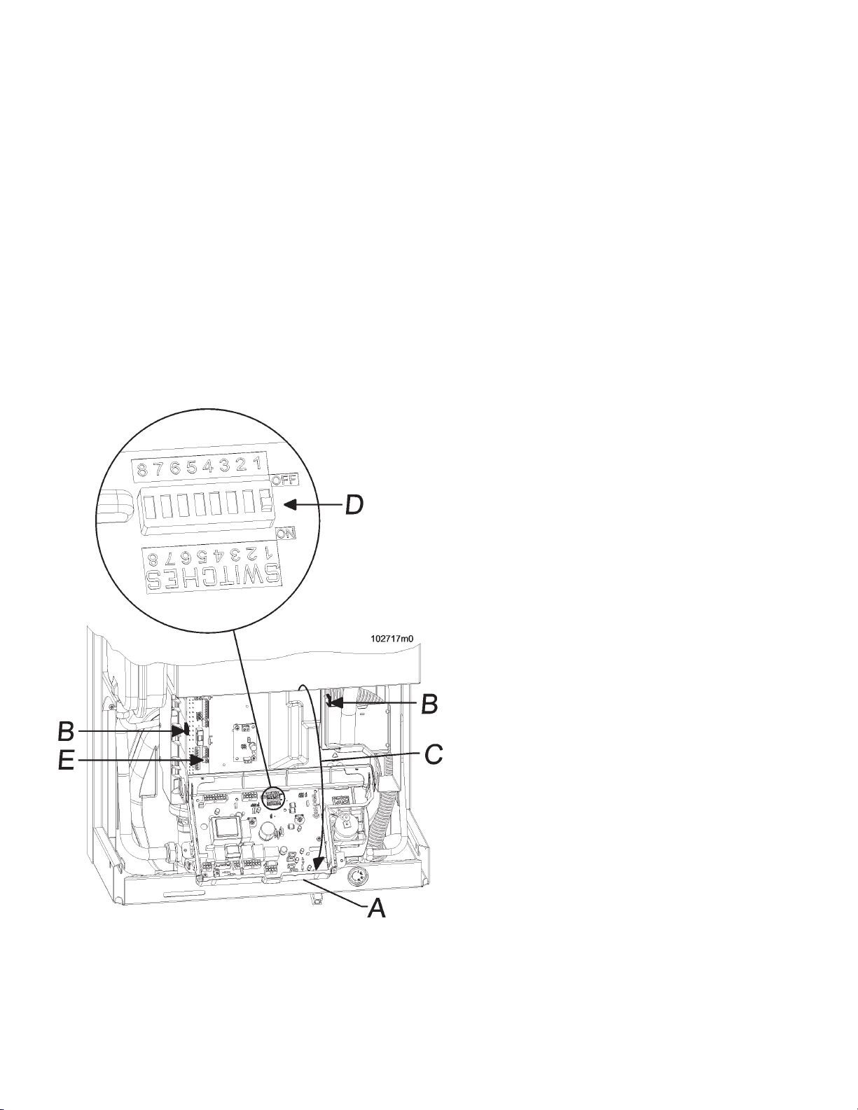
3 - open the instrument panel (Follow
Section 2);
4 - Move switch #7 (see Figure 4)
from OFF position to ON position;
5 - turn on power to the boiler;
6 - on the boiler’s display you’ll see
followed by a number;
7 - using the push buttons and
set the input to:
- 61 to convert the boiler from LP
GAS to NATURAL GAS
or
- 62 to convert the boiler from
NATURAL GAS to LP GAS,
8 - push button to save the
new value;
9 - turn off power to the boiler;
10 - Move switch #7 (see Figure 4)
from ON position to OFF position;
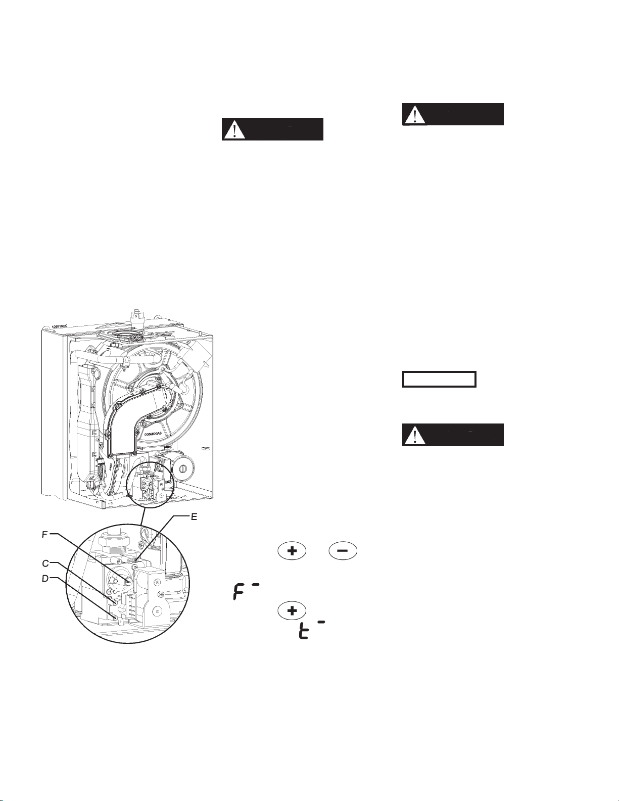
11 - Replace the orice item “C” of
Figure 1 for the correct one for the
type of gas used. Verify that the
stamping on the orice matches the
gas type (See Table 1).
11 - turn on power to the boiler;
12 - Turn completely counter
clockwise the screw E of Figure 1;
13 - Checking gas supply pressure
following Section 3. The Gas supply
pressure must be between the
maximum and minimum value as
stated in Table 1.
14 - Verifying the CO2 rate and its
eventual adjustment following
Section 4: The boiler during its
normal operation, has a CO2
exhaust rate as shown in Table 1.
If not within range of value shown,
malfunctions will occur.
WARNING!!!
WARNING!!! The CO
(carbon monoxide) level should
not exceed values given in
Table 1, when combustion is
correct. Failure to comply with
this requirement could result in
severe personal injury, death or
substantial property damage.
Gas Type TY value
setting
Min.
supply
pressure
Max.
supply
pressure
Orice CO2
content at
high re
CO2
content at
low re
O2
content at
high re
O2 content
at low re
CO content at
high and low re
/ / in.W.C. in.W.C. Stamping % % % % ppm
Natural gas 61 3 13 9.1 9.2 ± 0.1 8.7 ± 0.3 4.5 ± 0.1 5.4 ± 0.3 less than 150
LP gas 62 3 13 5.7 9.5 ± 0.2 9.5 ± 0.3 6.4 ± 0.2 6.4 ± 0.3 less than 250
Table 1 - Settings of the boiler for NATURAL GAS and LP GAS
WARNING!!!
WARNING!!! All
combustion measurements
must be performed with
calibrated equipment to ensure
proper reading and accuracy.
Failure to comply with this
requirement could result in
severe personal injury, death or
substantial property damage.
WARNING!!!
WARNING!!! If the
combustion levels are not
within the range given in
Table 1 for the ring rate, shut
the boiler down and contact
your distributor or the boiler
manufacturer (see reference in
the last cover page). Failure to
comply with this requirement
could result in severe personal
injury, death or substantial
property damage.
15 - Attach to the front of the boiler the
appropriate conversion label, found
in the conversion kit (see Figure 2
or Figure 3), stating the new type of
gas adjustment of the boiler.
a - Apply the label in Figure 3 if the
boiler has been converted to LP
GAS;
b - Apply the label in Figure 2 if the
boiler has been converted to
NATURAL GAS.

3
A = Fixing nut
B = Gasket
C = Orice
D = Brass tting
E = CO2 / O2 regulator
Figure 2 - Label for Natural gas boiler Figure 3 - Label for LP gas boiler
Figure 1 - Gas valve

4
A = Front cover of the electrical box
B = Plastic spring to open the electrical box
C = Direction to open the electrical box
D = Switches for the functional setting of the boiler
Figure 4 - Control board and unit electrical box details
2 - Opening the
instrument panel
To open the instrument panel and gain
access to the boiler control board,
follow this procedure:
1. disconnect the boiler from the
electrical supply;
2. remove the boiler;
3. push the plastic spring tabs “B”
shown in Figure 4;
4. open the front half of the electrical
box in the “C” direction as shown in
Figure 4;

5
Figure 5 - Gas valve
C - Service pressure probe
D - Inlet gas pressure probe
E - CO2 adjusting screw
F - Factory adjusted regulator
(Should never be touched)
3 - Gas supply
pressure checking
WARNING!!!
WARNING!!! DO NOT
adjust or attempt to measure
gas valve outlet pressure. The
gas valve is factory-set for the
correct outlet pressure. This
setting is suitable for natural
gas and propane, requiring no
eld adjustment. Attempting
to alter or measure the gas
valve outlet pressure could
result in damage to the gas
valve, causing potential severe
personal injury, death, or
substantial property damage.
Check the gas supply pressure by
following the steps below:
1. close the manual gas shut-off valve
(must be near to the boiler);
2. remove the front cover;
3. turn the screw in pressure port
“D” shown in Figure 5 three turns
counterclockwise;
4. connect a manometer with
graduations of at least 0.1 in.W.C.
(0.25 mbar) to the inlet gas port “D”
shown in Figure 5;
5. open the manual gas shut off valve;
6. check that the gas supply pressure
does not exceed 13 in.W.C.;
7. turn the power switch to on and
generate a heat demand by turning
the heating temperature control
knob (see boiler’s installation
manual) to its maximum setting.
Also ensure that the room
thermostat is calling for heat;
8. press the and keys
at the same time for more than
10 seconds, the display will show
;
9. press the key until the
display shows . Now the
boiler will run for 10 minutes at
maximum input;
10. check the manometer to make
sure the gas supply pressure does
not drop below 3 in.W.C. (7.6
mbar).
If the gas supply pressure does not
fall within 3 and 13 in.W.C. adjust the
upstream gas pressure regulator to
bring the gas supply pressure within 3
and 13 in.W.C..
WARNING!!!
WARNING!!! DO NOT
adjust the screws “E” and/or
“F” of Figure 5. These screws
are factory-set for the correct
gas ow and outlet pressure.
Attempting to alter the gas
valve setting could result in
damage to the valve, causing
potential severe personal
injury, death, or substantial
property damage.
After verifying the correct gas
pressures:
1. close the manual gas shut-off
valve;
2. disconnect the manometer;
3. turn the screw in pressure
connection “D” in Figure 5,
clockwise until snug;
4 check for any gas leaks with a soap
solution.
CAUTION!!! Never force the
pressure connection screw or
the gas valve will be damaged!
WARNING!!!
WARNING!!! Never use an
open ame to check for gas
leaks, a re or an explosion
could result causing severe
personal injury or death!

6
A = air probe
B = ue exhaust probe
C = O-ring gaskets
D = cap
E = xing screw
Figure 6 - Combustion
analysis probes
4 - Checking and
adjusting CO2 levels
Table 1 lists the correct CO2 ranges
for a boiler running at normal operating
conditions. CO2 values outside of the
ranges given in Table 1 may lead to
malfunctioning of the boiler and cause
it to prematurely fail. To check the CO2
value, carry out a combustion analysis
as follows while referencing Figure 6:
WARNING!!!
WARNING!!!
During this
procedure compare also CO
(carbon monoxide) reading, with
the value given in Table 1. When
CO2 value is correct, if the CO
content is higher than the stated
on Table 1, STOP the boiler
and call the Factory service
department (see reference on
the last cover page). Failure to
comply with this requirement
could result in severe personal
injury, death or substantial
property damage.
NOTE: During the 10 minutes
override mode, if the demand on
the boiler is low causing the ue
gas temperature to increase rapidly,
boiler will go into lock out code L06.
To reactivate it, press button.
1. carefully remove items “E”, “D” and
“C” from the combustion air/vent
tting:
2. generate a call for heat; and wait up
the boiler is light-on;
4. press the and keys for
more than 10 seconds, the display
will show a blinking ;
5. press the key until the display
shows
if a call for heat has
been generated or until is
displayed if a domestic hot water
demand has been generated
.The
boiler will now run for 10 minutes at
high re input;
6. wait 2 to 3 minutes for the CO2 to
stabilize;
7. insert the probe of a calibrated
combustion analyzer into port “B” and
take a ue gas sample;
8. compare the CO2 reading with the
high re range given in Table 1,
making sure to use the range for the
gas type in use. If the CO2 reading
is outside the specied range, it must
be adjusted operating on the “E”
screw of Figure 6. Use a 2.5mm Allen
Wrench to turn the screw (clockwise
to reduce the CO2 level, counter-
clockwise to increase the CO2
level) in small increments and wait
for the CO2 to stabilize to prevent
overshooting the desired value;
9. When CO2 level match the value
of Table 1, seal screw “E” with red
paint or nail polish to discourage
tampering.
10. press the key until the
display shows
if a call for heat
has been generated or until
is displayed if a domestic hot water
demand has been generated
. The
boiler will now run for 10 minutes at
low re input;
11. wait 2 to 3 minutes for the CO2 to
stabilize;
12. compare the CO2 reading with the
low re range given in Table 11-3,
making sure to use the range for the
gas type in use. The CO2 reading
must be inside the specied range;
If not, STOP the boiler and call the
Factory service department (see
reference on the last cover page).
13. press the button to return the
boiler to its normal operating mode.
14. close ue and air probe “A” and “B”
of Figure 6.
This manual suits for next models
1