manuals.online logo
Brands
  1. Home
  2. •
  3. Brands
  4. •
  5. Pepperl+Fuchs
  6. •
  7. Accessories
  8. •
  9. Pepperl+Fuchs NCB4-12GM40-N0-V1 User manual

Pepperl+Fuchs NCB4-12GM40-N0-V1 User manual

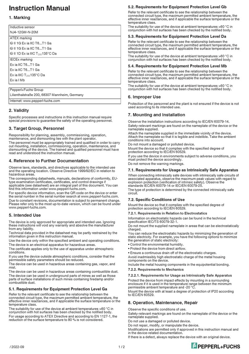
Instruction Manual
1. Marking
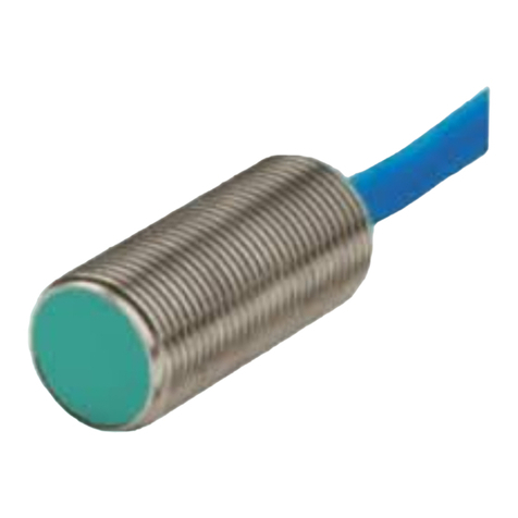
Inductive sensor
NCB4-12GM40-N0-V1
ATEX marking
1 II 1G Ex ia IIC T6...T1 Ga
1 II 1D Ex ia IIIC T200135°C Da
1 II 3D Ex tc IIIC T80°C Dc
IECEx marking
Ex ia IIC T6...T1 Ga
Ex ia IIIC T200135°C Da
Ex tc IIIC T80°C Dc
Ex ia I Mb
Pepperl+Fuchs Group
Lilienthalstraße 200, 68307 Mannheim, Germany
Internet: www.pepperl-fuchs.com
2. Validity
Specific processes and instructions in this instruction manual require
special provisions to guarantee the safety of the operating personnel.
3. Target Group, Personnel
Responsibility for planning, assembly, commissioning, operation,
maintenance, and dismounting lies with the plant operator.
The personnel must be appropriately trained and qualified in order to carry
out mounting, installation, commissioning, operation, maintenance, and
dismounting of the device. The trained and qualified personnel must have
read and understood the instruction manual.
4. Reference to Further Documentation
Observe laws, standards, and directives applicable to the intended use
and the operating location. Observe Directive 1999/92/EC in relation to
hazardous areas.
The corresponding datasheets, manuals, declarations of conformity, EU-
type examination certificates, certificates, and control drawings if
applicable (see datasheet) are an integral part of this document. You can
find this information under www.pepperl-fuchs.com.
For specific device information, scan the QR code on the device or enter
the serial number in the serial number search at www.pepperl-fuchs.com.
Due to constant revisions, documentation is subject to permanent change.
Please refer only to the most up-to-date version, which can be found under
www.pepperl-fuchs.com.
5. Intended Use
The device is only approved for appropriate and intended use. Ignoring
these instructions will void any warranty and absolve the manufacturer
from any liability.
Technical data provided in the datasheet may be partly restrained by the
information given in this instruction manual.
Use the device only within the specified ambient and operating conditions.
The device is an electrical apparatus for hazardous areas.
The certificate applies only to the use of apparatus under atmospheric
conditions.
If you use the device outside atmospheric conditions, consider that the
permissible safety parameters should be reduced.
The device can be used in hazardous areas containing gas, vapor, and
mist.
The device can be used in hazardous areas containing combustible dust.
The device can be used in underground parts of mines as well as those
parts of surface installations of such mines containing firedamp and/or
combustible dust.
5.1. Requirements for Equipment Protection Level Ga
Refer to the relevant certificate to see the relationship between the
connected circuit type, the maximum permitted ambient temperature, the
effective inner reactances, and if applicable the surface temperature or the
temperature class.
The suitability for use of the device at ambient temperatures >60 °C in
conjunction with hot surfaces has been checked by the notified body.
For usage according to ATEX Directive and according to EN 1127-1, the
reduction of the surface temperature to 80 % is not considered.
5.2. Requirements for Equipment Protection Level Gb
Refer to the relevant certificate to see the relationship between the
connected circuit type, the maximum permitted ambient temperature, the
effective inner reactances, and if applicable the surface temperature or the
temperature class.
The suitability for use of the device at ambient temperatures >60 °C in
conjunction with hot surfaces has been checked by the notified body.
5.3. Requirements for Equipment Protection Level Da
Refer to the relevant certificate to see the relationship between the
connected circuit type, the maximum permitted ambient temperature, the
effective inner reactances, and if applicable the surface temperature or the
temperature class.
The suitability for use of the device at ambient temperatures >60 °C in
conjunction with hot surfaces has been checked by the notified body.
5.4. Requirements for Equipment Protection Level Mb
Refer to the relevant certificate to see the relationship between the
connected circuit type, the maximum permitted ambient temperature, the
effective inner reactances, and if applicable the surface temperature or the
temperature class.
The suitability for use of the device at ambient temperatures >60 °C in
conjunction with hot surfaces has been checked by the notified body.
6. Improper Use
Protection of the personnel and the plant is not ensured if the device is not
used according to its intended use.
7. Mounting and Installation
Observe the installation instructions according to IEC/EN 60079-14.
Safety-relevant markings are found on the nameplate of the device or the
nameplate supplied.
Attach the nameplate supplied in the immediate vicinity of the device.
Attach the nameplate so that it is legible and indelible. Take the ambient
conditions into account.
Do not mount a damaged or polluted device.
Mount the device so that it complies with the specified degree of
protection according to IEC/EN 60529.
If you use the device in environments subject to adverse conditions, you
must protect the device accordingly.
Do not remove the warning markings.
Prevent the inside of the device from becoming contaminated when the
connector is disconnected.
7.1. Requirements for Usage as Intrinsically Safe Apparatus
When connecting intrinsically safe devices with intrinsically safe circuits of
associated apparatus, observe the maximum peak values with regard to
explosion protection (verification of intrinsic safety). Observe the
standards IEC/EN 60079-14 or IEC/EN 60079-25.
The type of protection is determined by the connected intrinsically safe
circuit.
7.2. Requirements for Equipment Protection Level Dc
The device is designed for use in an environment with pollution degree 3
according to IEC/EN 60664-1.
Install a series resistor RV between the supply voltage and the device.
Alternatively, use a switch amplifier according to IEC/EN 60947-5-6.
When selecting materials for accessories consider that the temperature of
the housing can rise up to 70 °C.
The maximum surface temperature of the device was determined without
a dust layer on the apparatus.
7.3. Specific Conditions of Use
Mount the device so that it complies with the specified degree of
protection according to IEC/EN 60529.
7.3.1. Requirements in Relation to Electrostatics
Information on electrostatic hazards can be found in the technical
specification IEC/TS 60079-32-1.
Do not mount the supplied nameplate in areas that can be electrostatically
charged.
You can reduce the electrostatic hazards by minimizing the generation of
static electricity. For example, you have the following options to minimize
the generation of static electricity:
• Control the environmental humidity.
• Protect the device from direct airflow.
• Ensure a continuous drain off of the electrostatic charges.
Avoid inadmissibly high electrostatic charge of the metal housing
components on the device.
Include the metal housing components in the equipotential bonding.
7.3.2. Requirements to Mechanics
7.3.2.1. Requirements for Usage as Intrinsically Safe Apparatus
Protect the device from impact effects by mounting in a surrounding
enclosure if it is used in the temperature range between the minimum
permissible ambient temperature and -20 °C.
/ 2023-01 1 / 4
Mount the device with at least a degree of protection of IP20 according
to IEC/EN 60529.
7.3.2.2. Requirements for Equipment Protection Level Dc
Mount the device in a way that the device is protected against mechanical
hazard.
Do not connect or disconnect the electrical connection when energized.
7.3.3. Requirements in Relation to Ultraviolet Radiation
7.3.3.1. Requirements for Equipment Protection Level Dc
Mount the device in such a way that it is protected from ultraviolet
radiation.
Install the cables and connection lines in such a way that they are
protected from ultraviolet radiation.
7.3.4. Requirements for Connectors
7.3.4.1. Requirements for Equipment Protection Level Dc
Connect the device in compliance with the IEC/EN 60079-14
requirements.
Ensure that the device provides and maintains a degree of protection of at
least IP64 according to IEC/EN 60079-0.
Ensure that the degree of protection is not violated by the connectors.
Only use connectors that are suitably certified for the application.
Observe laws, standards, and directives applicable to the intended use
and the operating location.
Observe the interaction of the mating parts, see datasheet.
Use the 12FC4000-SK-ATEX connector from HTP S.r.l. for example.
8. Operation, Maintenance, Repair
Observe the specific conditions of use.
Safety-relevant markings are found on the nameplate of the device or the
nameplate supplied.
Do not use a damaged or polluted device.
Do not repair, modify, or manipulate the device.
Modifications are permitted only if approved in this instruction manual and
in the device-related documentation.
If there is a defect, always replace the device with an original device.
Do not remove the warning markings.
Prevent the inside of the device from becoming contaminated when the
connector is disconnected.
8.1. Requirements for Usage as Intrinsically Safe Apparatus
Only operate the device with intrinsically safe circuits according to IEC/EN
60079-11.
The type of protection is determined by the connected intrinsically safe
circuit.
8.2. Requirements for Equipment Protection Level Ga
Observe the temperature table for the corresponding equipment protection
level in the certificate.
Also observe the maximum permissible ambient temperature stated in the
technical data. Keep to the lower of the two values.
8.3. Requirements for Equipment Protection Level Gb
Observe the temperature table for the corresponding equipment protection
level in the certificate.
Also observe the maximum permissible ambient temperature stated in the
technical data. Keep to the lower of the two values.
8.4. Requirements for Equipment Protection Level Da
Observe the temperature table for the corresponding equipment protection
level in the certificate.
Also observe the maximum permissible ambient temperature stated in the
technical data. Keep to the lower of the two values.
8.5. Requirements for Equipment Protection Level Dc
Do not exceed the maximum permissible operating voltage Ubmax.
Tolerances are not permitted.
Do not exceed the maximum permitted output current. Prevent short
circuits.
8.6. Requirements for Equipment Protection Level Mb
Observe the temperature table for the corresponding equipment protection
level in the certificate.
Also observe the maximum permissible ambient temperature stated in the
technical data. Keep to the lower of the two values.
9. Delivery, Transport, Disposal
Check the packaging and contents for damage.
Check if you have received every item and if the items received are the
ones you ordered.
Keep the original packaging. Always store and transport the device in the
original packaging.
Store the device in a clean and dry environment. The permitted ambient
conditions must be considered, see datasheet.
The device, built-in components, packaging, and any batteries contained
within must be disposed in compliance with the applicable laws and
guidelines of the respective country.
10. National Ex approvals
UL-HAZLOC "i": E501628
116-0452
ANZEx "i": ANZEx 18.3018X
UKEx "i": CML 21UKEX21166X
UKEx "t": TÜV 20 ATEX 8524 X
11. Safety-Relevant Technical Data
11.1. Equipment protection level Ga
Type of protection Intrinsic safety
CE marking 2-0102
Certificates
Appropriate type NCB4-12GM...-N0...
ATEX certificate PTB 00 ATEX 2048 X
ATEX marking 1 II 1G Ex ia IIC T6...T1 Ga
ATEX standards EN IEC 60079-0:2018-07, EN
60079-11:2012-01
IECEx certificate IECEx PTB 11.0037X
IECEx marking Ex ia IIC T6...T1 Ga
IECEx standards IEC 60079-0:2017-12, IEC
60079-11:2011-06
Effective internal
capacitance Ci
max. 120 nF
A cable length of 10 m is considered.
Effective internal
inductance Li
max. 50 µH
A cable length of 10 m is considered.
Maximum permissible
ambient temperature in °C Also observe the maximum permissible
ambient temperature stated in the general
technical data. Keep to the lower of the two
values.
for ATEX Ui = 16 V, Ii = 25 mA, Pi = 34 mW
T6: 74 °C
T5: 89 °C
T4: 100 °C
T3: 100 °C
T2: 100 °C
T1: 100 °C
Ui = 16 V, Ii = 25 mA, Pi = 64 mW
T6: 69 °C
T5: 84 °C
T4: 100 °C
T3: 100 °C
T2: 100 °C
T1: 100 °C
Ui = 16 V, Ii = 52 mA, Pi = 169 mW
T6: 51 °C
T5: 66 °C
T4: 74 °C
T3: 74 °C
T2: 74 °C
T1: 74 °C
Ui = 16 V, Ii = 76 mA, Pi = 242 mW
T6: 39 °C
T5: 52 °C
T4: 52 °C
T3: 52 °C
T2: 52 °C
T1: 52 °C
/ 2023-01 2 / 4
for IECEx Ui = 16 V, Ii = 25 mA, Pi = 34 mW
T6: 74 °C
T5: 89 °C
T4: 100 °C
T3: 100 °C
T2: 100 °C
T1: 100 °C
Ui = 16 V, Ii = 25 mA, Pi = 64 mW
T6: 69 °C
T5: 84 °C
T4: 100 °C
T3: 100 °C
T2: 100 °C
T1: 100 °C
Ui = 16 V, Ii = 52 mA, Pi = 169 mW
T6: 51 °C
T5: 66 °C
T4: 74 °C
T3: 74 °C
T2: 74 °C
T1: 74 °C
Ui = 16 V, Ii = 76 mA, Pi = 242 mW
T6: 39 °C
T5: 52 °C
T4: 52 °C
T3: 52 °C
T2: 52 °C
T1: 52 °C
11.2. Equipment protection level Gb
Type of protection Intrinsic safety
CE marking 2-0102
Certificates
Appropriate type NCB4-12GM...-N0...
ATEX certificate PTB 00 ATEX 2048 X
ATEX marking 1 II 1G Ex ia IIC T6...T1 Ga
ATEX standards EN IEC 60079-0:2018-07, EN
60079-11:2012-01
IECEx certificate IECEx PTB 11.0037X
IECEx marking Ex ia IIC T6...T1 Ga
IECEx standards IEC 60079-0:2017-12, IEC
60079-11:2011-06
Effective internal
capacitance Ci
max. 120 nF
A cable length of 10 m is considered.
Effective internal
inductance Li
max. 50 µH
A cable length of 10 m is considered.
Maximum permissible
ambient temperature in °C Also observe the maximum permissible
ambient temperature stated in the general
technical data. Keep to the lower of the two
values.
Ui = 16 V, Ii = 25 mA, Pi = 34 mW
T6: 74 °C
T5: 89 °C
T4: 100 °C
T3: 100 °C
T2: 100 °C
T1: 100 °C
Ui = 16 V, Ii = 25 mA, Pi = 64 mW
T6: 69 °C
T5: 84 °C
T4: 100 °C
T3: 100 °C
T2: 100 °C
T1: 100 °C
Ui = 16 V, Ii = 52 mA, Pi = 169 mW
T6: 51 °C
T5: 66 °C
T4: 74 °C
T3: 74 °C
T2: 74 °C
T1: 74 °C
Ui = 16 V, Ii = 76 mA, Pi = 242 mW
T6: 39 °C
T5: 52 °C
T4: 52 °C
T3: 52 °C
T2: 52 °C
T1: 52 °C
11.3. Equipment protection level Da
Type of protection Intrinsic safety
CE marking 2-0102
Certificates
Appropriate type NCB4-12GM...-N0...
ATEX certificate PTB 00 ATEX 2048 X
ATEX marking 1 II 1D Ex ia IIIC T200135°C Da
ATEX standards EN IEC 60079-0:2018-07, EN
60079-11:2012-01
IECEx certificate IECEx PTB 11.0037X
IECEx marking Ex ia IIIC T200135°C Da
IECEx standards IEC 60079-0:2017-12, IEC
60079-11:2011-06
Effective internal
capacitance Ci
max. 120 nF
A cable length of 10 m is considered.
Effective internal
inductance Li
max. 50 µH
A cable length of 10 m is considered.
Maximum permissible
ambient temperature in °C Also observe the maximum permissible
ambient temperature stated in the general
technical data. Keep to the lower of the two
values.
Ui = 16 V, Ii = 25 mA, Pi = 34 mW
100 °C
Ui = 16 V, Ii = 25 mA, Pi = 64 mW
100 °C
Ui = 16 V, Ii = 52 mA, Pi = 169 mW
67 °C
Ui = 16 V, Ii = 76 mA, Pi = 242 mW
11.4. Equipment protection level Dc
Type of protection Protection by enclosure "tc"
CE marking 2
Certificates
ATEX certificate TÜV 20 ATEX 8524 X
/ 2023-01 3 / 4
ATEX marking 1 II 3D Ex tc IIIC T80°C Dc
ATEX standards EN IEC 60079-0:2018-07, EN
60079-31:2014-07
IECEx certificate IECEx TUR 21.0018X
IECEx marking Ex tc IIIC T80°C Dc
IECEx standards IEC 60079-0:2017-12, IEC
60079-31:2013-11
Minimum ingress
protection IP 6x according to IEC/EN 60529
Minimum permissible
ambient temperature in °C Ta min: -40 °C
Maximum permissible
ambient temperature in °C Also observe the maximum permissible
ambient temperature stated in the general
technical data. Keep to the lower of the two
values.
Maximum operating voltage UBmax
Maximum load current ILmax
Minimum series resistance RV
Maximum analog output voltage UAmax
Maximum analog output current IAmax
at UBmax = 9 V, RV = 562 Ohm: 64 °C
using an amplifier in accordance with EN
60947-5-6: 64 °C
11.5. Equipment protection level Mb
Type of protection Intrinsic safety
Certificates
Appropriate type NCB4-12GM...-N0...
IECEx certificate IECEx PTB 11.0037X
IECEx marking Ex ia I Mb
IECEx standards IEC 60079-0:2017-12, IEC
60079-11:2011-06
Effective internal
capacitance Ci
max. 120 nF
A cable length of 10 m is considered.
Effective internal
inductance Li
max. 50 µH
A cable length of 10 m is considered.
Maximum permissible
ambient temperature in °C Also observe the maximum permissible
ambient temperature stated in the general
technical data. Keep to the lower of the two
values.
Ui = 16 V, Ii = 25 mA, Pi = 34 mW
100 °C
Ui = 16 V, Ii = 25 mA, Pi = 64 mW
100 °C
Ui = 16 V, Ii = 52 mA, Pi = 169 mW
85 °C
Ui = 16 V, Ii = 76 mA, Pi = 242 mW
67 °C
/ 2023-01 4 / 4

Other Pepperl+Fuchs Accessories manuals

Pepperl+Fuchs KVF-104-PF User manual

Pepperl+Fuchs

Pepperl+Fuchs KVF-104-PF User manual

Pepperl+Fuchs UC L2 Series Installation and operation manual

Pepperl+Fuchs

Pepperl+Fuchs UC L2 Series Installation and operation manual

Pepperl+Fuchs UC500-L2-E4-V15 User manual

Pepperl+Fuchs

Pepperl+Fuchs UC500-L2-E4-V15 User manual

Pepperl+Fuchs UC2000-L2-E6-V15 User manual

Pepperl+Fuchs

Pepperl+Fuchs UC2000-L2-E6-V15 User manual

Pepperl+Fuchs UC4000-L2M-E6-T-2M User manual

Pepperl+Fuchs

Pepperl+Fuchs UC4000-L2M-E6-T-2M User manual

Pepperl+Fuchs NJ2-12GK-SN-03M User manual

Pepperl+Fuchs

Pepperl+Fuchs NJ2-12GK-SN-03M User manual

Pepperl+Fuchs RC10-14-N3 User manual

Pepperl+Fuchs

Pepperl+Fuchs RC10-14-N3 User manual

Pepperl+Fuchs INX DH-F199-IE2 Series User manual

Pepperl+Fuchs

Pepperl+Fuchs INX DH-F199-IE2 Series User manual

Pepperl+Fuchs OMD8000-R300-IEP-V1-L User manual

Pepperl+Fuchs

Pepperl+Fuchs OMD8000-R300-IEP-V1-L User manual

Pepperl+Fuchs LVL-Z121 User manual

Pepperl+Fuchs

Pepperl+Fuchs LVL-Z121 User manual

Pepperl+Fuchs INX DH-F199-B16 Series User manual

Pepperl+Fuchs

Pepperl+Fuchs INX DH-F199-B16 Series User manual

Pepperl+Fuchs 2-D LiDAR R2000 Series User manual

Pepperl+Fuchs

Pepperl+Fuchs 2-D LiDAR R2000 Series User manual

Pepperl+Fuchs UC500-L2-E7-V15 Operating instructions

Pepperl+Fuchs

Pepperl+Fuchs UC500-L2-E7-V15 Operating instructions

Pepperl+Fuchs UDCM-30GS Series Installation and operation manual

Pepperl+Fuchs

Pepperl+Fuchs UDCM-30GS Series Installation and operation manual

Pepperl+Fuchs UC4000-L2-E5-V15-Y70120089 User manual

Pepperl+Fuchs

Pepperl+Fuchs UC4000-L2-E5-V15-Y70120089 User manual

Pepperl+Fuchs UC2000-L2-E7-V15 User manual

Pepperl+Fuchs

Pepperl+Fuchs UC2000-L2-E7-V15 User manual

Pepperl+Fuchs VIM8 Series User manual

Pepperl+Fuchs

Pepperl+Fuchs VIM8 Series User manual

Pepperl+Fuchs UC500-L2-E5-V15 User manual

Pepperl+Fuchs

Pepperl+Fuchs UC500-L2-E5-V15 User manual

Pepperl+Fuchs UC6000-30GM-2EP-IO-V15 User manual

Pepperl+Fuchs

Pepperl+Fuchs UC6000-30GM-2EP-IO-V15 User manual

Pepperl+Fuchs SmartRunner 3-D Stereo User manual

Pepperl+Fuchs

Pepperl+Fuchs SmartRunner 3-D Stereo User manual

Pepperl+Fuchs UC-18GS Series User manual

Pepperl+Fuchs

Pepperl+Fuchs UC-18GS Series User manual

Pepperl+Fuchs UC2000-L2-E5-V15-Y291515 User manual

Pepperl+Fuchs

Pepperl+Fuchs UC2000-L2-E5-V15-Y291515 User manual

Pepperl+Fuchs SJ2-SN User manual

Pepperl+Fuchs

Pepperl+Fuchs SJ2-SN User manual

Pepperl+Fuchs NBN4-12GS40-Z4L-V1-3G-3D User manual

Pepperl+Fuchs

Pepperl+Fuchs NBN4-12GS40-Z4L-V1-3G-3D User manual

Popular Accessories manuals by other brands

CrankShooter Lacrosse quick start guide

CrankShooter

CrankShooter Lacrosse quick start guide

Excel SW Series Operation manual

Excel

Excel SW Series Operation manual

Cabletron Systems FDDI user guide

Cabletron Systems

Cabletron Systems FDDI user guide

HIKOKI UJ 1810DA Handling instructions

HIKOKI

HIKOKI UJ 1810DA Handling instructions

ipixo WIFI Doorbell quick start guide

ipixo

ipixo WIFI Doorbell quick start guide

Oregon Scientific UVN800 user manual

Oregon Scientific

Oregon Scientific UVN800 user manual

TEKELEK Ultrasonic LoRaWAN installation guide

TEKELEK

TEKELEK Ultrasonic LoRaWAN installation guide

Westfield Outdoors Orion Premium Series manual

Westfield Outdoors

Westfield Outdoors Orion Premium Series manual

Thule Sleek Bassinet instructions

Thule

Thule Sleek Bassinet instructions

Sensaphone fGd-0007 installation instructions

Sensaphone

Sensaphone fGd-0007 installation instructions

Celli Post-Mix POLO L Series Use and maintenance manual

Celli

Celli Post-Mix POLO L Series Use and maintenance manual

Honeywell DC315 series Getting started

Honeywell

Honeywell DC315 series Getting started

Morphy Richards MREBQN4 instruction manual

Morphy Richards

Morphy Richards MREBQN4 instruction manual

Booth BAR2H product manual

Booth

Booth BAR2H product manual

IFM Electronic Efector 410 JN2100 Device manual

IFM Electronic

IFM Electronic Efector 410 JN2100 Device manual

Jeti MGPS instruction manual

Jeti

Jeti MGPS instruction manual

Preco Wireless PreView WorkSight WWS7220 operating manual

Preco

Preco Wireless PreView WorkSight WWS7220 operating manual

Liebert Liqui-tect 300 installation manual

Liebert

Liebert Liqui-tect 300 installation manual

manuals.online logo
manuals.online logoBrands
  • About & Mission
  • Contact us
  • Privacy Policy
  • Terms and Conditions

Copyright 2025 Manuals.Online. All Rights Reserved.