PEQUEA HT6101 User manual

Operator’s Manual
Pequea Turbo Tedder
Models HT6101
THIS MANUAL MUST BE READ AND UNDERSTOOD BEFORE ANYONE OPERATES THIS MACHINE!
Manual# 990047
Revised 02/2017

2
YOU MUST FILL OUT YOUR WARRANTY REGISTRATION
TO ACTIVATE YOUR WARRANTY AND TO QUALIFY FOR
PARTS AND SERVICE!!
To the Owner;
Thank-You for choosing a quality product from Pequea Machine, Inc. We
strive to give you the best equipment and the best level of service of any
company. With a little care and maintenance this machine will do your work
for you for many years. In this manual, we make an eort to get you better
acquainted with the machine so you can achieve maximum performance. We
design and build all of our equipment with the end user in mind so we wel-
come any suggestions or ideas for improvement. Please note that it is within
our rights to make changes or improvements to our equipment without updat-
ing the equipment that was manufactured before the change took place.
Please take a few minutes to ll out the area below. This information will be
valuable to you when ordering parts or requesting service from your dealer.
Dealer Name:_____________________________
Dealer Phone Number:______________________
Service Manager/Technician:_________________
Model# and Description:_____________________
Serial Number:____________________________
Date of Purchase:__________________________

1
TABLE OF CONTENTS
Introduction ……………………………………………………………… 2
Intended Use ………………………………………………… 2
Serial Number …………………………………………….… 2
Specications ………………………………………………… 2
Safety …………………………………………………………………….… 3
Power Source Safety ………………………………………… 3
Safety Decals and Reectors ……………………………… 4
Hitching …………………………………………………………………… 5
Attaching to the Tractor ……………………………………… 5
Transporting ……………………………………………………………… 6
Field Transport ……………………………………………… 6
Road Transport ……………………………………………… 6
Field Set-up ……………………………………………………………… 7
Tine Height Adjustment …………………………………… 7
Adjustments ……………………………………………………………… 8
Tine Pitch Adjustment ……………………..……………… 8
Axle Adjustments ………………………………………….. 9
General Operation …………………………………………………… 10
Folding for Transport ……………………………………… 10
Lubrication and Maintenance …………………………………… 11
Gearbox Lubrication ………………………………………… 11
General Lubrication ……………………………………… 12
Grease Fitting Lubrication ………………………………… 12
PTO Lubrication …………………………………………… 13
Electrical ………………………………………………………………… 14
Technical ………………………………………………………………… 15
Replacing the Flotation Springs …………………………… 15
Timing the Rotors…………….……………………………… 16
Warranty …………………………………………………………………… 19

2
Intended Use
The Pequea TurboTedders are designed for evenly distributing and drying hay crops only. Pequea
will not cover under warranty a tedder that has been used outside of these crops.
INTRODUCTION
Serial Number
The tedder’s serial number can be found on the
tongue directly under the driveline. Please use
this number when requesting service, seeking
information, or ordering parts. For the operator’s
convenience, space to record the serial number,
model number, purchase date, and dealer has
been provided inside the front cover of this man-
ual.
Specications
Specications HT4100 HT6100 HT8100
Working Width 18' 2" 26’ 6” 35’
Transport Width 9’ 2” 11’ 6” 11’ 6”
Gearboxes Grease/Oil Bath Grease/Oil Bath Grease/Oil Bath
Rotors 46 8
Arms Per Rotor 7 7 7
Arm Construction Round Tubular Round Tubular Round Tubular
PTO/HP Recommended 35+ 55+ 75+
Spindle Size 1-3/8” 1-3/8” 1-3/8”
Hub 4-Bolt w/ Tapered Bearings 4-Bolt w/ Tapered Bearings 4-Bolt w/ Tapered Bearings
Wheels 4-Bolt Heavy Duty, Painted 4-Bolt Heavy Duty, Painted 4-Bolt Heavy Duty, Painted
Transport Wheels N/A 7.5-10 LR E Tires 7.5-10 LR E Tires
Tires 18.5 x 8 18.5 x 8 18.5 x 8
Hydraulic Requirement 1000psi 1200psi 1950psi

3
SAFETY !!SAFETY FIRST!!
This symbol precedes specic safety instructions throughout this manual. When read-
ing the manual, pay close attention to the information that follows this symbol.
FAILURE TO FOLLOW INSTRUCTIONS IN THIS MANUAL COULD RESULT IN PERSONAL
INJURY OR DEATH. READ ENTIRE MANUAL BEFORE OPERATING THE TEDDER.
Keep hands, feet and clothing away from the machine’s power take-o (PTO) shaft and any
other moving parts until the machine has been shut down and the power source has been
locked out.
Do not adjust, unclog, lubricate, or service the tedder until it has been shut down.
Support the tedder securely while working under it.
Be certain all bystanders and animals are a safe distance away before folding or unfolding
the tedder.
Never allow anyone to ride on the tractor or the tedder.
Before transporting, make sure hands-free transport lock is latched in place.
When transporting, never exceed a speed of 25 MPH and avoid sudden turns.
Be constantly aware of the ends of the machine to avoid collision with other objects.
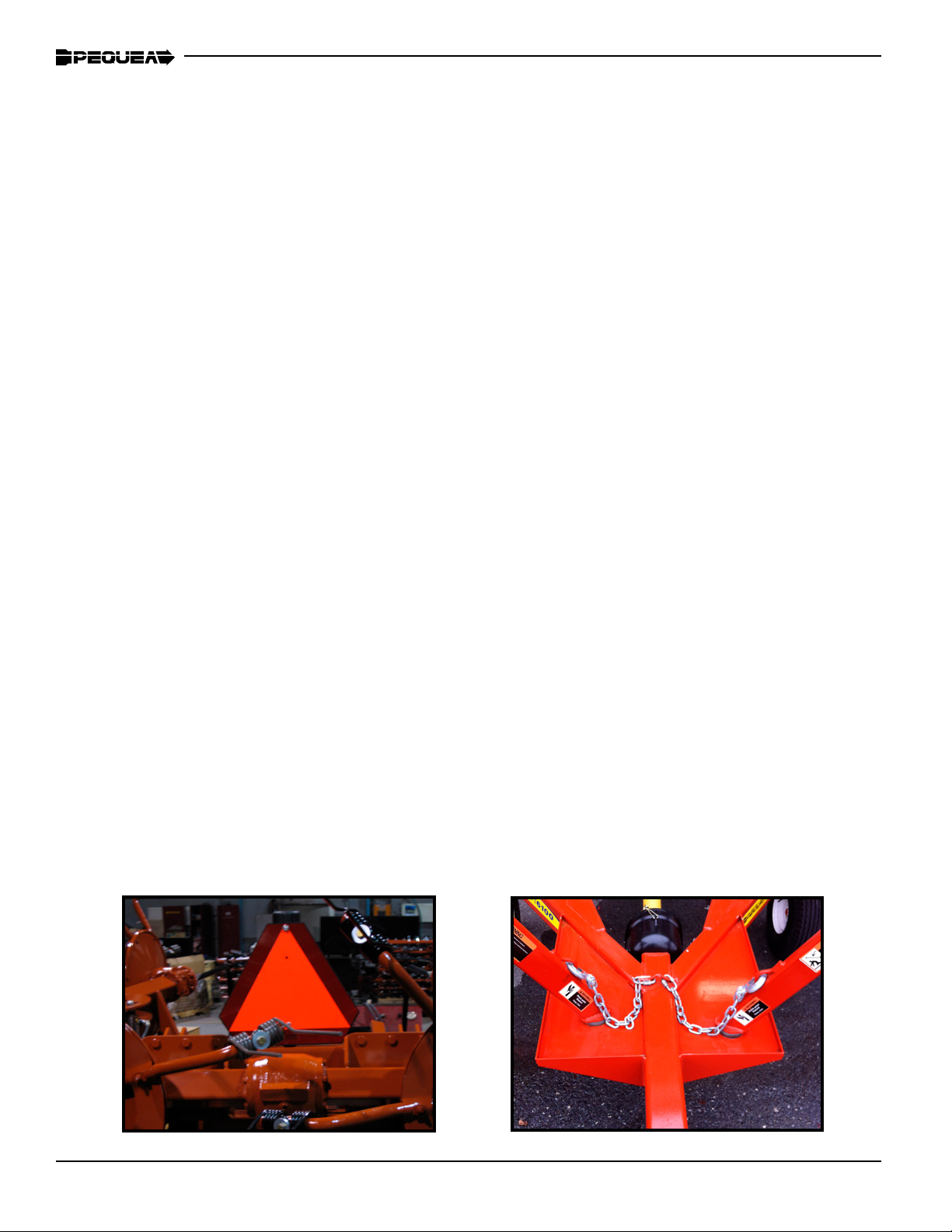
When transporting the machine on public roads use the proper reectors, lights, and slow
moving vehicle signs required by local government agencies. Pequea will not be liable for any
trac violations.
Be sure to check all fasteners before and after every use, this is especially important when
the tedder is new but is a good practice on any machinery with high vibration levels.
Be careful around hydraulic hoses and ttings. Never go near hydraulic leaks. High pressure
leaks can puncture skin and cause serious injury or death!
Do not attempt to fold the tedder until the machine is on at ground. Folding on uneven terrain
can cause the tedder to ip over.
Power Source Safety
Do not use a PTO shaft without a rotating shield in good working order. Make sure drive sys-
tem safety shields are in place on both the tractor and the tedder.
Do not overextend the PTO Shaft
PTO shield chains must be attached to the tractor and/or the tedder to keep the shield from
rotating.

4
SAFETY
Safety Decals and Reectors
Safety decals and reectors are for the safety of yourself and others, and must be heeded at all
times. If any decals are missing, faded, or damaged in any way, please contact your dealer for
replacements immediately. Shown below are some of the decals used on your tedder.

5
HITCHING
Attaching to the Tractor
Figure 1
Crank the jack up or down to align the tractor draw bar with the hitch.
The tedder hitch is bolted on and can be adjusted up or down to accommodate various drawbar
heights (Figure 1). Select a height that keeps the tedder chassis level when it is connected to
the tractor.
When attaching to the draw bar always use a draw bar pin with a safety clip to ensure that the
tedder doesn’t bounce o of the tractor.
After attaching the tedder, crank the jack down until all the weight rests on the tractor drawbar,
then remove the jack and place it in the transport position. (Figure 2)
Attach the PTO shaft to the tractor. Make sure the locking balls in the splined coupling are
operational and that the PTO shaft locks securely on the tractor output shaft. NOTE: Be sure to
push the PTO stand down against the tongue to avoid damage to the PTO shaft shielding.
The TT6100 is equipped with hydraulic cylinders to fold the machine for transport. The hoses
should be connected to a double acting valve at the rear of the tractor. The slotted holes on the
side of the tongue (Figure 1) are storage holes for the hoses
Connect the wiring plug from the tedder into the female plug end on the tractor. If your tractor
is not equipped with this plug you will need to have it installed by your dealer. Never travel on
public roads without proper lighting.
Figure 2

6
TRANSPORTING
Field Transport
Never allow any riders on the tractor or the tedder.
Remain fully aware of the width of the tedder in relation to objects you are passing.
Never travel at speeds of more than 12 MPH in the eld.
Road Transport
Adhere the suggestions for eld transport listed above.
Make sure the hands-free transport lock is latched in place properly (shown in Figure 13).
ALWAYS FOLLOW LOCAL TRAFFIC LAWS IN REGARDS TO THE TRANSPORTING OF FARM
EQUIPMENT. PEQUEA WILL NOT BE HELD LIABLE FOR FINES INCURRED DUE TO TRAF-
FIC VIOLATIONS.
Do not exceed 25 MPH on any public road. Excessive speeds combined with common road ob-
structions can cause failures.
Be sure the SMV (slow moving vehicle) Symbol is visible from the rear of the machine as shown
in Figure 3.
Keep a close eye on the tedder wings when transporting on the road or in the eld. A leaky valve
in the tractor’s hydraulic system will cause the tedder to slowly unfold. If this occurs, you will want
to disconnect the hydraulics before transporting. Figure 4 shows the wings supported properly for
transport and the safety chains attached.
Be sure to use the lights when traveling on the road at night.
Figure 3 Figure 4

7
FIELD SET UP
To lower the tedder into tedding position engage the hydraulics for the tilt cylinder rst to raise the
wings o of the chassis then engage the main hydraulics to unfold the wings. Be sure that nobody
is around the tedder or the tractor as the wings are lowering. The tines and arms can cause serious
injury to anybody that it comes into contact with. Make sure that the hitch is attached to the tractor
and the pin is installed when the wings are lowering. If the hitch is not properly attached to the trac-
tor, the weight of the rotors when it is unfolding could cause the hitch to whip up causing serious
personal injury or damage to equipment.
1-2”
NEVER RUN THE PTO WHILE THE TEDDER IS IN THE TRANS-
PORT POSITION! THIS CAN CAUSE DAMAGE TO THE JOINTS
AND ALSO POSES A PERSONAL INJURY HAZARD.
DO NOT ADJUST THE TEDDER UNLESS THE TRACTOR IS OFF AND THE PTO SHAFT
IS DISCONNECTED. ALWAYS ADJUST THE MACHINE BY YOURSELF. A SECOND
PERSON INCREASES THE CHANCE OF AN ACCIDENT.
The tine height adjustments can be made by turning the handle shown in Figure 6.
Turn the handle clockwise to raise the tine height.
Turn the handle counter clockwise to lower the tine height.
Generally, the tines should be around 1-2 inches from the ground for most crops. However, the
stubble length or crop moisture content can change where the optimum setting will be.
IT IS UP TO THE OPERATOR TO DETERMINE WHAT THE BEST POSITION SHOULD BE.
Figure 5 Figure 6

8
ADJUSTMENTS
Tine Pitch Adjustments
Figure 7 Figure 8
Figure 10Figure 9
The tine pitch (the angle of the tine in relation to the tine arm) can be adjust-
ed by reversing the eccentric spacer washer. The spacer position in Figure 7
will give the tine a less aggressive position as shown in Figure 8.
The spacer position shown in Figure 9 will give the tine a more aggressive
position as shown in Figure 10.
A more aggressive tine position will throw the hay higher.

9
ADJUSTMENTS
Axle Adjustments
The angle of the axles can be adjusted to raise or
lower the whole machine. This will allow you to tilt
the tedder forward more and get a more aggres-
sive tedding action. The tedders are set at the fac-
tory to run in the less aggressive position (shown
at right). To adjust to the higher position you will
need to pick the tedder up o the ground using
a hoist or a lift. With the tedder in the transport
mode, remove the 1/2” bolt, pull the axle forward
to meet the second hole, and reinsert bolt. Repeat
for all axles.
Figure 11
DO NOT BEGIN OPERATION UNTIL ALL OF THE SAFETY WARNINGS HAVE BEEN
READ AND UNDERSTOOD!
Once all of the adjustments and initial set up instructions have been followed and the proper
adjustments made, the tedder is ready to operate in the eld.
Connect the tedder PTO shaft to the tractor by pulling the spring collar back and sliding
the shaft yoke onto the 6 splined tractor PTO shaft. Slide the shaft forward until it stops and
then pull back slowly until the balls engage into the ball groove on the tractor shaft.
DO NOT RUN THE PTO UNLESS THE LOCKING BALLS ARE ENGAGED. THE SHAFT
COULD SLIDE OFF DURING OPERATION AND CAUSE SERIOUS INJURY OR DEATH.
The PTO speed should never exceed 540 rpm. Generally, 450 rpm and a 6 mph ground
speed is a comfortable operating setting. Crop conditions and eld conditions will ultimately
determine the settings for the tedder and the tractor.
GENERAL OPERATION

10
Folding for Transport
When tedding, the transport wheels can swivel and are spring loaded to support the weight of
the chassis. The springs will be compressed and the wheels locked in the straight position when
the tedder is folded up for transport. NOTE: Be sure to have the wheels relatively straight before
folding so the locks can engage properly! Figure 13 shows the transport lock properly engaged.
Do not transport the tedder until transport lock is latched in place as shown in Figure 14.
Transport lock
Figure 13
Figure 14
Transport Lock Engaged
Do not fold for transport unless the tedder is on even ground. Folding on uneven ground
can cause the tedder to tip over.

11
LUBRICATION AND MAINTENANCE
NEVER PERFORM ROUTINE MAINTENANCE, REPAIRS OR INSPECTIONS ON ANY
PIECE OF EQUIPMENT UNLESS THE TRACTOR IS SHUT OFF AND DISCONNECTED
FROM THE MACHINE.
IT IS ALWAYS BETTER TO WORK WITH ANOTHER PERSON WHEN MAINTAINING OR
SERVICING A PIECE OF EQUIPMENT. ACCIDENTS CAN BE PREVENTED AND HELP
CAN BE ATTAINED EASIER WHEN ANOTHER PERSON IS AVAILABLE TO HELP.
Gearbox Lubrication
The oil in the center gearbox should be drained out and replaced every year. When relling the
gearbox, remove the ll plug and ll up to the ll hole using 64oz of 80W-90 gear oil. Check the
oil level periodically throughout the season to insure that it remains full at all times.
Be sure to properly dispose of any used oil or grease! Do not pour directly onto the ground!
Figure 15
OIL FILL PLUG
OIL DRAIN PLUG
CHECK PLUG

12
LUBRICATION AND MAINTENANCE
Figure 16
The rotor gearboxes (Figure 16) have been packed
with grease at the factory and should not need to be
maintained. However, they should be checked before
each season to make sure the gears are still coated
with a lm of grease. If additional grease is needed,
use several ounces of NLGI #2 gear grease.
All of the pivot points have a grease
tting and a bronze bushing. This
should always be visibly wet with
grease. Grease as needed.
General Lubrication
When a grease point has specic hourly frequency, 1 full pump should be sucient lubrica-
tion. Always use a grease that is rated for high temperatures commonly found in a bearing.
The grease in the rotor gearboxes can seep out as the spindle exes. Do not be alarmed,
this is normal. The seal is exible, so when the spindle exes it can cause a small gap which
allows oil to seep out between the seal and the spindle assembly.
The cylinder nut should always be
visually wet with grease. Grease as
needed.
Figure 17
Figure 18

13
LUBRICATION AND MAINTENANCE
As is the case with any piece of new equipment, periodically check for loose
bolts and nuts. Paint and parts settling after the initial vibrations are common
and can cause bolts or nuts to loosen. Check the following parts frequently:
•Lug Bolts
•Tines & Tine Arms
• Guards
•Hydraulic Fittings
•All Fasteners
The plastic PTO shielding should be
lubricated at all times. If the shield
feels tight when it is extended and re-
tracted then lubricate as necessary.
The radial pin clutch and the center
cross in the PTO yokes should be
greased every 8 hours.
PTO Shaft Lubrication

14
ELECTRICAL
Your tedder is equipped with lights to be used when transporting on public roads. Make sure the wir-
ing and the lights are kept fully functional at all times. Shown below is the wiring diagram for the 7-pin
connector plug and the color code used for all Pequea equipment and trailers. The drawing is shown
looking at the back side of the plug insert. NOTE: this is showing the full wiring schematic for this type
of plug. The tedder only uses four of these wires; #1, #3, #5, & #6.
1
2
3
4
7
6
5
Position Function Wire Color
1 Ground White
2 Spare Circuit
3Left Turn Signal Yellow
4Auxiliary Red
5Right Turn Signal Green
6 Running Lights Brown
7 Electric Brakes Black
Wiring Schematic for 7-Pin Wiring Plug

15
TECHNICAL
Replacing the Flotation Springs
The otation springs are located inside the mounting stem of the transport wheels. (The large wheels
on the chassis). These wheels are also designed to carry the weight of the chassis when the tedder is
in the working mode. The springs may need to be replaced periodically if they become weakened and
no longer provide the desired amount of assistance. If so, follow the directions below to replace.
•Lift the tedder with a hoist or a lift to take all the weight o of the transport wheels.
• Use two clamps to hold the cap onto the spring tube.
•Remove the bolts from the cap and slowly release the clamps until the spring is fully extended
and there is no more force on the clamp.
Replace the spring and put the cap back on.
FAILURE TO FOLLOW THESE INSTRUCTIONS COULD RESULT IN PERSONAL INJURY AS A
RESULT OF THE CAP BEING LAUNCHED BY THE SPRING WHEN THE BOLTS ARE BEING RE-
MOVED.
IMPORTANT: Raise tedder with lift or hoist and
apply clamping force to the cap while removing
the bolts.

16
Timing the rotors
The rotor gears are set at the factory and should not need to be serviced or retimed. However, when
replacing a hexagonal drive shaft or gearbox it is necessary to time the rotors. The gures below
show correctly timed rotors and incorrectly timed rotors.
Tools Needed:
-90° Snap Ring Pliers
-Prybar
-Hammer
-Punch
-9/16” Wrench or impact
Figure 23: Rotors Timed Correctly
Figure 23: Rotors Not Timed Correctly
If something does happen that causes the gears to come out of time you can follow the steps below to
retime:
First, fold the arms of the tedder up into transport mode. While pushing the outer wing towards the
inside as much possible, use the 90° snap ring pliers to remove the snap ring from the hex shaft. Re-
move the bushing from the hex shaft and place the two parts to the side.

17
Use the prybar to slowly push the hex shaft
down towards the outer end of the wing. The
hex shaft only needs to be moved about 1.25” in
order to retime the rotor. While pushing the hex
shaft down, continuously turn the rotor back and
forth. As soon as the outer wing rotor can spin
independently without the inner wing rotor, stop
pushing hex shaft. Avoid pushing the hex shaft
more than 1.5” towards the outside. This will
make it more dicult to put back in place when
the rotor is retimed.
Rotate the inner wing rotor until the prole on
the nger joint is as shown, with a at edge
on the top and bottom sides. This is important
because the outer hex shaft will have to t this
prole before being reinserted back through.
Remove the guard cradle from the outside wing.
This is necessary to see what the prole of the
outer hex shaft is.

18
Before re-inserting the hex shaft back through, the following two conditions must be met:
1) The spacing between the tines must be equal so that the tin from the outer wings ts in the center
of the tines from the inner wing.
2) The prole of the outer hex shaft must be at, so that it will t back through the nger joint.
Turn the outer rotor until both conditions are met. When the rotor appears to be timed correctly, use a
punch to push the hex shaft back to the original position. Do not force the hex shaft back through if it
is tight. This may mean the prole of the hex shaft does not match the prole of the nger joint. After
the hex shaft is through, put the bushing and snap ring back on the hex shaft and the guard cradle
back in position.
Additional Notes: If multiple rotors are out of time, it is always best to start on the inside and work
towards the outside. When one of the two center rotors are out of time, the hex shaft must be pushed
through until it goes through the input pinion of the rotory gearbox. If this is the case, use a punch to
slowly work the hex shaft down while turning one of the rotors back and forth. As soon as the rotors
can move independently, do not push the hex shaft down any further. After that, the process is the
same as in retiming the wing rotors.
12
Table of contents
Other PEQUEA Farm Equipment manuals