List of tables
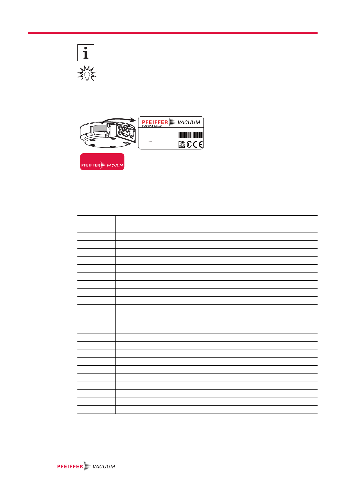
Tbl. 1: Stickers on the product 8
Tbl. 2: Abbreviations used in this document 8
Tbl. 3: Permissible ambient conditions 12
Tbl. 4: Features of the device variant 14
Tbl. 5: Delivered drive power depending on the supplied mains voltage 14
Tbl. 6: Connection description of the electronic drive unit 15
Tbl. 7: Terminal lay-out of "Profibus" M12 connection 18
Tbl. 8: Terminal lay-out of 26-pin "remote" connection 19
Tbl. 9: Terminal lay-out of the power supply connector 20
Tbl. 10: Overview of the Profibus modules 21
Tbl. 11: Definitions of Profibus parameterization data 22
Tbl. 12: Profibus module designation in terms of parameterization data 22
Tbl. 13: Output and input data ("PPO1") 22
Tbl. 14: Request (output data "PPO1") 22
Tbl. 15: Response (input data "PPO1") 22
Tbl. 16: Error numbers (response "PPO1") 23
Tbl. 17: Control word/status word ("PPO1") 23
Tbl. 18: Output and input data ("PPO3") 23
Tbl. 19: Output and input data ("control/status word") 24
Tbl. 20: Output and input data ("control/status byte") 24
Tbl. 21: Control word/status word ("control/status byte") 24
Tbl. 22: Profibus: Expanded diagnostics data 25
Tbl. 23: Explanation and meaning of the parameters 27
Tbl. 24: Control commands 30
Tbl. 25: Status requests 31
Tbl. 26: Reference value inputs 32
Tbl. 27: Parameters for Profibus connection 32
Tbl. 28: Parameters for control unit functions 33
Tbl. 29: Digital outputs and relays 34
Tbl. 30: Digital inputs 34
Tbl. 31: Analog output 35
Tbl. 32: Analog input 35
Tbl. 33: Accessory connections 35
Tbl. 34: Parameter [P:060] 36
Tbl. 35: Parameter [P:061] 36
Tbl. 36: Characteristic nominal rotation speeds of the turbopumps 40
Tbl. 37: Backing pump operating modes 40
Tbl. 38: DI1 (release venting) / Pin 2 42
Tbl. 39: DI motor pump/pin 3 43
Tbl. 40: DI pumping station / Pin 4 43
Tbl. 41: DI standby/pin 5 43
Tbl. 42: DI2 (heater)/pin 6 43
Tbl. 43: DI3 (sealing gas)/pin 10 43
Tbl. 44: DI malfunction acknowledgment/pin 13 43
Tbl. 45: DI remote priority/pin 14 43
Tbl. 46: RS-485 interface, features 45
Tbl. 47: Behavior and meaning of the LEDs on the electronic drive unit 46
Tbl. 48: Behavior and meaning of the Profibus LED 46
Tbl. 49: Error messages of the electronic drive unit 49
Tbl. 50: Warning messages of the electronic drive unit 50
Tbl. 51: Warning and malfunction messages 50
List of tables
5/56