manuals.online logo
Brands
  1. Home
  2. •
  3. Brands
  4. •
  5. Philips
  6. •
  7. Controllers
  8. •
  9. Philips dynalite DDC116 User manual

Philips dynalite DDC116 User manual

DDC116
Signal Dimmer
Controller
RJ45
1.69 in (43 mm)
4.40 in (112 mm)
4.33 in (110 mm)
3.62 in (92 mm)
7.87 in
(200 mm)
1.14 in (29 mm)
0.71 in
(18 mm)
1 A B1
Installation Instructions
Instructions d’installation
Instrucciones de instalación
113° F (45° C)
32° F (0° C)
≤90%
Devices must be installed by a
quali ed electrician in accordance with
all national and local electrical and
construction codes and regulations.
Les appareils doivent être installés par un
électricien diplômé conformément à tous les
codes et réglementations électriques et de
construction nationaux et locaux.
Los dispositivos deben ser instalados por un
electricista cali cado y cumpliendo todas
las normas y regulaciones, tanto nacionales
como locales, sobre instalaciones eléctricas
y obras.
2 in (51 mm)
UL 2043 Plenum-rated Chicago Plenum-rated
3
2
*Controlled receptacle (Plug load)
Output Ratings
General Use*
Load Type
20 A, 277 V
16 A, 277 V
6 A, 120 V
3 A, 140 V
2.6 A, 277 V
Electronic Driver
Pilot Duty
DALI
Broadcast
Control Channel Ratings
0-10 V
≤ 40
Guaranteed 100 mA
Maximum 250 mA
Insulation: basic
Sink 100 mA
Source 100 mA
Load
type
1-10 V
DSI/DALI
16 FLA (1 HP), 120 V
14.5 FLA (2 1/
2
HP), 240 V
14.1 FLA (3 HP), 277 V
Motor
M
12 V 200 mA
0-10 V/DALI
Class 2, suitable for wiring as Class 1.
RS-485
µP
L out
L N
DA+
+ -
DA-
100-277 V 20 A
1 – D+
2 – D-
3 – SHIELD
4 – + 12 V
5 – + 12 V
6 – SHIELD
7 – GND
8 – GND
AUX/
UL924
GND
D+
D-
+12V
0-10 V/DALI
1 8
1 8
RS-485 DyNet/DMX512 Rx
DMX
Terminator
UL924
Input
Class 2
4
IEC Overvoltage Category III
To avoid electrical overload, total external connected load must not exceed output rating.
IEC Polution Degree II
DDC116
*0-10 V Dimming Common from luminaire
may be pink or as otherwise permitted
per section 410.69 of the 2020 NEC.
BLACK
GREEN
RED
PINK*
WHITE
= LINE
= EARTH
= NEUTRAL
= SWITCHED LINE
= 0-10 V+ / DA+
= 0-10 V- / DA-
BLACK
GREEN
WHITE
RED
VIOLET
PINK
12 AWG (2.5mm²)
18 AWG (0.75mm2)
0-10 V+ / DA+
0-10 V- / DA-
VIOLET
0-10 V / DALI
DRIVER
2
6
7
7
5
From previous network device
To next network device
RS-485 DyNet / DMX512 and UL924
GND AUX/UL924
< 65 ft
(20 m) 0.2-1.5mm
2
24-16 AWG
RS-485 DyNet / DMX512
1 Orange-white D+
2 Orange D-
3 Green-white SHIELD
4 Blue + V
5 Blue-white + V
6 Green SHIELD
7 Brown-white GND
8 Brown GND
AUX/
UL924
Service
Switch
Service
LED
GND
D+
D -
+12V
GND
Service
Switch
Service
LED
In/Out
RJ45
In/Out
A
B
RS-485 DyNet
DMX512
RS-485 DyNet
DMX512
3
AUX/UL924 default is Normally Closed (Open = Active).
Pin numbering and color in accordance with ANSI/TIA/EIA-568 scheme T568B.
For DMX512, add a 120 Ohm, 0.5 W termination resistor across D+ and D- on the last DMX512 device.
Please remove jumper wire between GND and AUX/UL924 terminals if connecting to Emergency or other system.
AZZ 580 1223 R05
© 2023 Signify Holding. All rights reserved. Specications are subject to change
without notice. No representation or warranty as to the accuracy or completeness
of the information included herein is given and any liability for any action in
reliance thereon is disclaimed. Philips and the Philips Shield Emblem are registered
trademarks of Koninklijke Philips N.V. All other trademarks are owned by Signify
Holding or their respective owners.
www.dynalite.com
IMPORTANT SAFEGUARDS
When using electrical equipment, basic safety precautions should always be
followed including the following:
READ AND FOLLOW ALL
SAFETY INSTRUCTIONS
a) Do not use outdoors
b) Do not use this equipment for other than the intended use.
SAVE THESE INSTRUCTIONS
Caution – 0-10 V/DALI wires may be either Class 1 or Class 2 depending on the installation and ratings of the connected devices – Class 1 applications are not
SELV and should never be considered touch safe. Basic insulation or higher is required between 0-10 V/DALI wires and mains cabling as per local electrical codes.
Caution – Any modications not approved by the manufacturer of this device could void the user’s authority to operate this device.
FCC and RSS-210 of IC (Industry Canada) Rules – This equipment has been tested and found to comply with the limits for a Class B digital device, pursuant
to part 15 of the FCC Rules and pursuant to RSS210 of the IC Rules. These limits are designed to provide reasonable protection against harmful interference
in a residential installation. This equipment generates, uses, and can radiate radio frequency energy and, if not installed and used in accordance with the
instructions, may cause harmful interference to radio communications. However, there is no guarantee that interference will not occur in a particular installation.
If this equipment does cause harmful interference to radio or television reception, which can be determined by turning the equipment o and on, the user is
encouraged to try to correct the interference by one or more of the following measures: Reorient or relocate the receiving antenna. Increase the separation
between the equipment and receiver. Connect the equipment into an outlet on a circuit dierent from that to which the receiver is connected. Consult the dealer
or an experienced radio/TV technician for help. Any modications not approved by the manufacturer of this device could void the user’s authority to operate this
device.
This Class B digital apparatus complies with Canadian ICES-003: CAN ICES-3(B)/NMB-3(B). Cet appareil numerique de la Classe B est conforme a la norme
NMB-003 du Canada: CAN ICES-3(B)/NMB-3(B).
8 9
Service Switch
1 push – Network ID
3 pushes – Channel to 100%
4 pushes – Test Mode (lights ash for 5 minutes):
• Push and hold 2 seconds – toggle control type between 0-10 V (fast LED blink) and
• DALI Broadcast (slow LED blink).
• 2 pushes – Save control type.
• 1 push – Exit Test Mode.
Push and hold 4 seconds – Enter Program Mode (LED blinks):
• 1 to 6 pushes – cycle channel number (LED blinks on each push).
Channel 1 = Zone 1 lighting (default)
Channel 2 = Zone 2 lighting
Channel 3 = Zone 3 lighting
Channel 4 = Zone 4 lighting (primary daylight zone)
Channel 5 = Zone 5 lighting (secondary daylight zone, 20% brighter)
Channel 6 = Plug load
• Wait for 4 seconds – (LED blinks).
• 2 pushes – Save channel number and exit Program Mode.
• Program Mode times out after 60 seconds of inactivity, discarding changes.
Other Philips Controllers manuals

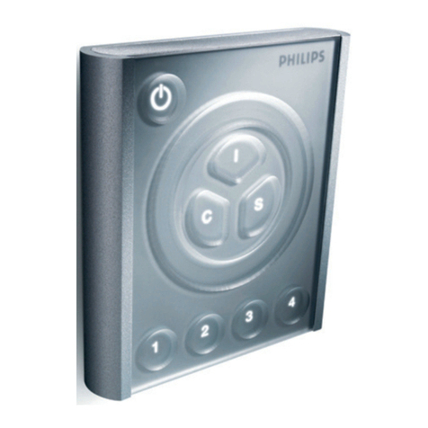
Philips Dynalite DMRC210 User manual

Philips

Philips Dynalite DMRC210 User manual

Philips Vaya Touch Controller User manual

Philips

Philips Vaya Touch Controller User manual

Philips Dynalite Revolution DR2PE User manual

Philips

Philips Dynalite Revolution DR2PE User manual

Philips 9890 000 0268 Series User manual

Philips

Philips 9890 000 0268 Series User manual

Philips Dynalite DDBC516FR User manual

Philips

Philips Dynalite DDBC516FR User manual

Philips iPlayer3 User manual

Philips

Philips iPlayer3 User manual

Philips AntumbraButton User manual

Philips

Philips AntumbraButton User manual

Philips TDA8002C User manual

Philips

Philips TDA8002C User manual

Philips Dynalite DDBC300-DALI User manual

Philips

Philips Dynalite DDBC300-DALI User manual

Philips Dynalite DMAL120F User manual

Philips

Philips Dynalite DMAL120F User manual

Philips Dynalite DMC-GRMS-UL User manual

Philips

Philips Dynalite DMC-GRMS-UL User manual

Philips CoralCare User manual

Philips

Philips CoralCare User manual

Philips Dynalite DLE1205 User manual

Philips

Philips Dynalite DLE1205 User manual

Philips DYNALITE DDRC1220FR-GL User manual

Philips

Philips DYNALITE DDRC1220FR-GL User manual

Philips Dynalite DDLE801 User manual

Philips

Philips Dynalite DDLE801 User manual

Philips MSX VU 0005 User manual

Philips

Philips MSX VU 0005 User manual

Philips dynalite DMRC210-RJ-DA User manual

Philips

Philips dynalite DMRC210-RJ-DA User manual

Philips dynalite DALI DDBC120-DALI User manual

Philips

Philips dynalite DALI DDBC120-DALI User manual

Philips Dynalite DBC1205 User manual

Philips

Philips Dynalite DBC1205 User manual

Philips Dynalite DMRC210DA-RJ12 User manual

Philips

Philips Dynalite DMRC210DA-RJ12 User manual

Philips ISP1362 User manual

Philips

Philips ISP1362 User manual

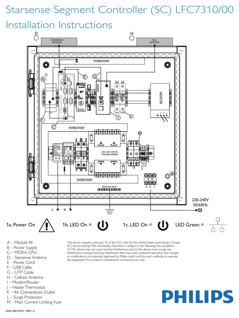
Philips LFC7310 User manual

Philips

Philips LFC7310 User manual

Philips dynalite DDBC120-DALI User manual

Philips

Philips dynalite DDBC120-DALI User manual

Philips dynalite DBC1210 User manual

Philips

Philips dynalite DBC1210 User manual

Popular Controllers manuals by other brands

Timotion TBB5 user manual

Timotion

Timotion TBB5 user manual

BRAX BRAX installation instructions

BRAX

BRAX BRAX installation instructions

SENSIRION SFC6 Series manual

SENSIRION

SENSIRION SFC6 Series manual

HIRSCH AEB8 user manual

HIRSCH

HIRSCH AEB8 user manual

2VV SC-C quick guide

2VV

2VV SC-C quick guide

Vishay ESTAmat PFC-N operating instructions

Vishay

Vishay ESTAmat PFC-N operating instructions

Hewalex OPTI-TEMP Installation and maintenance guide

Hewalex

Hewalex OPTI-TEMP Installation and maintenance guide

ABB Relion 670 series Product guide

ABB

ABB Relion 670 series Product guide

Berker 7531 10 1 Series Operating and assembly instructions

Berker

Berker 7531 10 1 Series Operating and assembly instructions

Luxul XWS-2610 Quick install guide

Luxul

Luxul XWS-2610 Quick install guide

BWT Manager Connect Duo instruction manual

BWT

BWT Manager Connect Duo instruction manual

Huawei SmartACU2000D Series quick guide

Huawei

Huawei SmartACU2000D Series quick guide

CIMCON Lighting iSLC3100-7P-C Installation and Commissioning Procedure

CIMCON Lighting

CIMCON Lighting iSLC3100-7P-C Installation and Commissioning Procedure

White Rodgers 668-430 user manual

White Rodgers

White Rodgers 668-430 user manual

Bernard Controls Gamme FQ Series INSTRUCTIONS FOR START-UP

Bernard Controls

Bernard Controls Gamme FQ Series INSTRUCTIONS FOR START-UP

Raven SCS 460 installation manual

Raven

Raven SCS 460 installation manual

Jetter JC-440 installation manual

Jetter

Jetter JC-440 installation manual

rotork CMA Series Installation & maintenance instructions

rotork

rotork CMA Series Installation & maintenance instructions

manuals.online logo
manuals.online logoBrands
  • About & Mission
  • Contact us
  • Privacy Policy
  • Terms and Conditions

Copyright 2025 Manuals.Online. All Rights Reserved.