manuals.online logo
Brands
  1. Home
  2. •
  3. Brands
  4. •
  5. Philips
  6. •
  7. Lantern
  8. •
  9. Philips TMFIC Series User manual

Philips TMFIC Series User manual

Philips Lighting North America Corporation
200 Franklin Square Drive
Somerset, NJ 08873, USA
Phone: 855-486-2216
www.philips.com/luminaires
Philips Lighting Canada Ltd.
281 Hillmount Road,
Markham, ON, Canada L6C 2S3
Phone: 800-668-9008
www.philips.com/luminaires
9140053342 February 2016
TMFIC/ZMFIC Series
200W-450W Emergency
Luminaire
INSTALLATION AND
OPERATING
INSTRUCTIONS
IMPORTANT
SAFEGUARDS
When using electrical equipment, basic safety
precautions should always be followed, including
the following:
READ AND FOLLOW ALL
SAFETY INSTRUCTIONS
All servicing should be performed by qualified
personnel only.
Equipment should be mounted in locations and at
heights where it will not be readily subjected to
tampering by unauthorized personnel.
The use of accessory equipment not recommended
by the manufacturer may cause an unsafe condition.
Do not use this equipment for other than intended
use.
Do not use outdoors.
Do not let supply cords touch hot surfaces.
Do not mount near gas or electric heaters.
CAUTION: Halogen cycle lamp(s) are used in
this equipment. To avoid shattering: Do not
operate lamp in excess of rated voltage, protect
lamp against abrasion and scratches and against
liquids when lamp is operating, dispose of lamp
with care.
Halogen cycle lamps operate at high temperatures.
Do not store or place flammable materials near
lamp.
CAUTION: “To avoid electrical overload, total
connected lamp load (factory and field installed)
should not exceed output rating”.
SAVE THESE
INSTRUCTIONS
WARNING –Shut off AC power to branch
circuits to which units will be connected. All
wiring should be per N.E.C. Articles 501-4(b)
and local codes.
To maintain warranty, equipment with batteries
must be installed or placed on charge within
prescribed period after shipment.
Philips Lighting North America Corporation
200 Franklin Square Drive
Somerset, NJ 08873, USA
Phone: 855-486-2216
www.philips.com/luminaires
Philips Lighting Canada Ltd.
281 Hillmount Road,
Markham, ON, Canada L6C 2S3
Phone: 800-668-9008
www.philips.com/luminaires
9140053342 February 2016
GENERAL INSTRUCTIONS
Direct Wall Mount Installation
1) Begin the installation process by securing
the unit less battery. Three slotted vertical
keyway knockouts in the housing (see
Figure 1) are to be used to attach the
housing to independent anchor supports.
Use three ¼” toggle bolts (supplied by
others) to secure the unit to drywall. If
mounting to hollow concrete masonry, a
minimum of two toggle bolts must be used.
When using wall recessed wiring, The
slotted, circular keyways can be used to
secure the housing to a standard junction
box for wiring purposes only. Run the wires
through center hole of housing in
preparation for unit wiring. For surface
conduit wiring, there are a total of six
knockouts which can be used for service
entrance and exit.
Figure 1
OPTIONAL MOUNTING SHELF FOR
COLUMN, POLE OR I-BEAM
1) If the unit is to be mounted to poles,
columns or I-Beams, use the optional
mounting shelf kit and strapping kit (ordered
separately).
2) If mounting shelf is to be used for wall
mounting, there are four (4) slotted vertical
keyways (see Figure 2) available. Use ¼”
toggle bolts (supplied by others) for
installation.
Figure 2
3) Once mounting shelf is installed, the unit is
ready for installation.
4) Place unit on shelf less batteries and secure
with three (3) securing screws (provided
with mounting shelf) to shelf threaded
inserts.
INSTALLING BATTERIES
1. Units ship without batteries installed. Unit
batteries are shipped separately. Battery
wiring harnesses are already connected to
PCB assembly. Connection of harness to
batteries is required.
2. Install and wire batteries as appropriate.
(See Page 8 for battery configurations)
3. Tighten straps to secure batteries inside unit.
Philips Lighting North America Corporation
200 Franklin Square Drive
Somerset, NJ 08873, USA
Phone: 855-486-2216
www.philips.com/luminaires
Philips Lighting Canada Ltd.
281 Hillmount Road,
Markham, ON, Canada L6C 2S3
Phone: 800-668-9008
www.philips.com/luminaires
9140053342 February 2016
AC SERVICE
HOOKUP INSTRUCTIONS
Standard Units:
Connect AC service to unit terminal block.
The unit is pre-wired to accept 120 or 277
VAC. Insert AC service leads and ground
wire to appropriately labeled terminal(s).
Tighten.
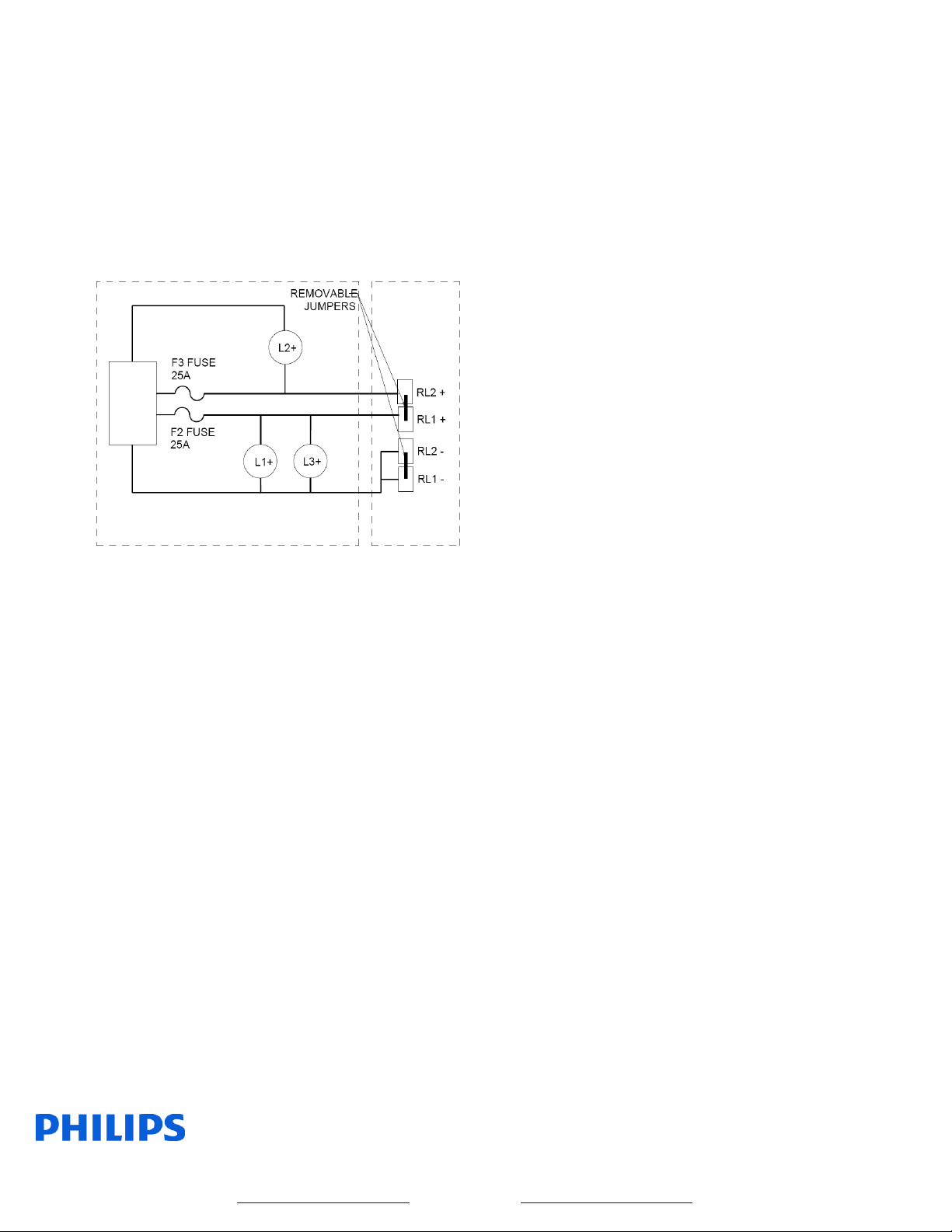
REMOTE LAMP CONNECTION
1. A terminal block for the remote lamp loads
is provided for easy installation. Two
terminals are available for DC+ and DC-
each. Units ship from the factory with load
connection jumpers installed on both DC+
and DC-. This parallels the load among the
unit RL1+ and RL2+ output load fuses.
Using the jumpers ensures that the total load
of the unit is evenly distributed.
2. REMOTE LOADS WITH LOAD
CONNECTION JUMPERS INSTALLED
(SMALLER REMOTE LOAD REQUIREMENTS)
1. When using the jumpers, simply subtract the
internal lamp total wattage from the unit
total wattage and the remainder is the
available total remote load capacity.
Balancing of RL1 and RL2 is not required as
the jumpers perform the remote load
balancing.
2. When figuring total load, include the
wattage of the internal lamps if applicable
and do not exceed unit total wattage
capability.
3. EXAMPLE:
A 200 watt unit with three (3) 12 watt
lamps connected has 164 watts of remote
load capability.
REMOTE LOADS REQUIRING
SEPARATE FUSING
(LARGER REMOTE LOAD REQUIREMENTS)
1. When it is necessary to independently fuse
each set of remote lamp loads, removal of
the load connection jumpers is required.
2. Removal of the load connection jumpers is
accomplished unscrewing and removing the
jumper itself.
3. The terminals are marked RL1 DC+, RL2
DC+, RL1 DC- and RL2 DC-. The terminal
blocks are capable of accepting up to #6
wire.
Balancing of the remote lamp loads among
RL1 and RL2 is now a consideration and
must be planned ahead of time.
Philips Lighting North America Corporation
200 Franklin Square Drive
Somerset, NJ 08873, USA
Phone: 855-486-2216
www.philips.com/luminaires
Philips Lighting Canada Ltd.
281 Hillmount Road,
Markham, ON, Canada L6C 2S3
Phone: 800-668-9008
www.philips.com/luminaires
9140053342 February 2016
Determination of allowable RL1 and RL2
maximum capacity depends on whether the
unit is configured as a two or three internal
head unit as the remote load PCB fuses are
shared with the internal lamps.
The schematic below illustrates the PCB
load routing of the unit where L1+, L2+ and
L3+ represent internal lamp loads and RL1+
and RL2+ are the remote lamp loads:
4. Determining allowable remote lamp loads
for RL1 and RL2:
- For two head units, subtract twice the lamp
wattage rating from the unit total available
power. Equally divide the remaining
capacity between RL1 and RL2.
- For three head units, internal lamp 1 and
internal lamp 3 are on the RL1 fused circuit.
Internal lamp 2 is connected to the RL2
fused circuit.
For RL1 circuit, subtract twice the internal
lamp rating from half the unit wattage and
the remainder is the available remote load
capacity.
For RL2 circuit, subtract one internal lamp
wattage from half the unit wattage and the
remainder is the RL2 remote capacity.
Example:
A 300 watt unit is configured with 3 internal
12 watt heads. The total available wattages
for RL1 and RL2 are calculated as follows:
RL1 Max Watts = (Unit Wattage / 2) –(2 * Internal
Lamp Wattage)
= (300/2) - (2*12)
= 150 –24
= 126 (Watts)
RL2 Max Watts = (Unit Wattage / 2) –(1 * Internal
Lamp Wattage) = (300/2) –(1*12)
= 150 –12
= 138 (Watts)
Ensure total unit load (including internal
lamps) does not exceed unit rating including
internal lamp loads.
COMPLETING UNIT INSTALLATION
1. Adjust head(s) to illuminate desired area(s).
2. Close cover and latch. Ensure electrical
wires and membrane switch cable remain
inside unit and that the cover does not pinch
wires when closed. Hand tighten the two
thumb screws to finalize cover closure.
Philips Lighting North America Corporation
200 Franklin Square Drive
Somerset, NJ 08873, USA
Phone: 855-486-2216
www.philips.com/luminaires
Philips Lighting Canada Ltd.
281 Hillmount Road,
Markham, ON, Canada L6C 2S3
Phone: 800-668-9008
www.philips.com/luminaires
9140053342 February 2016
Self Diagnostic System Operation –Emergency Light or EXIT Sign Products
Normal Power Up Sequence
At power up the red and green LED indicators will alternately flash for one to two seconds. Next the product will execute
a “Power Up Quick Test” causing the green LED indicator to flash rapidly. If any faults are detected during the “Power Up
Quick Test” these will be evident by a flashing red LED indicator. If the audible diagnostic option has been ordered, the
flashing red LED will be accompanied by a simultaneous beeping tone. (Note: A continuous rapid alternating Red/Green
flash with rapid beeping tone indicates 277V applied to 120V input lead. TURN OFF POWER IMMEDIATELY!)
Emergency Operation
Emergency operation occurs when AC power fails. The product remains in emergency operation until AC power is
restored or battery capacity is depleted. During emergency operation both red and green LED indicators are disabled.
User Interface
Green LED indicator
Slow Flash/Continuous ON = AC power present; normal operating condition
Rapid Flash = product performing an automatic or manually initiated diagnostic test
Red LED indicator
Single Flash = battery fault
Two Flashes = lamp failure (light bar failure –EXIT signs)
Three Flashes = charger fault
Four Flashes = transfer fault
(If more than one fault condition is present simultaneously, the red LED will flash the indication pattern for each
fault independently then repeat the cycle.)
Pushbutton Test Switch
Long Press (longer than 0.5sec) transfers product to emergency operation during time the button is
pressed.
Short Press initiates self diagnostic activities as follows:
One Press cancels diagnostic test presently running.
Two Presses starts a one minute diagnostic test.
Three Presses starts a 90 minute diagnostic test.
Four Presses conducts a lamp load calibration (emergency light products only).
Seven Presses initiates a system reset.
(Note: the microprocessor will allow up to seven, one minute diagnostic tests within the first 24 hours of
operation. Allow 24 hours of charging before performing any long duration testing.)
Buzzer (optional)–Sounds in unison with the flashing red LED if a fault condition is present. Buzzer may be
silenced for up to 196 hours by a short press of either the test switch or the optional IR remote control device
“silence” button. Correcting fault condition will cancel fault notification. Lamp failure indication requires a
manually activated diagnostic test after lamp replacement to cancel notification.
IR Remote Control (optional)- is a hand held device that allows remote activation of diagnostic testing and
silencing of the optional buzzer during fault conditions.
Philips Lighting North America Corporation
200 Franklin Square Drive
Somerset, NJ 08873, USA
Phone: 855-486-2216
www.philips.com/luminaires
Philips Lighting Canada Ltd.
281 Hillmount Road,
Markham, ON, Canada L6C 2S3
Phone: 800-668-9008
www.philips.com/luminaires
9140053342 February 2016
Philips Lighting North America Corporation
200 Franklin Square Drive
Somerset, NJ 08873, USA
Phone: 855-486-2216
www.philips.com/luminaires
Philips Lighting Canada Ltd.
281 Hillmount Road,
Markham, ON, Canada L6C 2S3
Phone: 800-668-9008
www.philips.com/luminaires
9140053342 February 2016
BATTERY HOOKUP DIAGRAMS
12V 200W
12V 250W
12V 300W
24V 300W
12V 450W
24V 450W

This manual suits for next models

1

Other Philips Lantern manuals

Philips Ledinaire Waterproof WT050C User guide

Philips

Philips Ledinaire Waterproof WT050C User guide

Philips BGP300 User manual

Philips

Philips BGP300 User manual

Philips Selecon PLSTUPNL-03 Instruction Manual

Philips

Philips Selecon PLSTUPNL-03 Instruction Manual

Philips GSA ST321T User manual

Philips

Philips GSA ST321T User manual

Philips CMFIC Series User manual

Philips

Philips CMFIC Series User manual

Philips CoreLine BN120C Series User manual

Philips

Philips CoreLine BN120C Series User manual

Philips Stylid Evo Compact ST770B User manual

Philips

Philips Stylid Evo Compact ST770B User manual

Philips Luma gen 2 Series User manual

Philips

Philips Luma gen 2 Series User manual

Philips Innergize HB945 User manual

Philips

Philips Innergize HB945 User manual

Philips LifeLight User manual

Philips

Philips LifeLight User manual

Philips series User manual

Philips

Philips series User manual

Philips LED Luminaires User manual

Philips

Philips LED Luminaires User manual

Philips ClearScape LED Series User manual

Philips

Philips ClearScape LED Series User manual

Philips Selecon PLFR1MKII-03 Instruction Manual

Philips

Philips Selecon PLFR1MKII-03 Instruction Manual

Philips CoreLine Waterproof WT120C G2 EL MDU User manual

Philips

Philips CoreLine Waterproof WT120C G2 EL MDU User manual

Philips SmartBright BY240P User guide

Philips

Philips SmartBright BY240P User guide

Philips 16942-87-16 User manual

Philips

Philips 16942-87-16 User manual

Philips UrbanSpark BDP301 Use and care manual

Philips

Philips UrbanSpark BDP301 Use and care manual

Philips GentleSpace Gen3 User manual

Philips

Philips GentleSpace Gen3 User manual

Philips GSA ST321Y User manual

Philips

Philips GSA ST321Y User manual

Philips WT202W User manual

Philips

Philips WT202W User manual

Philips PrimeSet LDM524 User manual

Philips

Philips PrimeSet LDM524 User manual

Philips InteGrade User manual

Philips

Philips InteGrade User manual

Philips eColor Graze Powercore User manual

Philips

Philips eColor Graze Powercore User manual

Popular Lantern manuals by other brands

SolarMate Secure Professional Plus instruction manual

SolarMate

SolarMate Secure Professional Plus instruction manual

WAGNER LIMA manual

WAGNER

WAGNER LIMA manual

Clas Ohlson KM2205061 quick start guide

Clas Ohlson

Clas Ohlson KM2205061 quick start guide

enbrighten 49560 manual

enbrighten

enbrighten 49560 manual

Cree XAK Series installation instructions

Cree

Cree XAK Series installation instructions

Primus 2245 Instructions for use

Primus

Primus 2245 Instructions for use

luminii Tavan TAV Series installation instructions

luminii

luminii Tavan TAV Series installation instructions

Somogyi home MX 101 instruction manual

Somogyi

Somogyi home MX 101 instruction manual

Outsunny 867-130V00 manual

Outsunny

Outsunny 867-130V00 manual

Ledluks ALVA LED Mounting instructions

Ledluks

Ledluks ALVA LED Mounting instructions

Somogyi home NKL 01 instruction manual

Somogyi

Somogyi home NKL 01 instruction manual

GTV MACARI LD-MCR12W-NB manual

GTV

GTV MACARI LD-MCR12W-NB manual

FLINQ Atalanta manual

FLINQ

FLINQ Atalanta manual

Solar SC-ML-4W Installation and operation manual

Solar

Solar SC-ML-4W Installation and operation manual

Park Harbor Snowden Installation

Park Harbor

Park Harbor Snowden Installation

BEGA 24 204 Instructions for use

BEGA

BEGA 24 204 Instructions for use

olympia electronics GRL-37/90/ADR quick start guide

olympia electronics

olympia electronics GRL-37/90/ADR quick start guide

Ok Lighting OK-816BK Assembly instructions

Ok Lighting

Ok Lighting OK-816BK Assembly instructions

manuals.online logo
manuals.online logoBrands
  • About & Mission
  • Contact us
  • Privacy Policy
  • Terms and Conditions

Copyright 2025 Manuals.Online. All Rights Reserved.