警告警告
設置の前には、必ず電源をオフし接続が切れた状態で作業を行って下さい。設置は国、地域、全ての電気工事規定、建築法、および規制に従って資格のある電気工事士が設置する必要があります。設置の前には、必ず電源をオフし接続が切れた状態で作業を行って下さい。設置は国、地域、全ての電気工事規定、建築法、および規制に従って資格のある電気工事士が設置する必要があります。
• クイックインストレーションガイド、本アプリケーションガイド、セーフティラベルに記載された設置インストラクションを必ず読み、理解した上で設置・使用を行ってください。
• 不慮の事故を防げる様、電源コードが正しく配線されている事を確認して下さい。
• 使用に適した電源コードとIP66規格を満たしたジャンクションBOXを使用して下さい。
• 必要に応じ、ストレインリリーフやコードクリップをを使用して下さい。
• 他社製のジャンクションBOXを使用する場合は必要に応じ、3線用の適切なサイズ・タイプのコードクリップを使用して下さい。
• 設置が終わる前は、絶対に電源がONの状態にしないで下さい。
製品の改造、仕様変更等は、絶対に行わないでください。行った場合、保証の対象外となります。
フェーズごとに許容されるモジュールの最大数については、アプリケーションガイドを参照して下さい。
注意注意
ライトの光源は、交換出来ません。器具内の光源は交換出来ません。光源に寿命が来たら、器具全体を交換する必要があります。当製品は、一般・家庭用ではありません。
光光
生物学生物学
的障害的障害
ランプ及びランプシステムの光生物学的安全性(IEC 62471)。
この国際規格は、照明器具を含むランプ及びランプシステムの光生物学的安全性について記載している。国際規格によるGreenPowerLEDトップライティング
linear gen 2.2 が定義される規格は、以下の様になります。
リスクグループ 2:発光している光源を見つめないでください。
この分類の基本的根拠は、ランプが非常に眩しい光への嫌悪反応、または熱的な不快感による障害を引き起こさないという事です。
クリクリ
ーニング製ーニング製
品及び化学薬品品及び化学薬品
モジュールと使用出来る化学物質(クリーニング剤、殺菌剤、界面活性剤など)のアドバイスについては、アプリケーションガイドを参照して下さい。
WARNING
Turn off and disconnect the power before installation. Installation must
be performed by a qualified electrician in accordance with all national and local
electrical and construction codes and regulations.
• DO NOT attempt to install or use until you have read and
understood the installation instructions contained in this Quick Installation
Guide, the Application Guide and safety labels.
• Make sure that power cords are routed in a manner that will prevent
incidental damage
• Use wet-rated (IP66) junction boxes which are also suitable for the power
cords used in the application.
• Use a strain-relief or power cord grip if needed.
• Use a cord grip suitable for use with three conductor and type
of cord suitable for the trade size of the junction box provided by others,
if needed.
• DO NOT connect to live power until installation is complete.
• DO NOT modify or alter the product; doing so will void the warranty.
For the maximum number of modules allowed per phase, please refer
to the application guide.
NOTE
If the product becomes damaged, or the light source reaches its end-of-life, the
whole fixture needs to be replaced. The product is not intended for household
and domestic use.
PHOTOBIOLOGICAL HAZARD
Photobiological safety of lamps and lamp systems (IEC 62471). This International
Standard describes the photobiological safety of lamps and lamp systems
including luminaires. The rating of the GreenPower LED toplighting linear gen 2.2
module according to this standard can be found in the table below. Mind a safe
application, or wear protection glasses, which filter out blue radiation (400-500)nm.
In case of Risk Group 2: Do not stare at the operating light source.
The philosophical basis for this classification is that the lamp does
not pose a hazard due to the aversion response to very bright light
sources or due to the thermal discomfort.
CLEANING AGENTS, CROP PROTECTORS AND OTHER CHEMICALS
For advice on chemicals that may be used in combination with the modules
(for cleaning, fungicides, surfactants, etc.) please see the Application Guide.
AVERTISSEMENT
Coupez et déconnectez l’alimentation avant de procéder à l’installation. L’installation doit être
effectuée par un électricien qualifié conformément à tous les codes et réglementations
d’électricité et de construction nationaux et locaux.
• NE tentez PAS d’installer ou d’utiliser le module avant d’avoir lu et compris les instructions
d’installation figurant dans le présent Guide d’Installation Rapide, le Guide d’Application et
les étiquettes de sécurité.
• Assurez-vous que les cordons d’alimentation sont acheminés de façon à éviter tout
dommage accessoire.
• Utilisez des boîtes de jonction homologuées pour emplacements mouillés (IP66) qui
conviennent aux cordons employés dans l’application.
• Si nécessaire ayez recours à un soulagement de traction ou à une traction de cordon
d’alimentation.
• Utilisez un presse-étoupe adapté pour être utilisé avec un câble 3 conducteurs et qui
correspond avec le type de boîte de jonction.
• NE connectez PAS à une source d’alimentation active tant que l’installation n’est pas
terminée.
• NE modifiez PAS ou N’altérez PAS le produit sans quoi la garantie serait annulée.
Pour le nombre maximum de modules à relier par phase, veuillez voir le guide d’application.
REMARQUE
La source lumineuse de cet appareil d’éclairage n’est pas remplaçable. Lorsqu’elle arrive en fin
de vie, tout l’appareil doit être remplacé. Cet appareil n’est pas destiné à un usage domestique.
RISQUES PHOTOBIOLOGIQUE
Sécurité photobiologique des lampes et des systèmes d’éclairage (IEC 62471).
Cette norme internationale définit la sécurité photobiologique des lampes et des systèmes d’éclairage,
y compris les luminaires.
Le classement selon cette norme du GreenPower LED toplighting linear gen2.2 se trouve dans le tableau
cidessous.
En cas de Groupe de Risque 2: ne pas regarder directement dans la source de lumière.
La base de raisonnement pour la classification est que la lampe ne présente pas un
risque lié à la réponse d’aversion pour les sources à lumière très brillante ou en raison
de l’inconfort thermique.
PRODUITS DE NETTOYAGE, PRODUITS PHYTOSANITAIRES ET AUTRES PRODUITS CHIMIQUES
Pour des conseils au sujet des produits chimiques susceptibles d’être utilisés conjointement
avec les modules (produits de nettoyage, fongicides, agents de surface, etc.), veuillez vous
reporter au Guide d’Application.
IMPORTANT! IMPORTANT!
EN FR
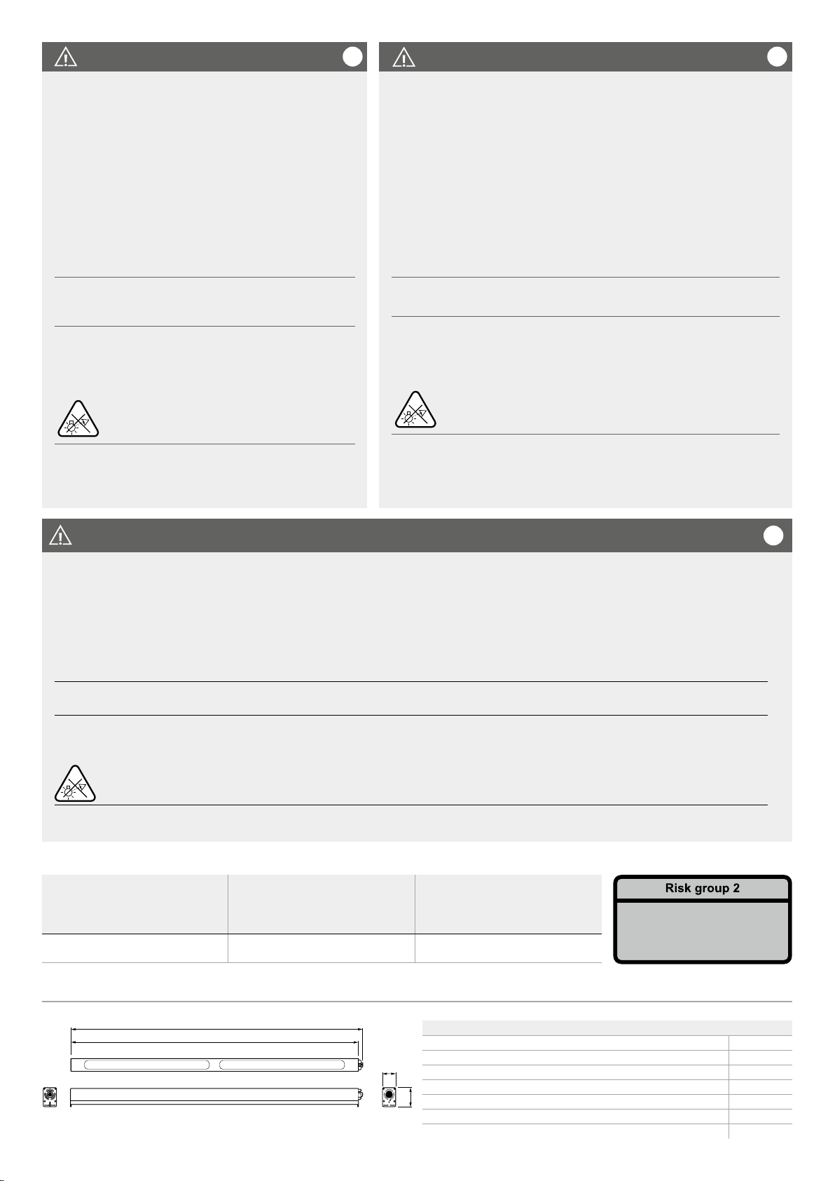
L1
H1
W1
L2
Dimensions / 寸法
Photobiological hazard /
Risques photobiologique /
光生物学的障害
Radiation hazard - Retinal Blue /
Risque du rayonnement - bleu rétinien /
放射線障害 - 網膜青
All other radiation hazards /
Tous les autres risques de
rayonnement /
その他すべての放射線障害
GPL toplighting linear gen2.2 /
リニア
gen2.2
Risk Group 2 / Group de Risque 2 /
リスクグループ 2
Exempt group / Group sans Risque /
免除グループ
GP LED toplighting linear gen2.2
Product dimensions / Dimensions du produit /
製品寸法
mm
L1 1264
L2 1248
W1 55
H1 80
Product weight / Poids du produit /
製品重量
kg
3.23
Caution: Possibly hazardous optical
radiation emitted from this product.
Do not stare at operating lamp.
May be harmful to the eye.
重要重要
!JAP