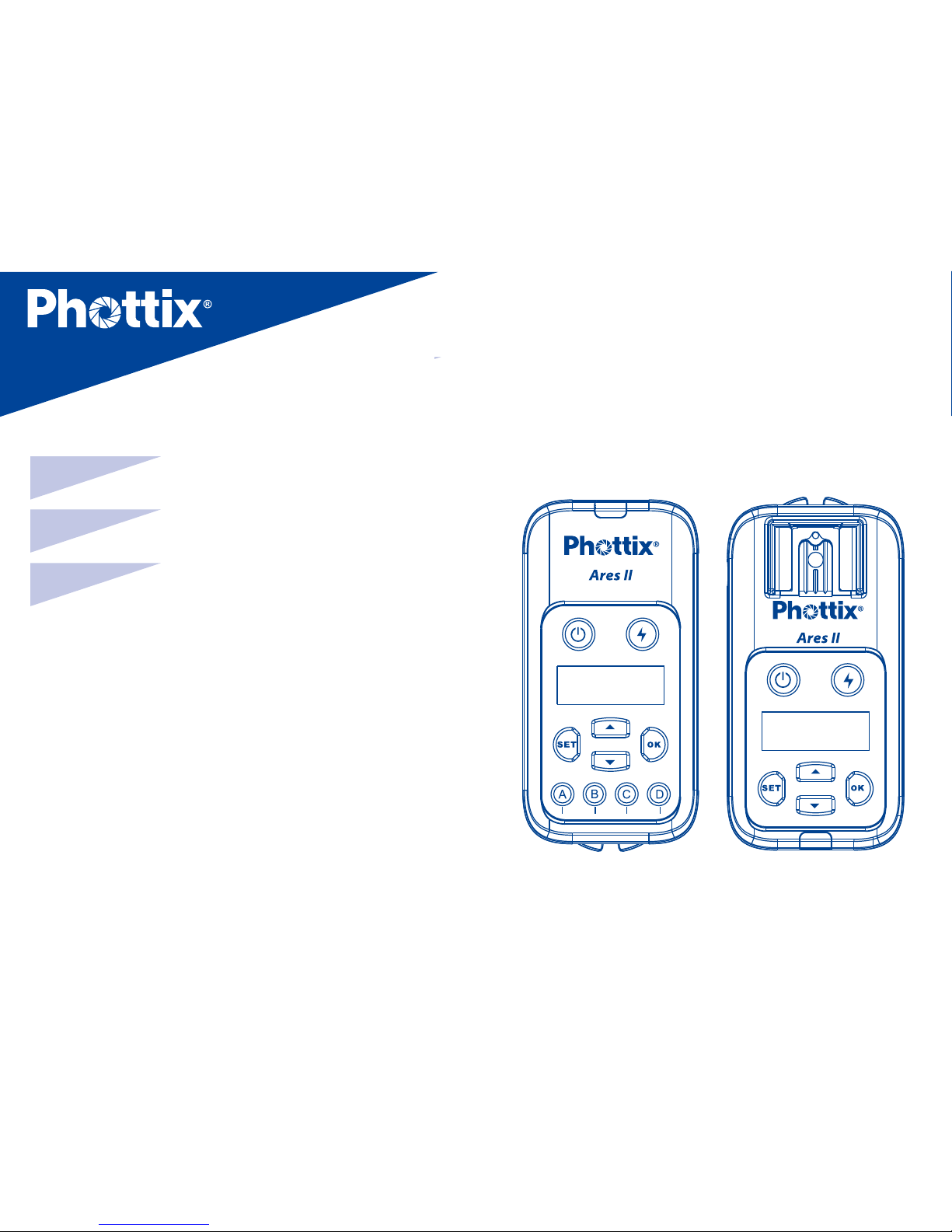
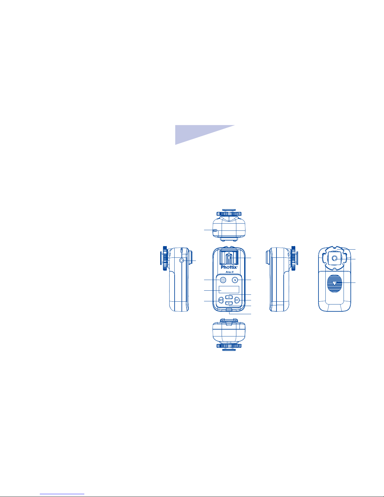
Phottix Ares II User manual

En
1
INSTRUCTION MANUAL
Phottix Ares II Flash Trigger
INSTRUCTION MANUAL 2
说明书 17
說明書 28
En
CnSimp
CnTrad

2
Thank you for purchasing a
Phottix product
Caution: Before using the Ares II Flash Trigger
please read these instruction carefully. Consult
the manual of your camera and ash for setting
specic functions.
The Ares II system consists of transmitter and
receiver and is designed to work in Manual
Exposure mode with the ash and camera and
has no TTL functions.
Compatibility with existing
Phottix Products
Ares II is compatible with Strato II system
when using Channels 1-4 channels,as long
as the transmitter and receiver are set to the
same channel and group:
•The Ares II Transmitter can trigger Strato
II receiver, Mitros+ in Strato II RX mode, and
Indra500/Indra360 studio light in Strato II
RX mode under the above conditions.
•The Ares II Receiver can be triggered
by Strato II transmitter,Odin, Odin II
transmitter(Channels 1-4 only) and Mitros+
in Odin TX mode(Canon or Sony only).

En
3
INSTRUCTION MANUAL
What is in the box:
Transmitter and receiver set:
1. Transmitter unit – 1pc
2. Receiver unit – 1pc
3. Carrying bag – 1pc
4. Phottix 3.5 (male) to 3.5 mm (male) Sync
Cord (40cm)– 1pc
5. 3.5mm (female) to 6.3mm (male)
adapter – 1pc
6. Hand lanyard – 2pcs
7. User manual – 1pc
8. Warranty card – 1pc
Transmitter only
1. Transmitter unit – 1pc
2. User manual – 1pc
3. Hand lanyard – 1pc
4. Warranty card
Receiver only
1. Receiver unit – 1pc
2. User manual – 1pc
3. Phottix 3.5 (male) to 3.5 mm (male) Sync
Cord (40cm)– 1pc
4. 3.5mm (female) to 6.3mm (male)
adapter – 1pc
5. Hand lanyard – 1pc
6. Warranty card

4
Parts
Transmitter
1. Power button
2. LCD display
3. Settings button
4. Group selection buttons (From
left to right is A,B,C,D)
5. Test button
6. Selection button up
7. OK/conrm button
8. Selection button down
9. LED status light
10. Lanyard attachment
11. Battery compartment cover
12. Locking ring
13. Hot shoe contact
14. Hot shoe
15. Locking Pin
1 5
26
37
4
8
9
10
11
12
13
15
14

En
5
INSTRUCTION MANUAL
Receiver
1. Power button
2. LCD display
3. Settings button
4. hot shoe mount
5. Test button
6. Selection button up
7. OK/Conrm button
8. Selection button down
9. LED status light
10. Lanyard attachment
11. Locking ring
12. Coldshoe/ ¼”x20 threaded lug
13. Battery compartment cover
14. 3.5mm sync port
1
2
3
10
14 4 12
13
11
5
6
7
8
9

6
LCD display
1. GR: Group (A、B、C、D)
2. ID :0000~9999 (Supported only when using
channels 5-16)
3. CH: Channels (1~16)
4. :Battery level display
Function and operation
Battery Installation
1. Press and hold the battery cover and push
in the direction indicated on the battery
cover to open. Remove the battery cover.
2. Install AA batteries.
3. Replace the battery cover and push back
into the locked position.
Caution: The Ares II circuitry is designed to
use with Alkaline, NI-CD or Ni-MH battery.
Do not use Lithium AA batteries.
Powering On/O the Ares II
1. Power On:Press and hold the power
button for 2 seconds until the main interface
is displayed on the unit’s LCD.
2. Power O: Press and hold the power
button for 2 second until the main interface
disappears from the unit’s LCD.
3. When the battery power level icon “ ”,

En
7
INSTRUCTION MANUAL
ashes, replace the batteries.
Note:If the Ares II is powered on and
left idle for one hour, it will automatically
power o.
Test button
1. Press the test button on the transmitter
and any ash/ studio light connected to
the Ares II receivers set to the same channel,
group and Digital ID will trigger.
2. Press the test button on the receiver
to re the ash/studio light connected to the
receiver.
LED status light
1. When the transmitter and receiver are
powered on and idle,the LED status light
will ash green.
2. When transmitter is sending commands or
the receiver is receiving commands, the LED
status light will light red.
Connecting the Ares II
Transmitter to the camera
hot shoe
1. Switch o camera and transmitter.
2.
Connect the transmitter to camera hot shoe.

8
3. Rotate the locking ring to tighten.
4. Switch on camera and transmitter.
Connecting hot shoe ashes
to the Ares II Receiver
1. Turn o the ash and the Ares II Receiver.
2. Slide the ash into the receiver’s hot shoe
mount.
3. Lock the ash with the ash’s locking
mechanism.
4. Turn on the ash and the Ares II receiver.
5. Set the ash to Manual mode.
Note: It is not unusual for the ash to
discharge once after turning on the Ares II
Receiver.
Use sync cord to connect Ares
II receiver and hot shoe ash/
studio light
1. Switch o the hot shoe ash/ studio light
and the Ares II receiver.
2. Connect one end of the 3.5mm sync cord
to the 3.5mm port of the Ares II receiver.
3. Connect the other end of the 3.5mm sync
cord to the hot shoe ash or studio light (use
the included 3.5mm to 6.3mm adapter if
required).

En
9
INSTRUCTION MANUAL
4. Switch on the Ares II Receiver and hot shoe
ash/studio light.
5. Set the hot shoe ash/studio light to
manual mode.
Note: It is not unusual for the ash to
discharge once after turning on the Ares II
Receiver.
Transmission channels,
Groups (GR) and Digital ID
The Ares II Flash Trigger System has:
• Channels CH:1~16
• 4 ash groups (GR):A, B, C, D
• Selectable Digital ID:0000 ~9999
(Supported only with channels 5-16).
The Ares II Transmitter
Setting the Groups, Channels
and Digital ID on the
Transmitter
1. Press the Settings button to enter
Channels and Digital ID settings interface.
2. Press the button to cycle the display
between Channels or Digital ID setting. The
selected feature will ash to indicate it is
selected.
3. Press the Selection Buttons Up or
Down to set Channels (CH) and
Digital ID value.

10
4. After setting options,press button to
conrm and exit.
5. Each groups (GR) A,B,C,D has a
corresponding button on the transmitter.
Pressing the corresponding button will
activate or deactivate a group. Active Groups
will be displayed on the LCD, Inactive groups
will not be displayed on the LCD.
Note:
1. Digital ID is only available when using
Channels 5-16.
2. After making adjustments on the
transmitter, if button is not pressed,
settings will be automatically conrmed in
5 seconds.
The Ares II Receiver
Setting Groups (GR), Channels (CH)
and Digital ID on Receiver
1. Press the Settings button to enter
Channels and Digital ID settings interface.
2. Press the button to cycle the display
between Channels, Groups, or Digital ID
setting. The selected feature will ash to
indicate it is selected.
3. Press the Selection Buttons Up or Down
to set Channels (CH), Groups and
Digital ID value.
4. After setting options,press button to
conrm and exit.

En
11
INSTRUCTION MANUAL
Note:
1.Digital ID is only available when using
Channels 5-16.
2. After making adjustments on the
receiver, if button is not pressed,
settings will be automatically conrmed in
5 seconds.
LCD Backlight Brightness
Setting
1. On the Ares II Transmitter or Receiver,
simultaneously press and hold the and
the button until the LCD displays“ ”.
2. Press and to set the brightness of
the backlight(1-8).
After setting the brightness level, press
to exit the adjustment screen.
Note: When transmitter or receiver
is idle for more than 8 seconds, the
backlight will automatically turn off.

12
Technical specications
Frequency 2.4 GHz
Distance 150m+
Channels 16 channels
Groups (GR) 4 groups(A, B, C,D)
Digital ID 0000~9999 (5-16 channels)
Power source 2 AA batteries (Alkaline, Ni-CD, Ni-MH) for transmitter and receivers
Dimension (L92) x (W 46) x (H 41.5) mm(transmitter),
(L 92) x (W 46) x (H 44) mm (receiver)
Weight 65g(transmitter);70g(receiver)—(excluding batteries)
Note:Product design and specication is subject to change without notice.

En
13
INSTRUCTION MANUAL
Warning:
• This product is a precise electronic
instrument. Do not expose to damp
environments or dust.
• Make sure all the devices’ power is switched
o before installing.
• Do not drop or crush.
• This product can not be used in a high
temperature, ammable and explosive
environment.
• If you do not plan to use your Odin TCU and
receiver for a long period of time, it is best
to remove the batteries to prevent possible
battery damage.
Do not use harsh chemical(s) or solvents to
clean the body. Use a soft cloth or lens paper.
• Interference: The Phottix Ares II transmits
and receives radio signals at 2.4 GHz. Its
performance can be aected by electrical
current, magnetic elds, radio signals,
wireless routers, cellular phones, and other
electronic devices. Environmental objects,
such as large buildings or walls, trees, fences,
or cars can also aect performance. If your
Phottix Ares II receiver will not trigger move
its location slightly.

14
EC Declaration of Conformity
We Phottix (HK) Ltd.
Of Unit 1 & 13, 8/F., Block B, Hoi Luen Ind. Centre, 55 Hoi
Yuen Rd., Kwun Tong, Kln., Hong Kong
declare herewith that the product designated below:
Product name:
Phottix Ares II Flash Trigger Transmitter
Model No.: F0702
Product name: Phottix Ares II Flash Trigger Receiver
Model No.: F0701
complies with the relevant fundamental requirements as
per R&TTE Directive 1999/5/EC, insofar as the product is
used correctly, and the following standards or other nor-
mative documents
ETSI EN 300 440-1 V1.6.1 (2010-08)
ETSI EN 300 440-2 V1.4.1 (2010-08)
ETSI EN301 489-1 V1.9.2/2011-09
ETSI EN301 489-17 V2.2.1/2012-09
EN 62479: 2010

En
15
INSTRUCTION MANUAL
FCC Compliance Information
For Transmitter
Company: Phottix (HK) Ltd.
Name:
Phottix Ares II Flash Trigger Transmitter
Model Number:
F0702
FCC ID: P9M-ARES2TX
FCC Interference Statement:
This device complies with part 15 of the FCC Rules.
Operation is subject to the following two conditions:
(1) This device may not cause harmful interference, and
(2) this device must accept any interference received,
including interference that may cause undesired operation.
FCC Radiation Exposure Statement:
This equipment complies with FCC RF radiation exposure
limits set forth for an uncontrolled environment. This
device and its antenna must not be co-located or
operating in conjunction with any other antenna or
transmitter.
Class B Compliance Statement
NOTE: This equipment has been tested and found to
comply with the limits for a Class B digital device, pursuant
to Part 15 of the FCC Rules. These limits are designed to
provide reasonable protection against harmful interference
in a residential installation. This equipment generates, uses
and can radiate radio frequency energy and, if not installed
and used in accordance with the instructions, may cause

16
harmful interference to radio communications. However,
there is no guarantee that interference will not occur in
a particular installation. If this equipment does cause
harmful interference to radio or television reception, which
can be determined by turning the equipment o and on,
the user is encouraged to try to correct the interference by
one or more of the following measures:
- Reorient or relocate the receiving antenna.
- Increase the separation between the equipment and
receiver.
- Connect the equipment into an outlet on a circuit
dierent from that to which the receiver is connected.
- Consult the dealer or an experienced radio/TV technician
for help.
Changes or modications not expressly approved by the
party responsible for compliance could void the user’s
authority to operate the equipment.
For Receiver
This device complies with Part 15 of the FCC Rules.
Operation is subject to the following two conditions: (1)
this device may not cause harmful interference, and (2) this
device must accept any interference received, including
interference that may cause undesired operation.
Changes or modications not expressly approved by the
party responsible for compliance could void the user’s
authority to operate the equipment.

17
感谢您购买 Phottix 产品
注意:在使用 Ares II 无线电触发器前请务必
通读本使用说明书 , 相机和闪光灯的使用方
法,以保证您熟悉操作,正确使用。
Ares II 无线触发器是为手动曝光模式设计的
无线闪光灯引闪系统,由发射器和接收器组
成。本产品采用 2.4GHz 频率,并设有 16 个
无 线 电 频 道 CH,ID(0000 ~ 9999) 和 4
个闪光组 GR,性能稳定,操作简便,适合各
种场合布光使用。
兼容性
Ares II 在 1 ~ 4 频道时兼容 Strato II 系统,
只需发射端和接收器设置为同一频道,对应
组别:
• 发射器可以触发 Strato II 接收器,以及设
为 Strato II RX 模式下的 Indra 系列影楼灯
和 Mitros+ 系列闪光灯;
• 接收器可以被 Strato II 发射器触发,也可
以被 Odin,Odin II 发射器或 Odin TX 模
式下的 Mitros+ (佳能或索尼版)触发。

说明书
CnSimp
18
包装配件
发射接收套装
1. 发射器 -1pc
2. 接收器 -1pc
3. 挂包 -1pc
4. Phottix 带插头软线
3.5+3.5/40cm-1pc
5. 6.3 转接头 -1pc
6. 挂绳 -2pcs
7. 说明书 -1pc
8. 保修卡 -1pc
单发射
1. 发射器 -1pc
2. 说明书 -1pc
3. 挂绳 -1pc
4. 保修卡 -1pc
单接收
1. 接收器 -1pc
2. 说明书 -1pc
3. Phottix 带插头软线
3.5+3.5/40cm-1pc
4. 6.3 转接头 -1pc
5. 挂绳 -1pc
6. 保修卡 -1pc

说明书
CnSimp
19
一 . 部件名称
发射器
1. 电源开关
2. LCD 显示屏
3. 设置按钮
4. 组别按钮 GR( 从左到右依次为 A,B,C,D)
5. 测试按钮
6. 选择按钮(上键)
7. 确认按钮
8. 选择按钮(下键)
9. LED 指示灯
10. 吊环口
11. 电池仓盖
12. 锁环
13. 电子触点
14. 热靴固定座
15. 固定销
1 5
26
37
4
8
9
10
11
12
13
15
14

20
1
2
3
10
14 4 12
13
11
5
6
7
8
9
接收器
1. 电源开关
2. LCD 显示屏
3. 热靴座
4. 设置按钮
5. 测试按钮
6. 选择按钮(上键)
7. 确认按钮
8. 选择按钮 (下键)
9. LED 指示灯
10. 吊环口
11. 锁环
12. 三脚架螺口 / 冷靴插座
13. 电池仓盖
14. 3.5mm 同步端口
Table of contents
Other Phottix Camera Accessories manuals

Phottix
Phottix Nuada S User manual

Phottix
Phottix Odin User manual

Phottix
Phottix Indra360 TTL User manual

Phottix
Phottix Strato II Multi User manual

Phottix
Phottix Laso User manual

Phottix
Phottix Nuada S VLED User manual

Phottix
Phottix odin II TTL User manual

Phottix
Phottix Atlas II User manual

Phottix
Phottix TR-90 User manual

Phottix
Phottix PPL-200 User manual

Phottix
Phottix odin II TTL User manual

Phottix
Phottix Kali600 User manual

Phottix
Phottix Ares User manual

Phottix
Phottix Strato TTL User manual

Phottix
Phottix Trafo Mini User manual

Phottix
Phottix Juno User manual

Phottix
Phottix Trafo User manual

Phottix
Phottix Atlas User manual

Phottix
Phottix Atlas User manual

Phottix
Phottix Laso User manual