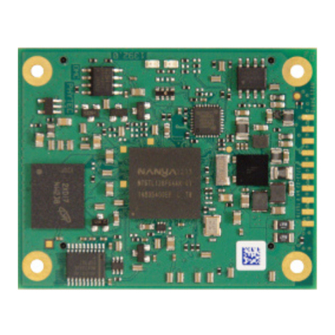
Phytec phyCORE-AM64 Series User manual

A product of a PHYTEC Technology Holding company
phyCORE®-AM64xx
Hardware Manual
Document No.:
L-860e.A0
SOM Prod. No.:
PCM-072
SOM PCB. No.:
1565.1
CB Prod. No.:
PBA-C-25
CB PCB. No.:
1566.1
Edition:
Apr 2022

PCM-072/phyCORE-AM64xx System on Module
L-860e.A0
© PHYTEC America L.L.C. 2022 2
1Table of Contents
1Table of Contents .......................................................................................................................................2
1.1 List of Figures......................................................................................................................................5
1.2 List of Tables.......................................................................................................................................6
2SOM Features ............................................................................................................................................8
3Conventions, Abbreviations and Acronyms.................................................................................................9
3.1 Conventions ........................................................................................................................................9
3.2 Abbreviations and Acronyms ...............................................................................................................9
3.3 Types of Signals................................................................................................................................ 11
4Introduction...............................................................................................................................................12
4.1 Block Diagram ...................................................................................................................................13
4.2 Physical Dimensions .........................................................................................................................14
4.3 Connector Alignment for Mating to Carrier Boards ............................................................................ 16
4.4 Component Placement Diagram........................................................................................................18
4.5 Technical and Electrical Specifications ..............................................................................................20
4.6 Minimum Requirements for Operation ...............................................................................................20
4.7 Solder Jumpers ................................................................................................................................. 21
4.8 Pin Descriptions ................................................................................................................................24
4.9 Pinout Table ......................................................................................................................................25
4.10 Thermal Management .......................................................................................................................32
4.11 Layout Guidelines.............................................................................................................................. 33
4.11.1 High-Speed Differential Signal Routing Guidelines..................................................................... 33
4.11.2 General Signal Routing Guidelines.............................................................................................34
5Power .......................................................................................................................................................34
5.1 Primary System Power (VIN).............................................................................................................35
5.1.1 Primary Power Reference Circuit ............................................................................................... 35
5.2 Backup Power (VBAT).......................................................................................................................37
5.3 Reset.................................................................................................................................................37

PCM-072/phyCORE-AM64xx System on Module
L-860e.A0
© PHYTEC America L.L.C. 2022 3
5.4 Power Sequencing ............................................................................................................................38
5.5 Safe Shutdown and Sudden Power Loss........................................................................................... 39
6System Memory .......................................................................................................................................40
6.1 SOM Memory ....................................................................................................................................40
6.1.1 DDR4 RAM ................................................................................................................................ 40
6.1.2 EEPROM....................................................................................................................................40
6.1.3 eMMC Flash...............................................................................................................................40
6.1.4 OSPI .......................................................................................................................................... 40
6.2 External Memory Bus ........................................................................................................................41
6.2.1 GPMC ........................................................................................................................................41
6.2.2 SD/MMC/SDIO ........................................................................................................................... 43
6.3 System Boot Configuration ................................................................................................................45
7Serial Interfaces .......................................................................................................................................47
7.1 CAN ..................................................................................................................................................47
7.1.1 CAN Pinout ................................................................................................................................47
7.1.2 CAN Reference Circuit ............................................................................................................... 48
7.2 Ethernet.............................................................................................................................................48
7.2.1 Ethernet Pinout...........................................................................................................................49
7.2.2 Ethernet Design In Guide ...........................................................................................................53
7.2.3 Ethernet Reference Circuits........................................................................................................ 58
7.3 FSI ....................................................................................................................................................61
7.3.1 FSI Pinout ..................................................................................................................................62
7.4 I2C .....................................................................................................................................................63
7.4.1 I2C Pinout ...................................................................................................................................63
7.5 PCIe ..................................................................................................................................................63
7.5.1 PCIe Pinout ................................................................................................................................64
7.5.2 PCIe (SERDES) Design In Considerations................................................................................. 64
7.5.3 PCIe Reference Circuits .............................................................................................................64
7.6 SPI ....................................................................................................................................................66

PCM-072/phyCORE-AM64xx System on Module
L-860e.A0
© PHYTEC America L.L.C. 2022 4
7.6.1 SPI Pinout ..................................................................................................................................66
7.7 UART ................................................................................................................................................67
7.7.1 UART Pinout ..............................................................................................................................67
7.8 USB...................................................................................................................................................70
7.8.1 USB Pinout.................................................................................................................................70
7.8.2 USB Design In Considerations ...................................................................................................71
7.8.3 USB Reference Circuits..............................................................................................................72
8Control Interfaces .....................................................................................................................................73
8.1Enhanced Capture ............................................................................................................................ 73
8.1.1 ECAP Pinout .............................................................................................................................. 73
8.2 Enhanced Pulse-Width Modulation.................................................................................................... 74
8.2.1 EPWM Pinout.............................................................................................................................75
8.3 Enhanced Quadrature Encoder Pulse ............................................................................................... 76
8.3.1 EQEP Pinout ..............................................................................................................................76
9Peripheral Interfaces ................................................................................................................................77
9.1 ADC ..................................................................................................................................................77
9.1.1 ADC Pinout ................................................................................................................................77
9.2 CPTS ................................................................................................................................................78
9.2.1 CPTS Pinout .............................................................................................................................. 78
9.3 GPIO .................................................................................................................................................79
9.3.1 GPIO Pinout ...............................................................................................................................80
9.4 TIMER...............................................................................................................................................86
9.4.1 Timer Pinout...............................................................................................................................86
10 Debug Interfaces .....................................................................................................................................87
10.1 JTAG.................................................................................................................................................87
10.1.1 JTAG Pinout...............................................................................................................................88
10.1.2 JTAG Reference Circuit.............................................................................................................. 88
10.2 TRACE (TRC) ...................................................................................................................................88
10.2.1 TRC Pinout................................................................................................................................. 89

PCM-072/phyCORE-AM64xx System on Module
L-860e.A0
© PHYTEC America L.L.C. 2022 5
10.3 UART0 ..............................................................................................................................................90
10.3.1 UART0 Pinout ............................................................................................................................90
10.3.2 UART0 Reference Circuits ......................................................................................................... 90
11 System Interfaces.....................................................................................................................................92
11.1 MAIN Pinout ......................................................................................................................................92
11.2 MCU Pinout.......................................................................................................................................92
12 Integrating and Handling the phyCORE-AM64xx...................................................................................... 93
12.1 Integration ......................................................................................................................................... 93
12.2 Modification ....................................................................................................................................... 93
12.3 In-Field Updates ................................................................................................................................93
12.4 Product Change Management...........................................................................................................94
13 Additional Information...............................................................................................................................95
14 Revision History .......................................................................................................................................97
1.1 List of Figures
Figure 1. phyCORE-AM64xx SOM......................................................................................................................................... 12
Figure 2. phyCORE-AM64xx Block Diagram ......................................................................................................................... 13
Figure 3. phyCORE-AM64xx Dimensions Top View.............................................................................................................. 14
Figure 4. phyCORE-AM64xx Dimensions Bottom View........................................................................................................ 15
Figure 5. phyCORE-AM64xx Dimensions End View.............................................................................................................. 15
Figure 6. Top Down View of Mating Connectors ................................................................................................................. 16
Figure 7. Carrier Board Alignment Hole Placement............................................................................................................. 17
Figure 8. phyCORE-AM64xx Component Placement (processor side)................................................................................. 18
Figure 9. phyCORE-AM64xx Component Placement (connector side)................................................................................. 19
Figure 10. 3-Position Solder Jumper Pad Numbering Scheme ............................................................................................. 21
Figure 11. Jumper Locations (Connector side)...................................................................................................................... 23
Figure 12. Pinout of the phyCORE-Connector...................................................................................................................... 24
Figure 13. Fan design reference circuit................................................................................................................................. 33
Figure 14. Primary Power VIN(VCC_5V0_MAIN) reference circuit....................................................................................... 36
Figure 15. External power input overload protection reference circuit............................................................................... 36
Figure 16. SOM current reader reference circuit.................................................................................................................. 37
Figure 17. Carrier board power reference circuit ................................................................................................................. 38
Figure 18. Example interrupt generation for detecting system power loss ......................................................................... 39
Figure 19. MMC1 Reference Schematic................................................................................................................................ 45
Figure 20. Reference Schematic for BOOTMODE configuration........................................................................................... 47
Figure 21. MCAN0 Reference Schematic .............................................................................................................................. 48

PCM-072/phyCORE-AM64xx System on Module
L-860e.A0
© PHYTEC America L.L.C. 2022 6
Figure 22. RJ45 Reference Schematic ................................................................................................................................... 58
Figure 23. RGMII PHY Reference Schematics........................................................................................................................ 61
Figure 24. PCIe Reference Schematics.................................................................................................................................. 65
Figure 25. Layout example of a ground cutout. The top image shows a filter, and the bottom image shows the ground
plane cutout beneath it. ....................................................................................................................................................... 71
Figure 26. USB-HUB Reference Schematic............................................................................................................................ 72
Figure 27. USB 3.1 Connector Reference Schematic ............................................................................................................ 73
Figure 28. JTAG Reference Schematic................................................................................................................................... 88
Figure 29. UART0 to USB Reference Schematic.................................................................................................................... 90
Figure 30. Simple UART0 Reference Schematic.................................................................................................................... 91
1.2 List of Tables
Table 1 Abbreviations and Acronyms used in this Manual ........................................................................ 10
Table 2 Signal Types Used in this Manual ................................................................................................... 11
Table 3 Technical Specifications..................................................................................................................20
Table 4 Recommended Operating Conditions for the Input and Output Power Domains........................ 20
Table 5 Solder Jumper Settings ...................................................................................................................21
Table 6 Voltage Domain Configurations ...................................................................................................... 22
Table 7 phyCORE-AM64xx Connector X1, Column A Pinout ..................................................................... 25
Table 8 phyCORE-AM64xx Connector X1, Column B Pinout ..................................................................... 27
Table 9 phyCORE-AM64xx Connector X1, Column C Pinout ..................................................................... 28
Table 10 phyCORE-AM64xx Connector X1, Column D Pinout ................................................................... 30
Table 11 Thermal Management Parts...........................................................................................................32
Table 12 External Supply Voltages...............................................................................................................34
Table 13 Reset Pin Description ....................................................................................................................37
Table 14 GPMC Signal Connections at the phyCORE-Connector.............................................................. 41
Table 15 MMC1 Connections at the phyCORE-Connector.......................................................................... 44
Table 16 phyCORE-AM64xx MMC1 Layout Characteristics........................................................................ 44
Table 17 BOOTMODE Description................................................................................................................46
Table 18 MCAN Connections at the phyCORE-Connector ......................................................................... 47
Table 19 Ethernet PHY Default Strapping Configuration............................................................................ 49
Table 20 Ethernet Connections at the phyCORE-Connector...................................................................... 49
Table 21 IEP Connections at the phyCORE-Connector .............................................................................. 52
Table 22 phyCORE-AM64xx CPSW_ETH0 Layout Characteristics ............................................................ 53
Table 23 phyCORE-AM64xx RGMII Timing Requirements.......................................................................... 54
Table 24 phyCORE-AM64xx PRG0_RMGII1 Trace Length Characteristics................................................ 55
Table 25 phyCORE-AM64xx PRG0_RMGII2 Trace Length Characteristics................................................ 55

PCM-072/phyCORE-AM64xx System on Module
L-860e.A0
© PHYTEC America L.L.C. 2022 7
Table 26 phyCORE-AM64xx PRG1_RMGII1 Trace Length Characteristics................................................ 56
Table 27 phyCORE-AM64xx PRG1_RMGII2 Trace Length Characteristics................................................ 56
Table 28 phyCORE-AM64xx RMGII1 Trace Length Characteristics ........................................................... 57
Table 29 phyCORE-AM64xx RMGII2 Trace Length Characteristics ........................................................... 57
Table 30 FSI Connections at the phyCORE-Connector .............................................................................. 62
Table 31 I2C Connections at the phyCORE-Connector ............................................................................... 63
Table 32 PCIe Connections at the phyCORE-Connector ............................................................................ 64
Table 33 phyCORE-AM64xx SERDES0 Layout Characteristics.................................................................. 64
Table 34 SPI Connections at the phyCORE-Connector .............................................................................. 66
Table 35 UART Connections at the phyCORE-Connector .......................................................................... 67
Table 36 SERDES Connections at the phyCORE-Connector ..................................................................... 70
Table 37 USB0 Connections at the phyCORE-Connector........................................................................... 71
Table 38 phyCORE-AM64xx USB0 Layout Characteristics......................................................................... 71
Table 39 phyCORE-AM64xx SERDES0 Layout Characteristics.................................................................. 72
Table 40 ECAP Connections at the phyCORE-Connector .......................................................................... 73
Table 41 EPWM Connections at the phyCORE-Connector ......................................................................... 75
Table 42 EQEP Connections at the phyCORE-Connector .......................................................................... 76
Table 43 ADC Connections at the phyCORE-Connector ............................................................................ 77
Table 44 CPTS Connections at the phyCORE-Connector........................................................................... 78
Table 45 Total Available GPIO ...................................................................................................................... 79
Table 46 GPIO0 Accessibility at phyCORE-Connector ............................................................................... 80
Table 47 GPIO1 Accessibility at phyCORE-Connector ............................................................................... 82
Table 48 MCU_GPIO0 Accessibility at phyCORE-Connector ..................................................................... 83
Table 49 PRG0_PRU0_GPIO Accessibility at phyCORE-Connector .......................................................... 84
Table 50 PRG0_PRU1_GPIO Accessibility at phyCORE-Connector .......................................................... 85
Table 51 PRG1_PRU0_GPIO Accessibility at phyCORE-Connector .......................................................... 85
Table 52 PRG1_PRU1_GPIO Accessibility at phyCORE-Connector .......................................................... 86
Table 53 Timer Signals..................................................................................................................................86
Table 54 JTAG Connections at the phyCORE-Connector........................................................................... 88
Table 55 TRC Connections at the phyCORE-Connector............................................................................. 89
Table 56 UART0 Connections at the phyCORE-Connector ........................................................................ 90
Table 57 MAIN Connections at the phyCORE-Connector........................................................................... 92
Table 58 MCU Connections at the phyCORE-Connector............................................................................ 92
Table 59 Document Revision History........................................................................................................... 97

PCM-072/phyCORE-AM64xx System on Module
L-860e.A0
© PHYTEC America L.L.C. 2022 8
2SOM Features
The phyCORE-AM64xx offers the following features:
•Insert-ready, small (50 mm x 37 mm) System on Module (SOM) subassembly in low EMI design, achieved through
advanced SMD technology
•Populated with the Texas Instruments AM64xx microprocessor (17.2 x 17.2 mm, 0.8 mm pitch BGA)
•Single supply voltage of 5V with on-board power management IC
•Improved interference safety achieved through multi-layer PCB technology and dedicated ground pins
•Up to 2GB DDR4 RAM
•Up to 32GB on-board eMMC
•1x Octal or Quad SPI Flash Subsystem
•1x Gigabit Ethernet PHY
•2x 0.5mm pitch 2x70 pin Samtec connectors that expose the following interfaces:
•1x 32KB I2C EEPROM
•1x SD 3.0 card
•1x Independent 1-lane PCIe Gen2
•1x USB OTG (2.0)
•1x USB3.1-Gen1 Dual Role Device
•5x 10/100/1000 Mbit Ethernet (1x CPSW provided via on-board PHY) (4x PRU_ICSSG)
•2x MCAN with or without CAN-FD support
•9x UART
•6x I2C
•1x JTAG debug port
•1x 12-bit ADC (8x multiplexed analog inputs)
•7x SPI
•3.3V/1.8V GPIOs
•9x EPWM (Enhanced Pulse Width Modulator) modules
•6x Fast Serial Interface Receiver cores
•2x Fast Serial Interface Transmitter cores
•3x ECAP (Enhanced Capture) modules
•3x EQEP (Enhanced Quadrature Encoder Pulse) modules
•1x GPMC (General Purpose Memory Controller) module
•1x TRC (Trace) module
•1x CPTS (Common Platform Time Sync) module
•16x Timer modules
NOTE:
Some of the features listed are not available simultaneously due to the multiplexing options of the various
processor pins. Refer to the sections 5 – 10 of the manual for further information on available multiplexing
options and the pinout of signals.

PCM-072/phyCORE-AM64xx System on Module
L-860e.A0
© PHYTEC America L.L.C. 2022 9
3Conventions, Abbreviations and Acronyms
This hardware manual describes the PCM-072 System on Module, henceforth referred to as phyCORE-AM64xx. The
manual specifies the phyCORE-AM64xx's design and function. Precise specifications for the Texas Instruments AM64xx
microprocessor can be found in the AM64xx Technical Reference Manual.
We refrain from providing detailed part specific information within this manual which can be subject to changes. This is
due to the continuous maintenance of our products. Please read 12.4 Product Change Management for more information.
The BSP delivered with the phyCORE-AM64xx includes drivers and/or software for controlling all components such as
interfaces, memory, etc. Therefore, programming close to the hardware (at the register level) is not necessary in most
cases. For this reason, this manual contains no detailed description of the processor's registers, or information relevant
for software development. Please refer to the AM64xx Technical Reference Manual if such information is needed.
3.1 Conventions
The conventions used in this manual are as follows:
•Signals that are preceded by an "n" or end in z (e.g.: nRD or RDz), are designated as active low signals. That is,
their active state is when they are driven low, or are driving low.
•A "0" indicates a logic zero or low-level signal, while a "1" represents a logic one or high-level signal.
•The hex-numbers given for addresses of I2C devices always represent the 7 most-significant bits (MSB) of the
address byte. The correct value of the least-significant bit (LSB) will depend on the desired command (read (1) or
write (0)) and must be added to get the complete address byte. E.g. given the address in this manual 0x41 => the
complete address byte = 0x83 reads from the device and 0x82 to writes to the device
•Text in blue italics indicate a cross-reference to an internal section of this Document. Click these links to quickly
jump to the applicable part, chapter, table, or figure.
•Text in underlined in blue indicate an external link. Click these links to quickly jump to the applicable URL.
•References made to the phyCORE-Connector always refer to the high density Samtec connectors on the
undersides of the phyCORE-AM64xx System on Module.
3.2 Abbreviations and Acronyms
Many acronyms and abbreviations are used throughout this manual. Use the table below to navigate unfamiliar terms
used in this document.

PCM-072/phyCORE-AM64xx System on Module
L-860e.A0
© PHYTEC America L.L.C. 2022 10
Table 1 Abbreviations and Acronyms used in this Manual
Abbreviation Definition
BSP Board Support Package (Software delivered with the Development Kit including an operating system
(Linux) preinstalled on the module and Development Tools)
CB Carrier Board; used in reference to the phyCORE Development Kit Carrier Board
DDR Double data rate
DRAM Dynamic random access memory
EMC Electromagnetic Compatibility
EMI Electromagnetic Interference
FSI Fast Serial Interface
GPIO General-Purpose Input/Output
GPT General-Purpose Timer
J Solder Jumper: these types of jumpers require solder equipment to remove and place
JP Solderless Jumper: these types of jumpers can be removed and placed by hand with no special tools
JTAG Joint Test Action Group (a serial bus protocol usually used for test purposes)
LCD Liquid Crystal Display
PCB Printed circuit board
PCI Peripheral Component Interconnect
PCIe PCI express
PCM Product Change Management
PCN Product Change Notification
PDI PHYTEC Display Interface; defined to connect PHYTEC display adapter boards, or custom adapters
PEB PHYTEC Expansion Board
PMIC Power management IC
POR Power-on reset
PRU Programmable Realtime Unit
PWM Pulse-width Modulation
RTC Real-time clock
SD Secure Digital
SMT Surface mount technology
SOM System on Module; used in reference to the BOARD DESIGNATOR/ SOM BOARD NAME module
SPI Serial Peripheral Interface
SxUser button Sx(e.g. S1, S2, etc.) used in reference to the available user buttons, or DIP-Switches on
the Carrier Board
UART Universal Asynchronous Receiver/Transmitter
USB Universal Serial Bus

PCM-072/phyCORE-AM64xx System on Module
L-860e.A0
© PHYTEC America L.L.C. 2022 11
3.3 Types of Signals
Different types of signals are brought out at the phyCORE-Connector. Table 2below lists the abbreviations used to specify
the type of a signal.
Table 2 Signal Types Used in this Manual
Signal Type Description Abbreviation
Analog Analog A
Power Supply voltage input PWR_I
Input Digital input I
Output Digital output O
IO Bidirectional input/output I/O
OD-Bidir PU Open drain input/output with pull up OD-BI
OD-Output Open drain output without pull-up, requires an external pull-up OD
5V Input PD 5 V tolerant input with pull down 5V_PD
LVDS Input Differential line pairs 100 ΩLVDS level input LVDS_I
LVDS Output Differential line pairs 100 ΩLVDS level output LVDS_O
USB IO Differential line pairs 90 ΩUSB level bidirectional input/output USB_I/O
ETHERNET Input Differential line pairs 100 ΩEthernet level input ETH_I
ETHERNET Output Differential line pairs 100 ΩEthernet level output ETH_O
ETHERNET IO Differential line pairs 100 ΩEthernet level bidirectional input/output ETH_I/O
PCIe Input Differential line pairs 100 ΩPCIe level input PCIe_I
PCIe Output Differential line pairs 100 ΩPCIe level output PCIe_O
MIPI CSI-2 Input Differential line pairs 100 ΩMIPI CSI-2 level input CSI-2_I

PCM-072/phyCORE-AM64xx System on Module
L-860e.A0
© PHYTEC America L.L.C. 2022 12
4Introduction
Figure 1. phyCORE-AM64xx SOM
The phyCORE-AM64xx belongs to PHYTEC’s phyCORE System on Module family. The phyCORE boards integrate all core
elements of a microprocessor system on a single module and are designed in a manner that ensures their easy expansion
and embedding in peripheral hardware developments.
The phyCORE-AM64xx is a small (50mm x 37mm) insert-ready System on Module populated with the Texas Instrument’s
AM64xx microprocessor. Its universal design enables its insertion in a wide range of embedded applications. Most of the
microprocessor signals and ports extend from the microprocessor to the high-density pitch (0.5 mm) connectors aligning
two sides of the board, allowing it to be plugged directly into a target application.
Implementing a phyCORE-AM64xx SOM as the "core" of your embedded design allows for increased focus on hardware
peripherals and firmware without expending resources to "re-invent" microprocessor circuitry or other commonly used
circuitry that has already been implemented on the phyCORE-AM64xx including a DDR, an eMMC, a power distribution
network, an Ethernet PHY, an RTC, and an EEPROM. Production-ready board support packages (BSPs), design services for
our hardware, and lifecycle maintenance of our parts will further reduce development time, risk, and allows for increased
focus on product expertise. Take advantage of PHYTEC products to shorten time-to-market, reduce development costs,
and avoid substantial design issues and risks. With this new innovative full system solution, new ideas can be brought to
market in the most timely and cost-efficient manner.
Precise specifications for the processor populating the board can be found in the applicable processor reference manual
or datasheet. The descriptions in this manual are based on the Texas Instrument’s AM64xx. No descriptions of compatible
microprocessor derivative functions are included; these are not relevant for the basic functioning of the phyCORE-AM64xx.

PCM-072/phyCORE-AM64xx System on Module
L-860e.A0
© PHYTEC America L.L.C. 2022 13
4.1 Block Diagram
Figure 2. phyCORE-AM64xx Block Diagram

PCM-072/phyCORE-AM64xx System on Module
L-860e.A0
© PHYTEC America L.L.C. 2022 14
4.2 Physical Dimensions
Figure 3. phyCORE-AM64xx Dimensions Top View

PCM-072/phyCORE-AM64xx System on Module
L-860e.A0
© PHYTEC America L.L.C. 2022 15
Figure 4. phyCORE-AM64xx Dimensions Bottom View
Figure 5. phyCORE-AM64xx Dimensions End View

PCM-072/phyCORE-AM64xx System on Module
L-860e.A0
© PHYTEC America L.L.C. 2022 16
4.3 Connector Alignment for Mating to Carrier Boards
The phyCORE-AM64xx has two mounting holes in the lower left and upper right corner sized for M2.5 screws/components.
It is recommended to use the following mounting hardware to secure the SOM to a mating carrier board:
•2x M2.5x5mm Female-Female Standoffs
•4x M2.5x4mm Screws
•4x M2.5 Washers
Figure 6. Top Down View of Mating Connectors

PCM-072/phyCORE-AM64xx System on Module
L-860e.A0
© PHYTEC America L.L.C. 2022 17
Figure 7. Carrier Board Alignment Hole Placement

PCM-072/phyCORE-AM64xx System on Module
L-860e.A0
© PHYTEC America L.L.C. 2022 18
4.4 Component Placement Diagram
Figure 8. phyCORE-AM64xx Component Placement (processor side)
A searchable pdf of the phyCORE-AM64xx component placement (processor side) can be found here: TBD.

PCM-072/phyCORE-AM64xx System on Module
L-860e.A0
© PHYTEC America L.L.C. 2022 19
Figure 9. phyCORE-AM64xx Component Placement (connector side)
A searchable pdf of the phyCORE-AM64xx component placement (connector side) can be found here: TBD.

PCM-072/phyCORE-AM64xx System on Module
L-860e.A0
© PHYTEC America L.L.C. 2022 20
4.5 Technical and Electrical Specifications
Table 3 Technical Specifications
Specification
Dimensions 50 mm x 37 mm x 4.8 mm
Mass ~16.65g
Storage Temperature -40C to +85C
Operating Temperature -40C to +85C
Typical Idling Power Consumption12.75W1
1Calculated from idle Ivcc in Table 4
Table 4 Recommended Operating Conditions for the Input and Output Power Domains
Symbol Description Conditions Min Typical Max Unit
VIN 5V SOM input voltage
4.5 5 5.5 VDC
VBAT Backup battery for RTC
1.2 3 5.5 VDC
IVIN 5V SOM operating current
Idle in Linux with external interfaces
down/disconnected (except for Serial RS-232 and SD
card)
- 367 2- mA
Measured while device was under load1- 525 3- mA
Measured with VDD_3V3_OUT supplying 2A of current
alongside the test suite in the row above - 1845 - mA
IVBAT RTC operating current
- 40 - nA
1The load included the following interfaces/commands: the “memtester 500M” command was run, ETH0 was plugged in with iperf3 running, and two instances of the
following command were run (yes > /dev/null &), The Yes Command
2This measurement does not include the current draw from VDD_3V3_OUT of 277mA.
3This measurement does not include the current draw from VDD_3V3_OUT of 290mA.
4.6 Minimum Requirements for Operation
PHYTEC recommends the following minimum requirements for basic operation of the phyCORE-AM64xx SOM:
•Mount the SOM into the mating carrier board using two BTH-070-01-L-D-A-K-TR 0.5mm 2x70 Samtec connectors.
•Connect all available 5V input pins to a power supply on a custom carrier board that provides at least 2000 mA
(1000 mA if VDD_3V3_OUT is not used in your design).
•Connect all ground pins to ground.
•Implement a power sequencing circuit to avoid driving external power to the I/O pins of the PHYCORE-AM64xx
SOM before the module is fully powered up. More details on this can be found in section 5.4 Power Sequencing.
•Implement at least one of the supported boot devices to support loading and executing application software.
Refer to section 6.3 System Boot Configuration for more details regarding supported boot modes. The phyCORE-
AM64xx SOM provides an on-board eMMC, but it is recommended to support another boot source for
development and debugging. PHYTEC suggests SD boot for which an example circuit can be seen in section 6.2.2.3
MMC1 Reference Circuit
Table of contents
Other Phytec Single Board Computer manuals

Phytec
Phytec phyCORE-AM65x User manual

Phytec
Phytec phyBoard Wega AM335x User guide

Phytec
Phytec PhyBOARD-Mira i.MX6 User manual

Phytec
Phytec phyCORE-OMAP44 Series User manual

Phytec
Phytec phyCORE-TC1796 User manual

Phytec
Phytec phyCORE-AM64xx User manual

Phytec
Phytec phyCORE-AM335x User manual

Phytec
Phytec phyCORE-i.MX7 User manual

Phytec
Phytec phyCORE-ADuC812 Programming manual

Phytec
Phytec phyCORE-P8xC51Mx2 User manual