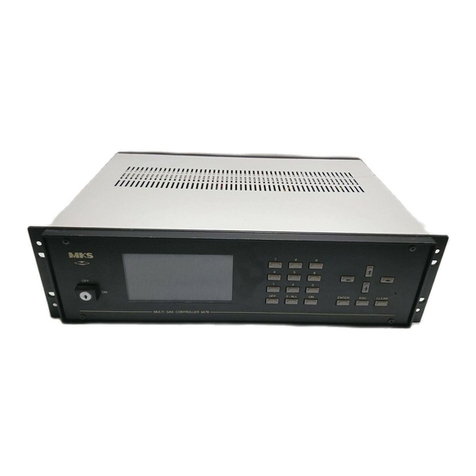
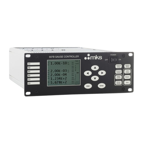
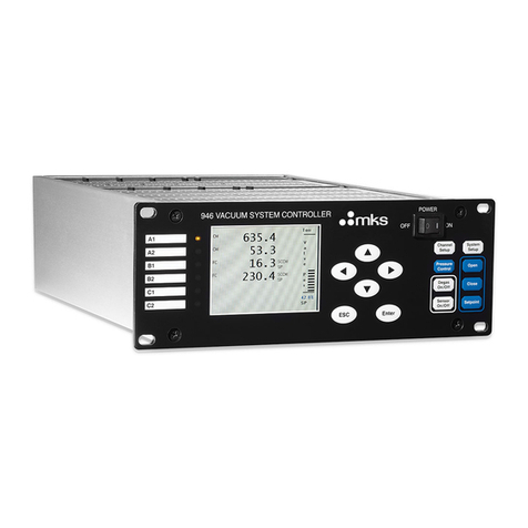
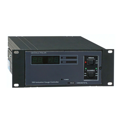
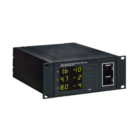
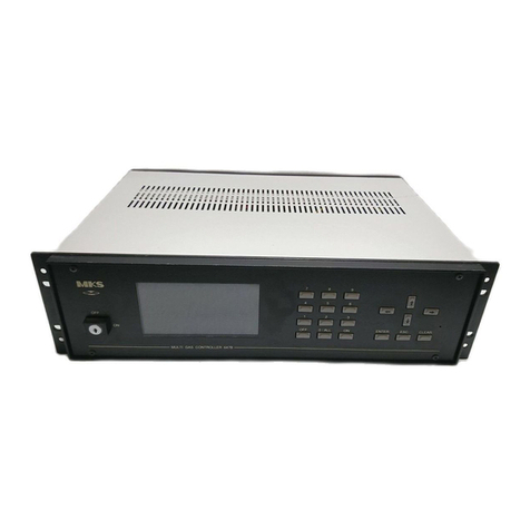
MKS 350 Series User manual

Series 350
Instruction Manual
UHV Gauge Controller
Instruction manual part number 350010
Revision G - March 2020


Instruction Manual
Series 350
This Instruction Manual is for use with Series 350 Ultra High
Vacuum Gauge Controllers. A list of applicable catalog
numbers is provided on the following page.
© 2020 MKS Instruments, Inc. All rights reserved.
Granville-Phillips®, Stabil-Ion®, and Convectron®are registered trademarks, and mksinstTM
is a trademark of MKS Instruments Inc. All other trademarks and registered trademarks are
the properties of their respective owners.
UHV Gauge Controller
Customer Service / Technical Support:
MKS Global Headquarters
2 Tech Drive, Suite 201
Andover MA, 01810 USA
Phone: +1-833-986-1686
Email: insidesales@mksinst.com
Visit our website at www.mksinst.com

Series 350 UHV Gauge Controller
Catalog numbers for Series 350 Ultra High Vacuum Gauge Controllers
Controller configured for a Series 274 UHV nude Bayard-Alpert gauge, with 1-line display, electron
bombardment degas, and remote input/output interface
Half-rack mount 350501 - # - # #
Left mount for 19-inch rack 350502 - # - # #
Center mount for 19-inch rack 350503 - # - # #
Options:
None 0
RS-232 A
RS-232 or RS-485 switchable with 4 setpoints F
2 setpoint relays for the ionization gauge G
Measurement Units:
Torr T
mbar M
pascal P
Power cord options:
North American 115 V 1
North American 240 V 2
Universal Europe 220 V 3
United Kingdom 240 V 4
Controller configured for a Series 274 UHV nude Bayard-Alpert gauge and dual Convectron gauge operation,
with 3-line display, electron bombardment degas, and remote input/output interface
Half-rack mount 350507 - # - # #
Left mount for 19-inch rack 350508 - # - # #
Center mount for 19-inch rack 350509 - # - # #
Options:
None 0
RS-232 or RS-485 switchable with 4 setpoints F
Measurement Units:
Torr T
mbar M
pascal P
Power cord options:
North American 115 V 1
North American 240 V 2
Universal Europe 220 V 3
United Kingdom 240 V 4

350 UHV Gauge Controller Instruction Manual - 350010 5
Contents
Chapter 1 Before You Begin . . . . . . . . . . . . . . . . . . . . . . . . . . . . . . . . . . 9
1.1 About These Instructions . . . . . . . . . . . . . . . . . . . . . . . . . . . 9
1.2 Caution and Warning Statements . . . . . . . . . . . . . . . . . . . . 9
1.3 Read and Follow These Instructions . . . . . . . . . . . . . . . . . . 10
1.4 System Grounding . . . . . . . . . . . . . . . . . . . . . . . . . . . . . . . 10
1.5 Explosive Gases . . . . . . . . . . . . . . . . . . . . . . . . . . . . . . . . . 11
1.6 Implosion / Explosion . . . . . . . . . . . . . . . . . . . . . . . . . . . . . 11
1.7 Operation . . . . . . . . . . . . . . . . . . . . . . . . . . . . . . . . . . . . . . 11
1.8 Customer Service . . . . . . . . . . . . . . . . . . . . . . . . . . . . . . . . 12
Chapter 2 350 Gauge Controller . . . . . . . . . . . . . . . . . . . . . . . . . . . . . . 13
2.1 General Description . . . . . . . . . . . . . . . . . . . . . . . . . . . . . . 13
Available Options . . . . . . . . . . . . . . . . . . . . . . . . . . . . . . . . 13
IG Cables . . . . . . . . . . . . . . . . . . . . . . . . . . . . . . . . . . . . . . 14
Mounting Options . . . . . . . . . . . . . . . . . . . . . . . . . . . . . . . . 14
2.2 Installation . . . . . . . . . . . . . . . . . . . . . . . . . . . . . . . . . . . . . 14
Line Voltage Selection . . . . . . . . . . . . . . . . . . . . . . . . . . . . 14
Mounting Configurations . . . . . . . . . . . . . . . . . . . . . . . . . . 17
EMC Compliance . . . . . . . . . . . . . . . . . . . . . . . . . . . . . . . . 19
Ionization Gauge Types and Installation . . . . . . . . . . . . . . . 19
Cable Installation . . . . . . . . . . . . . . . . . . . . . . . . . . . . . . . . 20
2.3 Wiring . . . . . . . . . . . . . . . . . . . . . . . . . . . . . . . . . . . . . . . . 23
System Ground Test Procedure . . . . . . . . . . . . . . . . . . . . . . 24
2.4 Controls and Indicators . . . . . . . . . . . . . . . . . . . . . . . . . . . . 26
Units of Measure [1] . . . . . . . . . . . . . . . . . . . . . . . . . . . . . . 26
Power On/Off [4] . . . . . . . . . . . . . . . . . . . . . . . . . . . . . . . . 27
Ion Gauge On/Off [2] . . . . . . . . . . . . . . . . . . . . . . . . . . . . 27
Degas On/Off [3] . . . . . . . . . . . . . . . . . . . . . . . . . . . . . . . . 27
Remote Input/Output [5] . . . . . . . . . . . . . . . . . . . . . . . . . . . 27
2.5 Ionization Gauge Theory of Operation . . . . . . . . . . . . . . . . 28
350 UHV Gauge Controller Specifications . . . . . . . . . . . . . 29
Chapter 3 Electrometer Module . . . . . . . . . . . . . . . . . . . . . . . . . . . . . . . 33
3.1 Introduction . . . . . . . . . . . . . . . . . . . . . . . . . . . . . . . . . . . . 33
3.2 Units of Measure . . . . . . . . . . . . . . . . . . . . . . . . . . . . . . . . . 33
3.3 Display Update Rate Switch [8] . . . . . . . . . . . . . . . . . . . . . 34
3.4 Degas Timer Override [6] . . . . . . . . . . . . . . . . . . . . . . . . . . 34
3.5 Calibration Switch [9] . . . . . . . . . . . . . . . . . . . . . . . . . . . . . 34
3.6 Emission Range Switch [10] . . . . . . . . . . . . . . . . . . . . . . . . 35
3.7 Emission Adjustment [11] . . . . . . . . . . . . . . . . . . . . . . . . . . 35
3.8 Sensitivity Adjustment [12] . . . . . . . . . . . . . . . . . . . . . . . . . 36
3.9 Relative Gas Sensitivities . . . . . . . . . . . . . . . . . . . . . . . . . . . 36
3.10 Analog Output . . . . . . . . . . . . . . . . . . . . . . . . . . . . . . . . . . 37
3.11 Electrometer Calibration . . . . . . . . . . . . . . . . . . . . . . . . . . . 39

350 UHV Gauge Controller Instruction Manual - 350010 6
Electrometer Span Adjustment [13] . . . . . . . . . . . . . . . . . . . 39
Overpressure Shutdown Adjustment [14] . . . . . . . . . . . . . . 39
A/D calibration [15] . . . . . . . . . . . . . . . . . . . . . . . . . . . . . . 39
Chapter 4 Process Control Module . . . . . . . . . . . . . . . . . . . . . . . . . . . . 41
4.1 Introduction . . . . . . . . . . . . . . . . . . . . . . . . . . . . . . . . . . . . 41
4.2 Process Control System Connections . . . . . . . . . . . . . . . . . . 41
4.3 To Display a Setpoint . . . . . . . . . . . . . . . . . . . . . . . . . . . . . 41
4.4 To Modify a Setpoint . . . . . . . . . . . . . . . . . . . . . . . . . . . . . . 42
4.5 Relay Polarity Setting . . . . . . . . . . . . . . . . . . . . . . . . . . . . . 42
4.6 Relay Disable . . . . . . . . . . . . . . . . . . . . . . . . . . . . . . . . . . . 43
4.7 Pin Assignments . . . . . . . . . . . . . . . . . . . . . . . . . . . . . . . . . 44
4.8 Process Control Operation . . . . . . . . . . . . . . . . . . . . . . . . . 44
Setpoint Display and Adjustment . . . . . . . . . . . . . . . . . . . . 44
Manual Override [16] . . . . . . . . . . . . . . . . . . . . . . . . . . . . . 45
4.9 Process Control Theory of Operation . . . . . . . . . . . . . . . . . 45
Process Control Specifications . . . . . . . . . . . . . . . . . . . . . . 45
Chapter 5 RS-232 Module . . . . . . . . . . . . . . . . . . . . . . . . . . . . . . . . . . 47
5.1 Introduction . . . . . . . . . . . . . . . . . . . . . . . . . . . . . . . . . . . . 47
5.2 RS-232 Interface . . . . . . . . . . . . . . . . . . . . . . . . . . . . . . . . . 47
Selecting the Byte Format . . . . . . . . . . . . . . . . . . . . . . . . . . 47
Baud Rate . . . . . . . . . . . . . . . . . . . . . . . . . . . . . . . . . . . . . . 47
Character Framing . . . . . . . . . . . . . . . . . . . . . . . . . . . . . . . 47
Talk-Only Mode . . . . . . . . . . . . . . . . . . . . . . . . . . . . . . . . . 48
Handshake Line Control Switches . . . . . . . . . . . . . . . . . . . . 48
Invert RTS Switch . . . . . . . . . . . . . . . . . . . . . . . . . . . . . . . . 48
5.3 Operation . . . . . . . . . . . . . . . . . . . . . . . . . . . . . . . . . . . . . . 49
Command Syntax . . . . . . . . . . . . . . . . . . . . . . . . . . . . . . . . 49
DG . . . . . . . . . . . . . . . . . . . . . . . . . . . . . . . . . . . . . . . 49
DGS . . . . . . . . . . . . . . . . . . . . . . . . . . . . . . . . . . . . . . . 50
DS IG . . . . . . . . . . . . . . . . . . . . . . . . . . . . . . . . . . . . . . . 50
IG1 . . . . . . . . . . . . . . . . . . . . . . . . . . . . . . . . . . . . . . . 50
IG2 . . . . . . . . . . . . . . . . . . . . . . . . . . . . . . . . . . . . . . . 50
Error Messages . . . . . . . . . . . . . . . . . . . . . . . . . . . . . . . . . . 51
5.4 RS-232 Theory of Operation . . . . . . . . . . . . . . . . . . . . . . . . 51
Handshaking . . . . . . . . . . . . . . . . . . . . . . . . . . . . . . . . . . . . 51
CTS, DSR . . . . . . . . . . . . . . . . . . . . . . . . . . . . . . . . . . . . . . 52
DCD . . . . . . . . . . . . . . . . . . . . . . . . . . . . . . . . . . . . . . . . . . 52
DTR . . . . . . . . . . . . . . . . . . . . . . . . . . . . . . . . . . . . . . . . . . 52
RTS . . . . . . . . . . . . . . . . . . . . . . . . . . . . . . . . . . . . . . . . . . . 52
5.5 Reversing the Polarity of RTS . . . . . . . . . . . . . . . . . . . . . . . 52
5.6 RS-232 Troubleshooting . . . . . . . . . . . . . . . . . . . . . . . . . . . 52
RS-232 Specifications . . . . . . . . . . . . . . . . . . . . . . . . . . . . . 53

350 UHV Gauge Controller Instruction Manual - 350010 7
Chapter 6 Digital Interface Module . . . . . . . . . . . . . . . . . . . . . . . . . . . . 55
6.1 Process Control Installation . . . . . . . . . . . . . . . . . . . . . . . . . 55
6.2 Process Control System Connections . . . . . . . . . . . . . . . . . . 55
6.3 To Display a Setpoint . . . . . . . . . . . . . . . . . . . . . . . . . . . . . 56
6.4 To Modify a Setpoint . . . . . . . . . . . . . . . . . . . . . . . . . . . . . . 56
6.5 Process Control Connector . . . . . . . . . . . . . . . . . . . . . . . . . 57
6.6 Process Control Display Assignment . . . . . . . . . . . . . . . . . . 57
6.7 Manual Override . . . . . . . . . . . . . . . . . . . . . . . . . . . . . . . . 58
6.8 RS-232/RS-485 Installation . . . . . . . . . . . . . . . . . . . . . . . . . 58
6.9 Setpoint Display and Adjustment . . . . . . . . . . . . . . . . . . . . 60
6.10 Switch Settings . . . . . . . . . . . . . . . . . . . . . . . . . . . . . . . . . . 61
6.11 RS-232 Connectors . . . . . . . . . . . . . . . . . . . . . . . . . . . . . . . 64
6.12 RS-485 Connector . . . . . . . . . . . . . . . . . . . . . . . . . . . . . . . . 65
6.13 Operation . . . . . . . . . . . . . . . . . . . . . . . . . . . . . . . . . . . . . . 65
RS-232/RS-485 Command Syntax . . . . . . . . . . . . . . . . . . . . 66
DG . . . . . . . . . . . . . . . . . . . . . . . . . . . . . . . . . . . . . . . 66
DGS . . . . . . . . . . . . . . . . . . . . . . . . . . . . . . . . . . . . . . . 66
IGB . . . . . . . . . . . . . . . . . . . . . . . . . . . . . . . . . . . . . . . 67
RD . . . . . . . . . . . . . . . . . . . . . . . . . . . . . . . . . . . . . . . 67
F1 . . . . . . . . . . . . . . . . . . . . . . . . . . . . . . . . . . . . . . . 67
F2 . . . . . . . . . . . . . . . . . . . . . . . . . . . . . . . . . . . . . . . 67
PC . . . . . . . . . . . . . . . . . . . . . . . . . . . . . . . . . . . . . . . 67
Error Messages . . . . . . . . . . . . . . . . . . . . . . . . . . . . . . . . . . 69
RS-232/RS-485 Signals . . . . . . . . . . . . . . . . . . . . . . . . . . . . 69
RS-232 and RS-485 Start Characters . . . . . . . . . . . . . . . . . . 70
6.14 Troubleshooting . . . . . . . . . . . . . . . . . . . . . . . . . . . . . . . . . 71
Host Computer Interface Specifications . . . . . . . . . . . . . . . . 71
Chapter 7 Convectron Gauge Module . . . . . . . . . . . . . . . . . . . . . . . . . . 73
7.1 Introduction . . . . . . . . . . . . . . . . . . . . . . . . . . . . . . . . . . . . 73
7.2 Safety Instructions . . . . . . . . . . . . . . . . . . . . . . . . . . . . . . . . 75
7.3 Installation Considerations . . . . . . . . . . . . . . . . . . . . . . . . . 77
7.4 Orientation . . . . . . . . . . . . . . . . . . . . . . . . . . . . . . . . . . . . . 77
7.5 Mounting . . . . . . . . . . . . . . . . . . . . . . . . . . . . . . . . . . . . . . 78
Compression Mount . . . . . . . . . . . . . . . . . . . . . . . . . . . . . . 79
1/8 NPT Mount . . . . . . . . . . . . . . . . . . . . . . . . . . . . . . . . . . 79
NW Flange . . . . . . . . . . . . . . . . . . . . . . . . . . . . . . . . . . . . . 79
7.6 Reading Pressure . . . . . . . . . . . . . . . . . . . . . . . . . . . . . . . . . 80
Operation Below 10–3 Torr . . . . . . . . . . . . . . . . . . . . . . . . . 80
Use with Gases Other Than N2 or Air . . . . . . . . . . . . . . . . . 80
Indicated Versus True Pressure . . . . . . . . . . . . . . . . . . . . . . 81
7.7 Unit of Measure [16 and 17] . . . . . . . . . . . . . . . . . . . . . . . . 86
7.8 Display Update Rate Switch [18] . . . . . . . . . . . . . . . . . . . . 86
7.9 Analog Output [20 and 21] . . . . . . . . . . . . . . . . . . . . . . . . . 87
7.10 Calibration . . . . . . . . . . . . . . . . . . . . . . . . . . . . . . . . . . . . . 88

350 UHV Gauge Controller Instruction Manual - 350010 8
Analog Output Full Scale Adjustment [27] . . . . . . . . . . . . . 88
7.11 Analog Output Offset for Gauges A and B [28 and 29] . . . . 89
Zero Adjustment [23 and 26] . . . . . . . . . . . . . . . . . . . . . . . 90
Atmosphere Adjustment [22 and 25] . . . . . . . . . . . . . . . . . . 90

350 UHV Gauge Controller Instruction Manual - 350010 9
350 Controller Electrometer PC Module RS-232 Module PC/RS-232/RS-485
Module
Chapter 1 Before You Begin
1.1 About These Instructions These instructions explain how to install, operate, and maintain the
Series 350 UHV gauge controller.
This chapter explains caution and warning statements, which must be
adhered to at all times; explains your responsibility for reading and
following all instructions; defines the terms that are used throughout this
instruction manual; and explains how to contact customer service.
1.2 Caution and Warning
Statements
This manual contains caution and warning statements with which you must
comply to prevent inaccurate measurement, property damage, or personal
injury.
Caution and warning statements comply with American Institute of
Standards Z535.1-2002 through Z535.5-2002, which set forth voluntary
practices regarding the content and appearance of safety signs, symbols,
and labels.
Each caution or warning statement explains:
a. The specific hazard that you must prevent or unsafe practice that you
must avoid,
b. The potential result of your failure to prevent the specified hazard or
avoid the unsafe practice, and
c. What you must do to prevent the specified hazardous result.
CAUTION
Caution statements alert you to hazards or unsafe
practices that could result in inaccurate
measurement, minor personal injury or property
damage.
Each caution statement explains what you must do to prevent or
avoid the potential result of the specified hazard or unsafe
practice.
WARNING
Warning statements alert you to hazards or unsafe
practices that could result in severe property damage or
personal injury due to electrical shock, fire, or explosion.
Each warning statement explains what you must do to prevent
or avoid the potential result of the specified hazard or unsafe
practice.

Chapter 1
10 350 UHV Gauge Controller Instruction Manual - 350010
1.3 Read and Follow These
Instructions
You must comply with all instructions while you are installing, operating,
or maintaining the Series 350 UHV controller or vacuum gauges. Failure to
comply with the instructions violates standards of design, manufacture, and
intended use of the controller. MKS Instruments, Inc. disclaims all liability
for the customer's failure to comply with the instructions.
•Read instructions – Read all instructions before installing or operating the
product.
•Follow instructions – Follow all installation, operating and maintenance
instructions.
•Retain instructions – Retain the instructions for future reference.
•Heed warnings and cautions – Adhere to all warnings and caution
statements on the product and in these instructions.
•Parts and accessories – Install only those replacement parts and
accessories that are recommended by MKS. Substitution of parts is
hazardous.
Danger - High Voltage 180 Vdc is present on the Series 350 Controller on the cable and the
ionization gauge when the gauge is turned ON. Voltages as high as 700 Vdc
peak are present during degas.
1.4 System Grounding Grounding, though simple, is very important! Be certain that ground circuits
are correctly used on your ion gauge power supplies, gauges, and vacuum
chambers, regardless of their manufacturer. Safe operation of vacuum
equipment, including the Series 350 High Vacuum Gauge Controller,
requires grounding of all exposed conductors of the gauges, the controller
and the vacuum system. LETHAL VOLTAGES may be established under
some operating conditions unless correct grounding is provided.
Ion producing equipment, such as ionization gauges, mass spectrometers,
sputtering systems, etc., from many manufacturers may, under some
conditions, provide sufficient electrical conduction via a plasma to couple
a high voltage electrode potential to the vacuum chamber. If exposed
conductive parts of the gauge, controller, and chamber are not properly
grounded, they may attain a potential near that of the high voltage electrode
during this coupling. Potential fatal electrical shock could then occur
because of the high voltage between these exposed conductors and ground.
WARNING
Read these safety notices and warnings before installing,
using, or servicing this equipment. If you have any
doubts regarding the safe use of this equipment, contact
the MKS Customer Service department.

Before You Begin
350 UHV Gauge Controller Instruction Manual - 350010 11
350 Controller Electrometer PC Module RS-232 Module PC/RS-232/RS-485
Module
1.5 Explosive Gases Do not use Series 350 instruments to measure the pressure of explosive or
combustible gases or gas mixtures. Ionization gauge filaments operate at
high temperatures.
1.6 Implosion / Explosion Glass ionization gauges, if roughly handled, may implode under vacuum
causing flying glass which may injure personnel. If pressurized above
atmospheric pressure, glass tubes may explode. A substantial shield should
be placed around vacuum glassware to prevent injury to personnel.
Danger of injury to personnel and damage to equipment exists on all
vacuum systems that incorporate gas sources or involve processes capable
of pressuring the system above the limits it can safely withstand.
For example, danger of explosion in a vacuum system exists during
backfilling from pressurized gas cylinders because many vacuum devices
such as ionization gauge tubes, glass windows, glass belljars, etc., are not
designed to be pressurized.
Do not attach cables to glass gauge pins while the gauge is under vacuum.
Accidental bending of the pins may cause the glass to break and implode.
Cables, once installed, should be secured to the system to provide strain
relief for the gauge tube pins.
Install suitable devices that will limit the pressure from external gas sources
to the level that the vacuum system can safely withstand. In addition, install
suitable pressure relief valves or rupture disks that will release pressure at a
level considerably below that pressure which the system can safely
withstand.
Confirm that these safety devices are properly installed before installing the
Series 350 Vacuum Gauge Controller (VGC). In addition, check that (1) the
proper gas cylinders are installed, (2) gas cylinder valve positions are
correct on manual systems, and (3) the automation is correct on automated
systems.
1.7 Operation It is the installer's responsibility to ensure that the automatic signals
provided by the process control module are always used in a safe manner.
Carefully check manual operation of the system and the setpoint
programming before switching to automatic operation. Where an
equipment malfunction could cause a hazardous situation, always provide
for fail-safe operation. As an example, in an automatic backfill operation
where a malfunction might cause high internal pressures, provide an
appropriate pressure relief device.

Chapter 1
12 350 UHV Gauge Controller Instruction Manual - 350010
1.8 Customer Service Some minor problems are readily corrected on site. If the product requires
service, contact the MKS Technical Support Department at
+1-833-986-1686. If the product must be returned to the factory for service,
request a Return Material Authorization (RMA) from MKS. Do not return
products without first obtaining an RMA. In some cases a hazardous
materials disclosure form may be required. The MKS Customer Service
Representative will advise you if the hazardous materials document is
required.
When returning products to MKS, be sure to package the products to
prevent shipping damage. Shipping damage on returned products as a result
of inadequate packaging is the Buyer's responsibility.
For Customer Service / Technical Support:
MKS Global Headquarters
2 Tech Drive, Suite 201
Andover MA, 01810 USA
Phone: +1-833-986-1686
Email: [email protected]
Visit our website at: www.mksinst.com

350 UHV Gauge Controller Instruction Manual - 350010 13
350 Controller Electrometer PC Module RS-232 Module Convectron GaugePC/RS-232/RS-485
Chapter 2 350 Gauge Controller
2.1 General Description The Series 350 ionization gauge controller measures pressures from less
than 1 x 10–11 Torr (1.3 x 10⁻¹¹ mbar or 1.3 x 10⁻⁹ pascal) to 1 x 10⁻³ Torr,
air equivalent, depending on transducer and emission current used. It is
primarily intended for use with a nude version of a Bayard-Alpert ionization
gauge. Electron bombardment degas is standard with an interlock which
only allows usage when displayed pressure is below 5 x 10⁻⁵ Torr. A built-in
timer turns OFF the degas function after 15 minutes of operation if not
previously done manually. Degas power is fixed at approximately 40 watts.
Two filament switching is standard which allows front panel control of a
dual filament style B-A gauge.
Pressure readout is via a front panel digital display and analog output.
Remote I/O provides an IG status output, remote gauge ON/OFF for each
filament and remote degas ON/OFF functions.
The controller is a modular instrument with infrequently used controls
housed behind a hinged front panel, thus reducing front panel clutter and
allowing the controller to reside in a half-rack space.
Available Options
350002 Two channel process control module provides 2 single pole, double throw
relays. Digital setpoints have front panel LED indicators and manual
override switches.
350003 RS-232 computer interface module provides readout of pressure, process
control relay status, and ion gauge control.
350027 PC/RS-232/RS-485 module provides four single-pole, double-throw relays
configurable to ion gauge or Convectron gauges. Digital setpoints have
front panel LED indications and manual override switches.
350037 Six-channel process control module provides four single-pole,
double-throw relays. Configurable to ion gauge or Convectron gauges.
Digital setpoints have front panel LED indications and manual override
switches.
350054 Convectron gauge module provides readout of pressure from two
Convectron gauges.
Various custom configurations are available where more than one option
module may be installed.

Chapter 2
14 350 UHV Gauge Controller Instruction Manual - 350010
IG Cables The controller is capable of operating an ion gauge located up to 100 feet
away from the controller by using standard cables. Cables are available for
use with nude B-A gauges using individual slip-on pin connectors for the
two filaments, filament common, grid and collector.
Mounting Options The controller can be ordered in half rack (standard), bench, full rack, or
two units in a full rack.
2.2 Installation
Line Voltage Selection The controller is supplied with a convenient IEC 320 AC main connection
receptacle, which allows selection of a detachable line cord to match your
available AC main power.
Figure 2-1 Line Voltage Selector Card
Table 2-1 Line Voltage Selector Settings
Nominal Line Selector Card Fuse F2
Voltage ±10% Setting Type
100 VAC 100 1.25A SB Time Lag (T)(1)
(1) Fuse is Littelfuse 3131.25 (GP P/N 004966).
120 VAC 120 1.25A SB Time Lag (T)(1)
220 VAC 220 0.60A SB Time Lag (T)(2)
(2) For North American fusing, fuse is Littelfuse 313.600 (GP P/N 009645); for
European fusing, fuses are Littelfuse 218.630 (GP P/N 011681).
Replacement fuses are available from MKS.
240 VAC 240 0.60A SB Time Lag (T)(2)

350 Gauge Controller
350 UHV Gauge Controller Instruction Manual - 350010 15
350 Controller Electrometer PC Module RS-232 Module Convectron GaugePC/RS-232/RS-485
Verify that the line voltage selector indicator displays the line voltage value
of the available local AC line voltage. If the indicator does not display the
correct line voltage value as listed in Table 2-1, perform the following
procedure, referring to Figure 2-2.
Figure 2-2 Line Voltage Selector
To change from North American to European fusing:
1. Use a small-blade screwdriver or similar tool to open the cover.
2. Loosen the Phillips-head screw two turns.
3. Remove the fuse block by sliding it up, then away from the
Phillips-head screw and lifting the fuse block upward from the
pedestal.
4. Change the fuses:
• Two European fuses are required, although you may use a dummy
fuse in the neutral (lower) holder.
• The fuses that go into the housing first are the active fuses.
5. Invert the fuse block and slide it back onto the Phillips-head screw and
pedestal.
6. Tighten the Phillips-head screw.
7. Replace the cover.
WARNING
Operation of the controller with the line voltage
selector card improperly set can cause property
damage or personal injury.
Before putting the controller into operation, make
sure the line voltage selector card is properly set.

Chapter 2
16 350 UHV Gauge Controller Instruction Manual - 350010
Figure 2-3 Fuse Changing Procedure

350 Gauge Controller
350 UHV Gauge Controller Instruction Manual - 350010 17
350 Controller Electrometer PC Module RS-232 Module Convectron GaugePC/RS-232/RS-485
To change the selected voltage, refer to Figure 2-4 and follow these steps:
1. Use a small-blade screwdriver or similar tool to open the cover.
2. Set aside the cover/fuse block assembly.
3. Pull the voltage selector card straight outward from the housing.
4. Using the indicator pin, orient the selector card so that the desired
voltage is at the bottom.
When the indicator pin is fixed, you may select successive voltages by
rotating the card 90° clockwise.
5. With the printed side of the voltage selector card facing the IEC
connector, insert the card into the housing so that the side showing the
selected voltage goes into the housing first.
6. Replace the cover.
7. Verify that the indicator pin indicates the selected voltage.
Figure 2-4 Voltage Selector Card Orientation
Mounting Configurations Figure 2-5 illustrates the various configurations available for mounting the
controller.
Note that the controller should be mounted in a location with free air flow
and ambient temperature less than 40 oC (104 °F).

Chapter 2
18 350 UHV Gauge Controller Instruction Manual - 350010
Figure 2-5 Mounting Configurations

350 Gauge Controller
350 UHV Gauge Controller Instruction Manual - 350010 19
350 Controller Electrometer PC Module RS-232 Module Convectron GaugePC/RS-232/RS-485
EMC Compliance To comply with the standards for immunity as called for by the EMC
Directive, careful consideration to grounding and shielding of
instrumentation cables is required. User supplied cables must have the
drain shield of the cable connected to chassis ground. Immunity to radiated
and conducted RF energy in industrial environments will depend on cable
construction and routing. The VGC system will perform within the typical
uncertainty of a Bayard-Alpert ion gauge system when subjected to
industrial levels of RF energy.
Snap-on ferrite sleeves (MKS part number 013746, 2 ea. provided) must be
installed on the ion gauge cable at both the gauge tube end and controller
end of the cable. Failure to install these ferrite suppression cores may result
in non-compliance with the EU EMC Standards for Industrial Level
Immunity.
Ionization Gauge Types and
Installation
The controller is designed to operate a Bayard-Alpert type or equivalent
ionization gauge with either single or dual filaments and nude style
construction. It is ideally suited for a nude gauge such as the MKS series
274022 or 274023, which have an x-ray limit in the low 10–11 Torr (10–11
mbar, 10–9 pascal) range. If the controller is placed near the pump, the
pressure in the gauge may be considerably lower than in the rest of the
system. If placed near a gas inlet or source of contamination, the pressure
in the gauge may be higher.
If an unshielded gauge is placed near an electron beam evaporation source
or used in a sputtering system, spurious electrons or ions may disturb the
measurement. Screens or other shielding should be placed between the
gauge and the system if spurious charged particles or severe
electromagnetic interference is present.
Figure 2-6 illustrates typical nude gauge base configurations used with the
standard connector cable.
WARNING
Attaching cables to glass gauge pins while the
gauge is under vacuum can cause the glass to
break or implode, resulting in property damage
or personal injury.
• Do not attach cables to glass gauge pins while the
gauge is under vacuum.
• Secure cables to the system to provide strain relief
for gauge tube pins.

Chapter 2
20 350 UHV Gauge Controller Instruction Manual - 350010
Figure 2-6 Standard Nude Gauge Base Configuration
• Front panel switch 1 controls green filament lead.
• Front panel switch 2 controls brown filament lead.
Cable Installation It is intended that all wiring either to or from the controller, whether
supplied by MKS or not, be installed in accordance with the safety
requirements of NEC/NFPA 70. Cables provided by MKS for connection to
sensors or transducers is, at a minimum, designed for use as Appliance
Wiring Material (UL category AVLV2), and is constructed of appropriate
material and dimensions for the voltages and currents provided by the
controller. Install cables to/from the controller in accordance with the
applicable local, state and national safety requirements.
Raceway and/or conduit may be needed for certain installations.
.
WARNING
Do not connect or disconnect the ion gauge cable
from either the gauge tube or the Controller when
the ion gauge is turned ON.
Do not connect or disconnect any electrical connectors while
power is applied to the equipment (hot swapping). Doing so
may cause damage to the equipment or severe electrical shock
to personnel. This hazard is not unique to this product.
Other manuals for 350 Series
1
Table of contents
Other MKS Controllers manuals
Popular Controllers manuals by other brands

Sonnet
Sonnet Configuration tool and utilities installation manual

RocketRAID
RocketRAID 2680 installation guide

RADEMACHER
RADEMACHER 9470-4 manual

Resol
Resol DeltaSol ES manual

CentriPro
CentriPro AQUAVAR CPC Installation and operation manual

Regada
Regada MO 3 Installation, service and maintenance instructions