- 7 -
Prescripciones de seguridad
• El dispositivo tiene que ser instalado y
puesto en funcionamiento exclusivamente
por personas que estén familiarizadas,
tanto con estas instrucciones de uso
como con las prescripciones vigentes
relativas a la seguridad en el trabajo y a
la prevención de accidentes. Hay que
observar tanto las prescripciones VDE
como las prescripciones locales, especial-
mente en lo que se refiere a las medidas
de protección.
• Durante el transporte, el almacenaje y el
funcionamiento hay que atenerse a las
condiciones conforme a EN 60068-2-6
(ver datos técnicos).
• La garantía se pierde en caso de que se
abra la carcasa o se lleven a cabo modifi-
caciones por cuenta propia.
• Montar el dispositivo dentro de un arma-
rio de distribución; en caso contrario es
posible que el polvo y la suciedad puedan
afectar el funcionamiento.
• Hay que cuidar de que haya un conexio-
nado de seguridad suficiente en todos los
contactos de salida con cargas
capacitivas e inductivas.
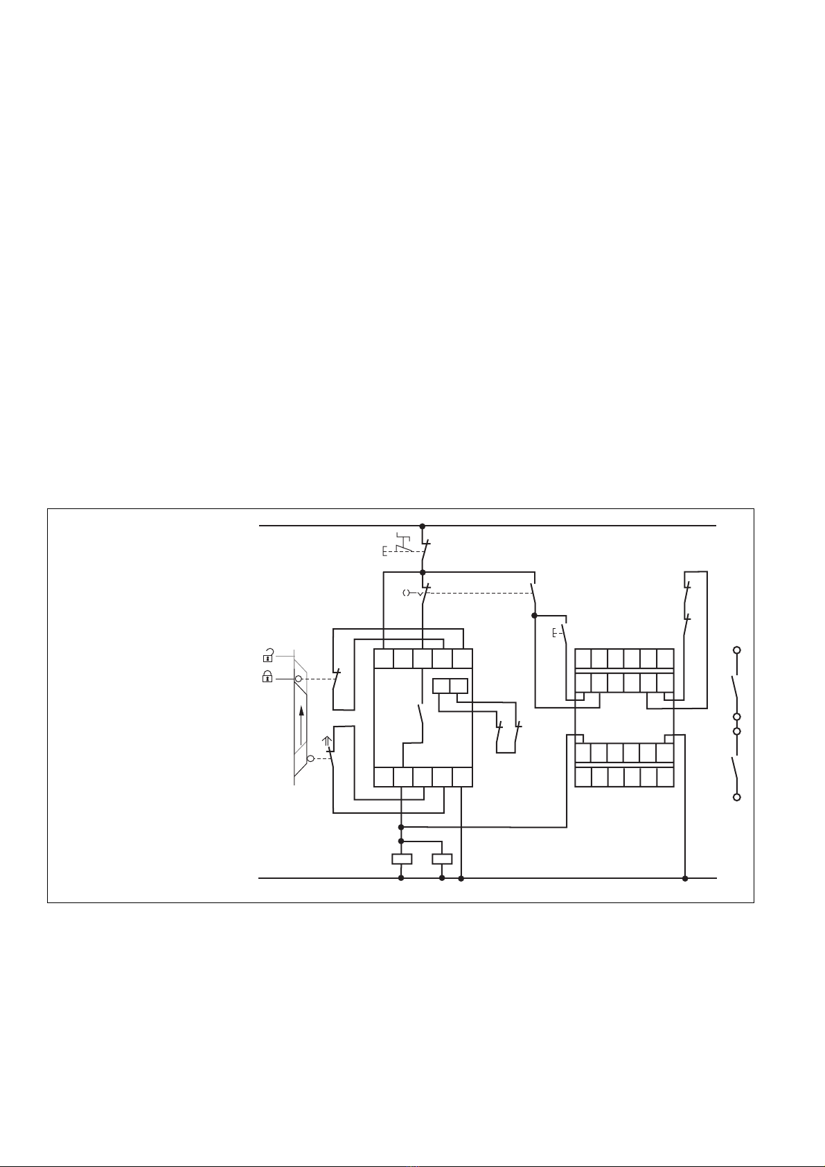
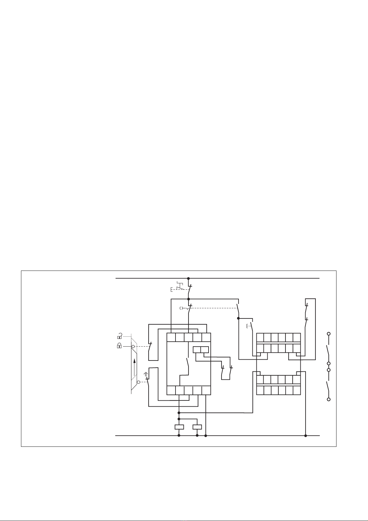
Campo de aplicación adecuado
El relé temporizador de seguridad PZW sirve
como relé de supresión (relé de impulsos)
• según EN 292 T2 párr. 3.7.10 y 4.1.4 y
EN 292 T1 párr. 3.23.8 (conmutación
paso a paso para el movimiento limitado
de partes de maquinaria que pueden
resultar peligrosas, durante los trabajos
de montaje, ajuste y posicionamiento)
• en circuitos de seguridad según
VDE 0113 y EN 60.204-1 (p.ej. con
coberturas móviles)
El dispositivo ha sido diseñado para ser
empleado con
• dispositivo de seguridad de la serie
PNOZ
• supervisor de puertas protectoras de la
serie PST
• relé de manejo a dos manos de la serie
P2HZ
La categoría realizable según EN 954-1
depende de la categoría del dispositivo
base. No puede ser rebasada por el PZW.
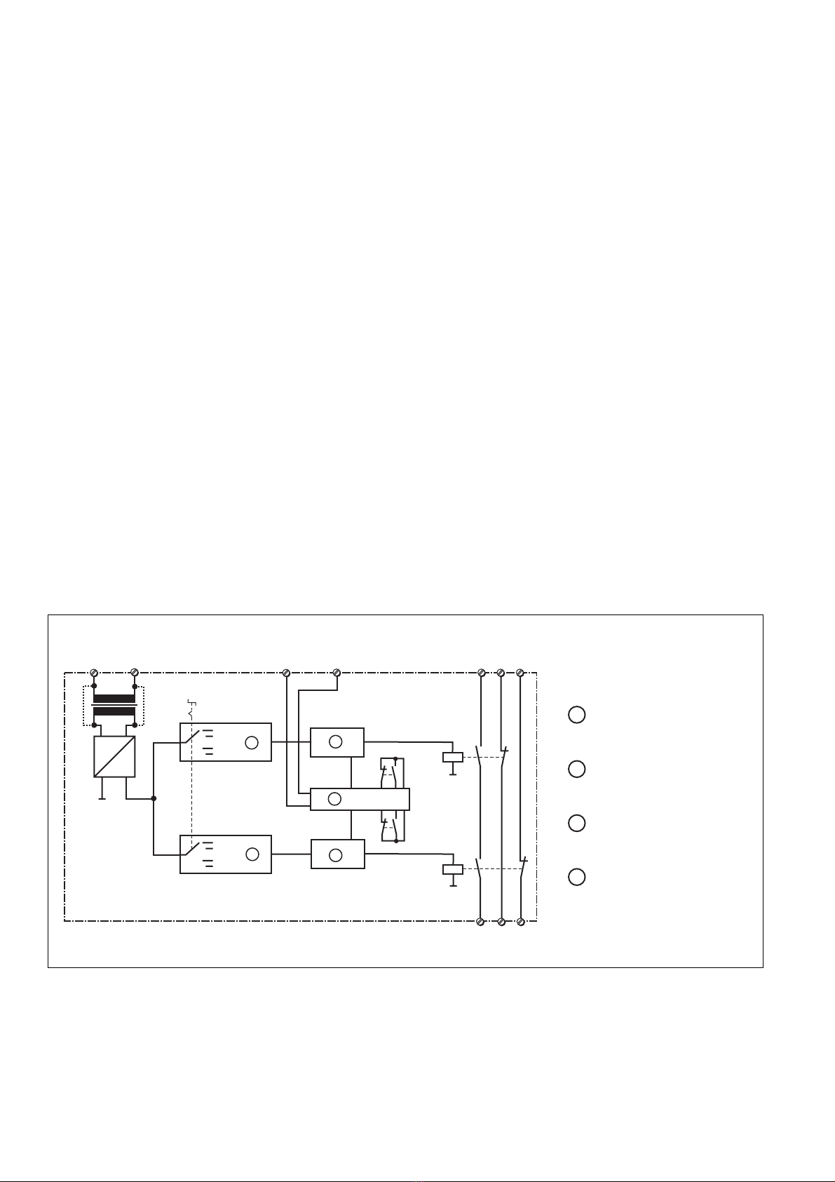
Descripción del dispositivo
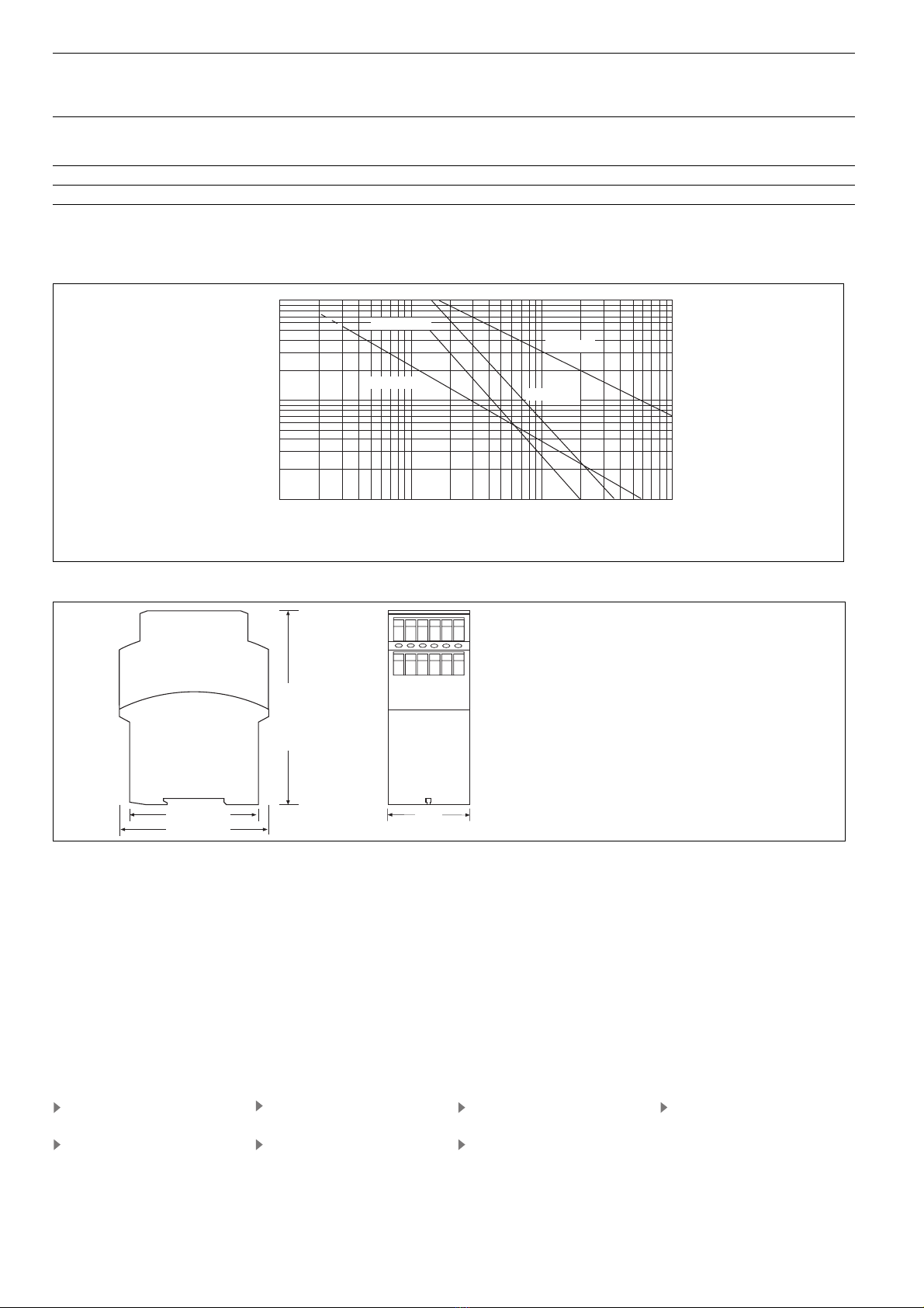
El relé temporizador de seguridad PZW se
encuentra montado dentro de una carcasa
P-97. Existen diversas variantes disponibles
para el funcionamiento con tensión alterna y
una variante para el funcionamiento con
tensión continua.
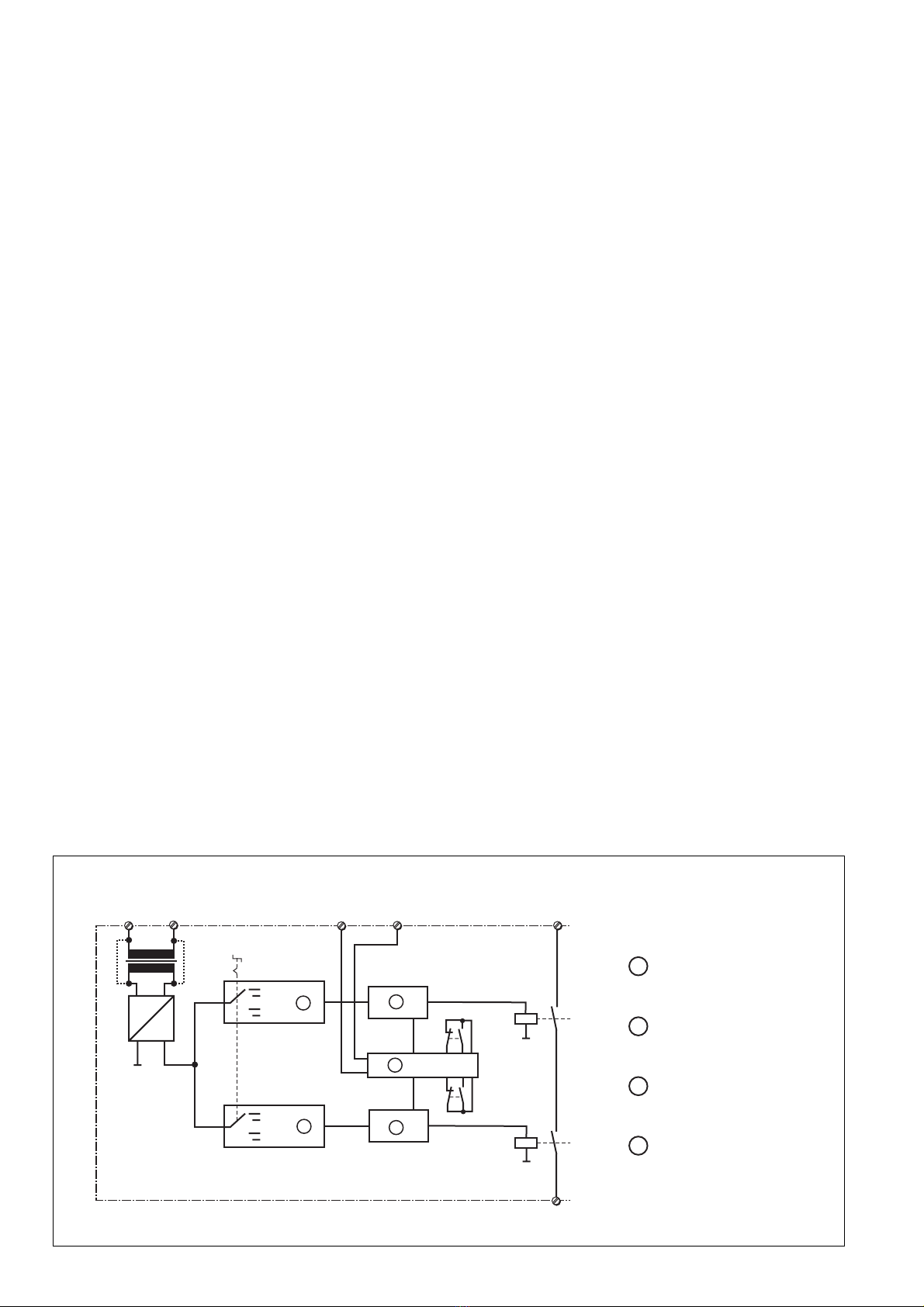
Características:
• Salidas de relé:
1 contacto de seguridad (NA), con guía
forzada
2 contactos auxiliares (NC), con guía for-
zada
Norme di sicurezza
• Il dispositivo può venire installato e mes-
so in funzione solo da persone che cono-
scono bene le presenti istruzioni per l’uso
e le disposizioni vigenti relative alla sicu-
rezza di lavoro e all’antinfortunistica. Os-
servare le disposizioni della VDE nonché
le norme locali, soprattutto per quanto
riguarda le misure preventive di protezione.
• Durante il trasporto, l’immagazzinamento
e il funzionamento attenersi alle condizio-
ni prescritte dalla norma EN 60068-2-6 (v.
"Dati tecnici").
• Se viene aperto l’alloggiamento oppure
se vengono apportate modifiche in pro-
prio decade il diritto di garanzia.
• Montare il dispositivo in un armadio elet-
trico; altrimenti la polvere e l’umidità pos-
sono pregiudicare le funzioni.
• Occorre dotare tutti i contatti di uscita dei
carichi capacitivi e induttivi con un circuito
di sicurezza sufficiente.
Uso previsto
Il relè temporizzatore di sicurezza funge da
relè a contatti striscianti (relè a impulsi)
• conformemente alla norma EN 292 T2:
1991 par. 3.7.10 e 4.1.4 e EN 292 T1:
1991 par. 3.23.8 (dispositivo di comando
per spostamenti limitati per parti di mac-
chine pericolose durante gli interventi di
montaggio, impostazione e regolazione)
• nei circuiti di sicurezza conformi alle norme
VDE 0113 e EN 60 204-1 (per es. nel
caso di protezioni mobili)
Il dispositivo è stato concepito per essere
utilizzato con un:
• dispositivo di sicurezza della serie PNOZ
• controllo del riparo mobile della serie PST
• relè con comando bimanuale della serie
P2HZ
La categoria da raggiungere secondo
EN 954-1 dipende dalla categoria del
dispositivo base. Il PZW non la può
superare.
Descrizione
Il relè temporizzatore di sicurezza PZW è
inserito in un alloggiamento P-97. Per il fun-
zionamento a corrente alternata sono dispo-
nibili diverse varianti ed una variante per il
funzionamento con corrente continua.
Caratteristiche:
• Uscite relè:
1 contatto di sicurezza (NA), con contatti
guidati
2 contatti ausiliari (NC), con contatti
guidati
Veiligheidsvoorschriften
• Het apparaat mag uitsluitend worden
geïnstalleerd en in bedrijf genomen door
personen die vertrouwd zijn met deze
gebruiksaanwijzing en met de geldende
voorschriften op het gebied van arbeids-
veiligheid en ongevallenpreventie. Neemt
u de van toepassing zijnde Europese
richtlijnen en de plaatselijke voorschriften
in acht, in het bijzonder m.b.t. veiligheids-
maatregelen.
• Neem bij transport, opslag en in bedrijf de
richtlijnen volgens EN 60068-2-6 in acht
(zie "Technische gegevens").
• Het openen van de behuizing of het ei-
genmachtig veranderen van de
schakeling heeft verlies van de garantie
tot gevolg.
• Monteert u het apparaat in een schakel-
kast. Stof en vochtigheid kunnen anders
de werking nadelig beïnvloeden.
• Zorg bij capacitieve of inductieve belas-
ting van de uitgangscontacten voor ade-
quate contactbeschermingsmaatregelen.
Gebruik volgens de voorschriften
Het veiligheidstijdrelais PZW dient als wis-
relais (impulsrelais)
• volgens EN 292 T2 art. 3.7.10 en 4.1.4 en
EN 292 T1 art. 3.23.8 (Stapsgewijze
schakeling voor begrensde beweging van
gevaarlijke machinedelen tijdens
montage, afstelling en instelling)
• in veiligheidscircuits volgens
VDE 0113 en EN 60.204-1 (b.v. bij
beweegbare afschermingen)
Het apparaat is bestemd voor gebruik met
een
• veiligheidsrelais uit de serie PNOZ
• hekbewakingsrelais uit de serie PST
• tweehandenbedieningsrelais uit de serie
P2HZ
De te realiseren categorie volgens EN 954-1
is afhankelijk van de categorie van het
basisrelais. Deze kan niet door het PZW
worden overschreden.
Apparaatbeschrijving
Het veiligheidstijdrelais PZW is in een P-97-
behuizing ondergebracht. Er zijn verschil-
lende varianten voor wisselspanning en één
variant voor gelijkspanning beschikbaar.
Kenmerken:
• Relaisuitgangen:
1 veiligheidscontact (M), mechanisch ge-
dwongen
2 hulpcontacten (V), mechanisch gedwon-
gen
19 157-05
PZW
4E Instrucciones de uso
4I Istruzioni per l`uso
4NL Gebruiksaanwijzing