Pilz PNOZ s6.1 User manual

21 692-01
PNOZ s6.1
- 1 -
4D Betriebsanleitung
4GB Operating instructions
4F Manuel d'utilisation
4E Instrucciones de uso
4I Istruzioni per l`uso
4NL Gebruiksaan ijzing
21 692-01PNOZ s6.1
Sicherheitsschaltgerät PNOZ s6.1
Das Zweihandbediengerät erfüllt die Anforde-
rungen nach EN 574 Typ IIIA. Es zwingt den Be-
diener die Hände während der
gefahrbringenden Bewegung außerhalb der
Gefahrenstelle zu halten. Es ist bestimmt für
den Einsatz in Zweihandschaltungen.
ACHTUNG!
Das Zweihandbediengerät darf nicht in
Pressensteuerungen eingesetzt werden.
Es ist nur für den Einsatz bei einer durch die
Risikoanalyse ermittelten geringen Gefähr-
dung geeignet (z.B. EN 954-1 Kat. B oder
1).
Safety relay PNOZ s6.1
The two-hand control relay meets the require-
ments of EN 574 Type IIIA. It forces the opera-
tor to keep his hands outside the danger zone
area during the hazardous movement. It is de-
signed for use in two-hand circuits.
CAUTION!
The two-hand control relay may not be
used on press controllers. It is only suita-
ble for use where the risk analysis has es-
tablished a low level of risk (e.g. EN 954-1
Cat. B or 1).
Bloc logique de sécurité PNOZ s6.1
Le relais de commande bimanuelle satisfait aux
exigences du type IIIA selon la norme EN 574.
Pendant le mouvement dangereux, le relais
oblige l'opérateur à avoir les deux mains si-
tuées en dehors de la zone de danger. Ce relais
est conçu pour une utilisation dans des com-
mandes bimanuelles.
ATTENTION !
Le relais de commande bimanuelle ne doit
pas être utilisé dans des commandes de
presses. L'utilisation de ce relais est uni-
quement recommandée lorsque le danger
déterminé par l'analyse des risques est fai-
ble (par exemple : EN 954-1 cat. B ou 1).
Zu Ihrer Sicherheit
`Installieren und nehmen Sie das Gerät nur
dann in Betrieb, wenn Sie diese Betriebsan-
leitung gelesen und verstanden haben und
Sie mit den geltenden Vorschriften über Ar-
beitssicherheit und Unfallverhütung vertraut
sind.
Beachten Sie die VDE- sowie die örtlichen
Vorschriften, insbesondere hinsichtlich
Schutzmaßnahmen
`Die Versorgungsspannung des Zweihandbe-
diengeräts darf nur nach der Ausschaltein-
richtung gemäß § 9 VBG 7n5.1/2
angeschlossen werden.
`Verlegen Sie die Verbindungskabel zwischen
dem Zweihandbediengerät und den Tastern
nicht unmittelbar neben Starkstromleitun-
gen; es können sonst induktive und kapaziti-
ve Störeinkopplungen entstehen.
`Verwenden Sie wegen der geringen Ströme
Tasterkontakte mit Goldauflage.
For your safety
`Only install and commission the unit if you
have read and understood these operating
instructions and are familiar with the applica-
ble regulations for health and safety at work
and accident prevention.
Ensure VDE and local regulations are met,
especially those relating to safety.
`The supply voltage for the two-hand relay
must only be connected after the shutdown
device in accordance with § 9 VBG 7n5.1/2.
`To avoid inductive and capacitance cou-
pling, the cables between the two-hand relay
and the pushbuttons must be run separately
to any power cables.
`On account of the low currents you should
use gold-plated pushbutton contacts.
Pour votre sécurité
`Vous n'installerez l'appareil et ne le mettrez
en service qu'après avoir lu et compris le
présent manuel d'utilisation et vous être fa-
miliarisé avec les prescriptions en vigueur
sur la sécurité du travail et la prévention des
accidents.
Respectez les normes locales ou VDE, parti-
culièrement en ce qui concerne la sécurité
`La tension d'alimentation du relais de com-
mande bimanuelle doit être conforme aux
prescriptions du § 9 VBG 7n5.1/2.
`Pour éviter des interférences inductives ou
capacitives, il est préférable de placer le câ-
ble reliant le relais de commande bimanuelle
aux organes de commande loin des câbles
de puissance.
`Utilisez des boutons poussoirs avec des
contacts dorés en raison des faibles intensi-
tés commutées.
Gerätemerkmale
`Relaisausgänge zwangsgeführt:
– 3 Sicherheitskontakte (S) unverzögert
– 1 Hilfskontakt (Ö) unverzögert
`1 Halbleiterausgang
`Anschlussmöglichkeiten für:
– 2 Bedienelemente (Taster)
`1 Kontakterweiterungsblock PNOZsigma
über Verbindungsstecker anschließbar
`LED-Anzeige für:
– Versorgungsspannung
– Eingangszustand Kanal 1
– Eingangszustand Kanal 2
– Schaltzustand Sicherheitskontakte
– Rückführkreis
–Fehler
`Steckbare Anschlussklemmen (wahlweise
Federkraftklemme oder Schraubklemme)
Unit features
`Positive-guided relay outputs:
– 3 safety contacts (N/O), instantaneous
– 1 auxiliary contact (N/C), instantaneous
`1 semiconductor output
`Connection options for:
– 2 operator elements (buttons)
`A connector can be used to connect 1
PNOZsigma contact expander module
`LED indicator for:
– Supply voltage
– Input status, channel 1
– Input status, channel 2
– Switch status, safety contacts
– Feedback loop
–Fault
`Plug-in connection terminals (either cage
clamp terminal or screw terminal)
Caractéristiques de l'appareil
`Sorties de relais à contact lié :
– 3 contacts de sécurité (F) instantanés
– 1 contact d'information (O) instantané
`1 sortie statique
`Raccordements possibles pour :
– 2 éléments de commande (poussoir)
`Un bloc d'extension de contacts PNOZsig-
ma raccordable par l'intermédiaire d'un con-
necteur enfichable
`LED de visualisation pour :
– Tension d'alimentation
– Etat d'entrée canal 1
– Etat d'entrée canal 2
– Etat de commutation des contacts de sé-
curité
–bouclederetour
– Erreurs
`Borniers débrochables (au choix avec rac-
cordement à ressort ou à vis)

- 2 -
Sicherheitseigenschaften
Das Zweihandbediengerät erfüllt folgende Si-
cherheitsanforderungen:
`Das Zweihandbediengerät verhindert in fol-
genden Fällen die Freigabe der Anlage:
– Spannungsausfall
–Ausfalleines Bauteils
– Kurzschluss eines Eingangskreises
– Spulendefekt
–Leiterbruch
– Erdschluß
`Überprüfung bei jedem Ein-Aus-Zyklus, ob
die Ausgangsrelais des Sicherheitsgeräts
richtig öffnen und schließen
`Das Gerät hat eine elektronische Sicherung.
Safety features
The two-hand control relay meets the following
safety requirements:
`The two-hand control relay prevents the
plant from being enabled in the following
cases:
– Power supply failure
– Component failure
– Short circuit on an input circuit
–Coildefect
– Open circuit
–Earthfault
`In each on-off cycle, the output relays on the
safety device are tested to ensure they open
and close correctly
`The unit has an electronic fuse.
Caractéristiques de sécurité
Le relais de commande bimanuelle satisfait aux
exigences de sécurité suivantes :
`Dans les cas suivants, le relais de comman-
de bimanuelle empêche la validation de l'ins-
tallation :
– coupure de courant
– panne d'un composant
– court-circuit sur un circuit d'entrée
– défaut sur la bobine
– rupture de câble
– mise à la terre
`Le bon fonctionnement des relais internes
est contrôlé automatiquement à chaque cy-
cle marche/arrêt de la machine
`L'appareil est équipé d'une sécurité électro-
nique.
Blockschaltbild/Klemmenbelegung Block diagram/terminal configuration Schéma de principe/affectation des
bornes
*nur bei UB = 48 – 240 V AC/DC *only with UB = 48 – 240 VAC/DC * uniquement lorsque UB = 48 – 240 V AC/DC
Mitte: Frontansicht mit Abdeckung
Rechts: Frontansicht ohne Abdeckung
Centre: Front view with cover
Right: Front view without cover
Schéma du milieu : vue frontale avec capot de
protection
A droite : vue frontale sans capot de protection
Funktionsbeschreibung
`Das Zweihandbediengerät muss durch
gleichzeitiges Betätigen von zwei Tastern in-
nerhalb von 0,5 s aktiviert werden. Es unter-
bricht bei Loslassen eines oder beider Taster
den Steuerbefehl für die gefährliche Bewe-
gung.
`Wieder aktivieren: Die Ausgangsrelais spre-
chen erst dann wieder an, wenn beide Bedie-
nelemente losgelassen und erneut
gleichzeitig betätigt werden.
Function description
`The two-hand control relay must be activat-
ed by simultaneously pressing two buttons
within 0,5 s. If one or both of the buttons are
released, the unit interrupts the control com-
mand for the hazardous movement.
`Reactivation: The output relays will not re-
energise until both operator elements have
been released and then re-operated simulta-
neously.
Description du fonctionnement
`Le relais de commande bimanuelle doit être
activé par l'appui simultané de deux boutons
pendant 0,5 s. Il interrompt l'ordre de com-
mande du mouvement dangereux lorsque
l'un des deux boutons ou les deux boutons
sont relâchés.
`Nouvelle commande : les relais de sortie ne
peuvent être réenclenchés que lorsque les
deux éléments de commande ont été relâ-
chés puis de nouveau actionnés ensemble.
InputInput
A1 A2 S23 S24
=
Po er
Feed-
back
(Reset)
S34
S13 S14
=
Y32
(~)*
K1
K2
13 23 33
24 34
14
41
42
Interface
expansion
unit
( )*

- 3 -
Montage
Grundgerät ohne Kontakterweiterungs-
block montieren:
`Stellen Sie sicher, dass der Abschlussstek-
ker seitlich am Gerät gesteckt ist.
Grundgerät und Kontakterweiterungsblock
PNOZsigma verbinden:
`Entfernen Sie den Abschlussstecker seitlich
am Grundgerät und am Kontakterweite-
rungsblock.
`Verbinden Sie das Grundgerät und den Kon-
takterweiterungsblock mit dem mitgeliefer-
ten Verbindungsstecker bevor Sie die Geräte
auf der Normschiene montieren.
Montage im Schaltschrank
`Montieren Sie das Sicherheitsschaltgerät in
einen Schaltschrank mit einer Schutzart von
mindestens IP54.
`Befestigen Sie das Gerät mit Hilfe des Rast-
elements auf der Rückseite auf einer Norm-
schiene.
`Sichern Sie das Gerät auf einer senkrechten
Normschiene (35 mm) durch ein Halte-
element (z. B. Endhalter oder Endwinkel).
`Vor dem Abheben von der Normschine das
Gerät nach oben oder unten schieben.
Montage
Install base unit without contact expander
module:
`Ensure that the plug terminator is inserted at
the side of the unit.
Connect base unit and PNOZsigma contact
expander module:
`Remove the plug terminator at the side of the
base unit and at the contact expander mod-
ule.
`Connect the base unit and the contact ex-
pander module to the supplied connector
before mounting the units to the DIN rail.
Installation in control cabinet
`The safety relay should be installed in a con-
trol cabinet with a protection type of at least
IP54.
`Use the notch on the rear of the unit to attach
it to a DIN rail.
`Ensure the unit is mounted securely on a ver-
tical DIN rail (35 mm) by using a fixing ele-
ment (e.g. retaining bracket or an end angle).
`Push the unit upwards or downwards before
lifting it from the DIN rail.
Montage
Installer l'appareil de base sans bloc d'ex-
tension de contacts :
`Assurez-vous que la fiche de terminaison est
insérée sur le côté de l'appareil.
Raccorder l'appareil de base et le bloc d'ex-
tension de contacts PNOZsigma
`Retirez la fiche de terminaison sur le côté de
l'appareil de base et sur le bloc d'extension
de contacts.
`Avant de monter les appareils sur le rail DIN,
reliez l'appareil de base et le bloc d'exten-
sion de contacts à l'aide du connecteur four-
ni.
Montage dans une armoire
`Montez le bloc logique de sécurité dans une
armoire électrique ayant un indice de protec-
tion d'au moins IP54.
`Montez l'appareil sur un rail DIN à l'aide du
système de fixation situé sur la face arrière.
`Fixez l'appareil monté sur un rail DIN vertical
(35 mm) à l'aide d'un élément de maintien
(par exemple : un support terminal ou une
équerre terminale).
`Avant de retirer l'appareil du rail DIN, pous-
sez l'appareil vers le haut ou vers le bas.
Verdrahtung
Beachten Sie:
`Angaben im Abschnitt „Technische Daten“
unbedingt einhalten.
`Die Ausgänge 13-14, 23-24, 33-34 sind
Sicherheitskontakte, der Ausgang 41-42
ist ein Hilfskontakt (z. B. für Anzeige).
`Vor die Ausgangskontakte eine Sicherung
(s. techn. Daten) schalten, um das Ver-
schweißen der Kontakte zu verhindern.
`Berechnung der max. Leitungslänge Imax im
Eingangskreis:
Rlmax = max. Gesamtleitungswiderstand
(s. techn. Daten)
Rl/ km = Leitungswiderstand/km
`Leitungsmaterial aus Kupferdraht mit einer
Temperaturbeständigkeit von 60/75 °C ver-
wenden.
`Sorgen Sie an allen Ausgangskontakten bei
kapazitiven und induktiven Lasten für eine
ausreichende Schutzbeschaltung.
Wiring
Please note:
`Information given in the “Technical details”
must be followed.
`Outputs 13-14, 23-24, 33-34 are safety
contacts, output 41-42 is an auxiliary con-
tact (e.g. for display).
`To prevent contact welding, a fuse should be
connected before the output contacts (see
technical details).
`Calculation of the max. cable runs lmax in the
input circuit:
Rlmax = max. overall cable resistance (see
technical details)
Rl/km = cable resistance/km
`Use copper wire that can withstand 60/75
°C.
`Sufficient fuse protection must be provided
on all output contacts with capacitive and in-
ductive loads.
Raccordement
Important :
`Respectez impérativement les données indi-
quées dans la partie "Caractéristiques tech-
niques".
`Les sorties 13-14, 23-24, 33-34 sont des
contacts de sécurité, la sortie 41-42 est
un contact d'information (par exemple pour
l'affichage).
`Protection des contacts de sortie par des fu-
sibles (voir les caractéristiques techniques)
pour éviter leur soudage.
`Calcul de la longueur de câble max. Imax sur
le circuit d'entrée :
Rlmax = résistance max. de l'ensemble du
câblage (voir les caractéristiques techni-
ques)
Rl/km = résistance du câblage/km
`Utilisez uniquement des fils de câblage en
cuivre résistant à des températures de 60/
75 °C.
`Assurez-vous du pouvoir de coupure des
contacts de sortie en cas de charges capaci-
tives ou inductives.
Betriebsbereitschaft herstellen Preparing for operation Mettre l'appareil en mode de marche
Anschluss Connection Connexion
`Versorgungsspannung `Supply voltage `Tension d'alimentation
Versorgungsspannung/power supply/tension
d'alimentation
AC DC
`Eingangskreis `Input circuit `Circuit d'entrée
Eingangskreis/input circuit/circuit d'entrée Einkanalig/single-channel /monocanal Zweikanalig/dual-channel/à deux canaux
Zweihandtaster
mit Querschlusserkennung/
two-hand button
with detection of shorts across contacts/
poussoir de commande bimanuelle
avec détection des courts-circuits entre les
canaux
Rlmax
Rl / km
Imax = Rlmax
Rl / km
Imax =
Rlmax
Rl / km
Imax =
A1 L
A2 N
S14
A1 L+
A2 L-
S23
S13
S14
S24
S1
S2

- 4 -
`Rückführkreis `Feedback loop `boucle de retour
Rückführkreis/
feedback loop/
boucle de retour
Rückführkreis/feedback loop/ boucle de retour
`Halbleiterausgang `Semiconductor output `Sortie statique
Betrieb
Das Gerät ist betriebsbereit, wenn die LED Po-
wer permanent leuchtet.
LEDs zeigen den Status und Fehler während
des Betriebs an:
LED leuchtet
LED blinkt
INFO
Statusanzeigen und Fehleranzeigen kön-
nen unabhängig voneinander auftreten. Bei
einer Fehleranzeige leuchtet oder blinkt die
LED "Fault" (Ausnahme: "Versorgungs-
spannung zu gering"). Eine zusätzlich blin-
kende LED weist auf eine mögliche
Fehlerursache hin. Eine zusätzlich statisch
leuchtende LED weist auf einen normalen
Betriebszustand hin. Es können mehrere
Statusanzeigen und Fehleranzeigen gleich-
zeitig auftreten.
Operation
The unit is ready for operation when the Power
LED is permanently lit.
LEDs indicate the status and errors during op-
eration:
LED on
LED flashes
INFORMATION
Status indicators and error indicators may
occur independently. In the case of an error
display, the "Fault" LED will light or flash
(exception: "Supply voltage too low"). An
LED that is also flashing indicates the po-
tential cause of the error. An LED that is lit
and is static indicates a normal operating
status. Several status indicators and error
indicators may occur simultaneously.
Utilisation
L'appareil est prêt à fonctionner lorsque la LED
Power reste allumée en permanence.
Les LEDs indiquent l'état et les erreurs lors du
fonctionnement:
LED allumée
LED clignotante
INFORMATION
L'affichage de l'état et des erreurs peut sur-
venir indépendamment. Lors de l'affichage
d'une erreur, la LED "Fault" s'allume ou cli-
gnote (exception : "Tension d'alimentation
trop faible"). Une LED clignotante supplé-
mentaire informe sur une cause possible
d'erreur. Une LED supplémentaire qui s'al-
lume de façon permanente informe de l'état
normal de fonctionnement. Plusieurs affi-
chages de l'état et des erreurs peuvent sur-
venir en même temps.
Statusanzeigen Status indicators Affichages d'état
Power
Versorgungsspannung liegt an.
Power
Supply voltage is present.
Power
la tension d'alimentation est présente.
In1
Taster an S11 ist betätigt.
In1
Pushbutton on S11 is operated.
In1
Le poussoir sur S11 est actionné.
In2
Taster an S21 ist betätigt.
In2
Pushbutton on S21 is operated.
In2
Le poussoir sur S21 est actionné.
Out
Sicherheitskontakte sind geschlossen und
Halbleiterausgang Y32 führt High-Signal.
Out
Safety contacts are closed and semicon-
ductor output Y32 carries a high signal.
Out
Les contacts de sécurité sont fermés et la
sortie statique Y32 délivre un niveau haut.
Reset
An S34 liegt 24 V DC an.
Reset
24 VDC is present at S34.
Réarmement
24 V DC sur S34.
Fehleranzeigen Fault indicators Affichage des erreurs
Alle LEDs aus
Diagnose: Querschluss/Erdschluss; Gerät
ausgeschaltet
`Abhilfe: Querschluss/Erdschluss behe-
ben, Versorgungsspannung für 1 Min.
ausschalten.
All LEDs off
Diagnostics: Short across contacts/earth
fault; unit switched off
`Remedy: Rectify short across contacts/
earth fault, switch off supply voltage for 1
min.
Toutes les LEDs sont éteintes
Diagnostic : court-circuit/mise à la terre ;
appareil éteint
`Remède : supprimer le court-circuit/la
mise à la terre, couper la tension d'ali-
mentation pendant 1 min.
Fault
Diagnose: Abschlussstecker nicht gesteckt
`Abhilfe: Abschlussstecker stecken, Ver-
sorgungsspannung aus- und wieder ein-
schalten.
Fault
Diagnostics: Plug terminator not connected
`Remedy: Insert plug terminator, switch
supply voltage off and then on again.
Fault
Diagnostic : fiche de terminaison non bran-
chée
`Remède : brancher la fiche de terminai-
son, couper puis remettre en marche la
tension d'alimentation
Fault
Diagnose: Interner Fehler, Gerät defekt
`Abhilfe: Versorgungsspannung aus- und
wieder einschalten, gegebenenfalls Ge-
rät tauschen.
Fault
Diagnostics: Internal error, unit defective
`Remedy: Switch supply voltage off and
then on again, change unit if necessary.
Fault
Diagnostic : erreur interne, appareil défec-
tueux
`Remède : couper puis remettre en mar-
che la tension d'alimentation, si besoin
échanger l'appareil
Power
Diagnose: Versorgungsspannung zu gering
`Abhilfe: Versorgungsspannung überprü-
fen.
Power
Diagnostics: Supply voltage too low
`Remedy: Check the supply voltage.
Power
Diagnostic : tension d'alimentation trop fai-
ble
`Remède : vérifier la tension d'alimenta-
tion
K5 K6
K5 L1
N
K6
S24
13 (23,33)
S34
14 (24,34)
S24
S34
Y32 PLC Input
S14 Gnd

- 5 -
In1, In2 wechselweise
Fault
Diagnose: Anschlussfehler oder Quer-
schluss zwischen S12 und S22 erkannt
oder interner Fehler
`Abhilfe: Anschlussfehler beheben oder
Querschluss beheben, Versorgungs-
spannung aus- und wieder einschalten.
In1, In2 alternately
Fault
Diagnostics: Connection error or short be-
tween S12 and S22 detected or internal er-
ror
`Remedy: Rectify connection error or
short across contacts, switch supply
voltage off and then on again.
In1, In2 alternativement
Fault
Diagnostic : détection d'une erreur de rac-
cordement ou d'un court-circuit entre S12
et S22 ou erreur interne
`Remède : supprimer l'erreur de raccor-
dement ou le court-circuit, couper puis
remettre en marche la tension d'alimen-
tation.
In1
Fault
Diagnose: Gleichzeitigkeitsüberschrei-
tung: Kanal 1 zu spät oder Einschaltblocka-
de wegen Kurzzeitunterbrechung an S11;
Eingangskreise nicht gleichzeitig betätigt
`Abhilfe: Beide Eingangskreise, S12 und
S22 gleichzeitig öffnen und wieder
schließen.
In1
Fault
Diagnostics: Simultaneity exceeded: Chan-
nel 1 too late or power-up blocked due to
short-term interruption at S11; input cir-
cuits not operated simultaneously
`Remedy: Open both input circuits, S12
and S22, simultaneously and then close
again.
In1
Fault
Diagnostic : dépassement de la
simultanéité : canal 1 en retard ou blocage
du relais à cause d'une coupure aléatoire
sur S11 ; les circuits d'entrée ne sont pas
actionnés simultanément
`Remède : ouvrir ensemble les deux cir-
cuits d'entrée S12 et S22 puis les refer-
mer.
In2
Fault
Diagnose: Gleichzeitigkeitsüberschrei-
tung: Kanal 2 zu spät oder Einschaltblocka-
de wegen Kurzzeitunterbrechung an S21;
Eingangskreise nicht gleichzeitig betätigt
`Abhilfe: Beide Eingangskreise, S12 und
S22 gleichzeitig öffnen und wieder
schließen.
In2
Fault
Diagnostics: Simultaneity exceeded: Chan-
nel 2 too late or power-up blocked due to
short-term interruption at S21; input cir-
cuits not operated simultaneously
`Remedy: Open both input circuits, S12
and S22, simultaneously and then close
again.
In2
Fault
Diagnostic : dépassement de la
simultanéité : canal 2 en retard ou blocage
du relais à cause d'une coupure aléatoire
sur S21 ; les circuits d'entrée ne sont pas
actionnés simultanément
`Remède : ouvrir ensemble les deux cir-
cuits d'entrée S12 et S22 puis les refer-
mer.
Fehler - Störungen
`Fehlfunktionen der Kontakte: Bei ver-
schweißten Kontakten ist nach Öffnen des
Eingangskreises keine neue Aktivierung
möglich.
Faults - malfunctions
`Contact malfunctions: If the contacts have
welded, reactivation will not be possible after
the input circuit has opened.
Erreurs – Défaillances
`Défaut de fonctionnement des contacts de
sortie : si les contacts sont soudés, un réar-
mement est impossible après ouverture du
circuit d'entrée.
Technische Daten Technical details Caractéristiques techniques
Elektrische Daten Electrical data Données électriques
Versorgungsspannung Supply voltage Tension d'alimentation
Versorgungsspannung UBDC Supply voltage UBDC Tension d'alimentation UBDC 24 V
Versorgungsspannung UBAC/DC Supply voltage UBAC/DC Tension d'alimentation UBAC/DC 48 - 240 V
Spannungstoleranz Voltage tolerance Plage de la tension d'alimentation -15 %/+10 %
Leistungsaufnahme bei UBAC Power consumption at UBAC Consommation UBAC 7,0 VA
Leistungsaufnahme bei UBDC Power consumption at UBDC Consommation UBDC 3,5 W
Frequenzbereich AC Frequency range AC Plage de fréquences AC 50 - 60 Hz
Restwelligkeit DC Residual ripple DC Ondulation résiduelle DC 20 %
Spannung und Strom an Voltage and current at Tension et courant sur
Eingangskreis DC: 24,0 V Input circuit DC: 24,0 V circuit d'entrée DC : 24,0 V
Schließer N/O contact Contact à fermeture 20 mA
Rückführkreis DC: 24,0 V Feedback loop DC: 24,0 V boucle de retour DC : 24,0 V 15,0 mA
Anzahl der Ausgangskontakte Number of output contacts Nombre de contacts de sortie
Sicherheitskontakte (S)
unverzögert:
Safety contacts (S) instantaneous: Contacts de sécurité (F)
instantanés :
3
Hilfskontakte (Ö): Auxiliary contacts (N/C): Contacts d'information (O) : 1
Kategorie der Ausgangskontakte
nach EN 954-1 Category of output contacts in ac-
cordance with EN 954-1 Catégorie des contacts de sortie
selon EN 954-1
Sicherheitskontakte (S) unverzö-
gert:
Safety contacts (S) instantaneous: Contacts de sécurité (F)
instantanés :
1

- 6 -
Gebrauchskategorie nach
EN 60947-4-1 Utilisation category in accordance
with EN 60947-4-1 Catégorie d'utilisation selon
EN 60947-4-1
Sicherheitskontakte: AC1 bei 240 V Safety contacts: AC1 at 240 V Contacts de sécurité : AC1
pour 240 V Imin:0,01 A ,
Imax:U
B = 48 - 240 V AC/DC:
6,0 A, UB = 24 V DC: 8,0 A
Pmax: UB = 48 - 240 V AC/DC:
1500 VA, UB = 24 V DC: 2000 VA
Sicherheitskontakte: DC1 bei 24 V Safety contacts: DC1 at 24 V Contacts de sécurité : DC1 pour
24 VImin: 0,01 A , Imax: UB = 48 - 240
V AC/DC: 6,0 A,
UB = 24 V DC: 8,0 A
Pmax:
UB = 48 - 240 V AC/DC: 150 W,
UB = 24 V DC: 200 W
Hilfskontakte: AC1 bei 240 V Auxiliary contacts: AC1 at 240 V Contacts d'information : AC1
pour 240 V Imin: 0,01 A ,
Imax: UB = 48 - 240 V AC/DC:
6,0 A, UB = 24 V DC: 8,0 A
Pmax:
UB = 48 - 240 V AC/DC:
1500 VA, UB = 24 V DC: 2000 VA
Hilfskontakte: DC1 bei 24 V Auxiliary contacts: DC1 at 24 V Contacts d'information : DC1
pour 24 V Imin: 0,01 A ,
Imax: UB = 48 - 240 V AC/DC:
6,0 A, UB = 24 V DC: 8,0 A
Pmax:
UB = 48 - 240 V AC/DC: 150 W,
UB = 24 V DC: 200 W
Gebrauchskategorie nach
EN 60947-5-1 Utilisation category in accordance
with EN 60947-5-1 Catégorie d'utilisation selon
EN 60947-5-1
Sicherheitskontakte: AC15 bei
230 VSafety contacts: AC15 at 230 V Contacts de sécurité : AC15
pour 230 V Imax:
UB = 48 - 240 V AC/DC: 3,0 A,
UB = 24 V DC: 6,0 A
Sicherheitskontakte: DC13 bei 24 V
(6 Schaltspiele/min)
Safety contacts: DC13 at 24 V (6
cycles/min)
Contacts de sécurité : DC13
pour 24 V (6 manœuvres/min)
Imax:
UB = 48 - 240 V AC/DC: 4,0 A,
UB = 24 V DC: 5,0 A
Hilfskontakte: AC15 bei 230 V Auxiliary contacts: AC15 at 230 V Contacts d'information : AC15
pour 230 V Imax:
UB = 48 - 240 V AC/DC: 3,0 A
UB = 24 V DC: 6,0 A
Hilfskontakte: DC13 bei 24 V (6
Schaltspiele/min)
Auxiliary contacts: DC13 at 24 V (6
cycles/min)
Contacts d'information : DC13
pour 24 V (6 manœuvres/min)
Imax:
UB = 48 - 240 V AC/DC: 4,0 A
UB = 24 V DC: 5,0 A
Kontaktmaterial Contact material Matériau des contacts AgCuNi + 0,2 µm Au
Kontaktabsicherung, extern (IK= 1
kA) nach EN 60947-5-1 External contact fuse protection (IK
= 1 kA) to EN 60947-5-1 Protection des contacts en externe
(IK= 1 kA) selon EN 60947-5-1
Schmelzsicherung flink Blow-out fuse, quick Fusible rapide
Sicherheitskontakte: Safety contacts: Contacts de sécurité : UB = 48 - 240 V AC/DC: 6 A,
UB = 24 V DC: 10 A
Hilfskontakte: Auxiliary contacts: Contacts d'information : UB = 48 - 240 V AC/DC: 6 A,
UB = 24 V DC: 10 A
Schmelzsicherung träge Blow-out fuse, slow Fusible normal
Sicherheitskontakte: Safety contacts: Contacts de sécurité : UB = 48 - 240 V AC/DC: 4 A
UB = 24 V DC: 6 A
Hilfskontakte: Auxiliary contacts: Contacts d'information : UB = 48 - 240 V AC/DC: 4 A
UB = 24 V DC: 6 A
Sicherungsautomat 24V AC/DC,
Charakteristik B/C
Circuit breaker 24 VAC/DC, charac-
teristic B/C
Disjoncteur 24 V AC/DC, caractéris-
tique B/C
Sicherheitskontakte: Safety contacts: Contacts de sécurité : UB = 48 - 240 V AC/DC: 4 A
UB = 24 V DC: 6 A
Hilfskontakte: Auxiliary contacts: Contacts d'information : UB = 48 - 240 V AC/DC: 4 A
UB = 24 V DC: 6 A
Halbleiterausgänge (kurz-
schlussfest)
Semiconductor outputs (short cir-
cuit proof)
Sorties statiques (protégées contre
les courts-circuits)
24,0 V DC, 20 mA
Max. Gesamtleitungswiderstand
Rlmax je Eingangskreis
Max. overall cable resistance
Rlmax per input circuit
Résistance max. de l'ensemble du
câblage Rlmax pour chaque circuit
d'entrée
30 Ohm
Sicherheitstechnische Kennda-
ten Safety-related characteristic
data Caractéristiques techniques de
sécurité
Wahrscheinlichkeit eines gefahr-
bringenden Ausfalls pro Stunde
(PFHD)
Probability of dangerous failure per
hour (PFHD)
Probabilité d'apparition d'une dé-
faillance dangereuse par heure
(PFHD)
Sicherheitskontakte unverzögert Safety contacts, instantaneous Contacts de sécurité instantanés 2,44E-09 1/h
SIL-Anspruchsgrenze (SIL CL) SIL claim limit (SIL CL) Limite de revendication SIL (SIL CL)
Sicherheitskontakte unverzögert Safety contacts, instantaneous Contacts de sécurité instantanés 3
Elektrische Daten Electrical data Données électriques

- 7 -
Performance Level (PL) Performance level (PL) Niveau de performance (PL)
Sicherheitskontakte unverzögert Safety contacts, instantaneous Contacts de sécurité instantanés e
Proof-Test-Intervall in Jahren Proof test interval in years Intervalle du test périodique en an-
nées
20
Zeiten Times Temporisations
Rückfallverzögerung (Ansprechzeit
nach EN 574)
Delay-on de-energisation (reaction
time in accordance with EN 574)
Temps de retombée (temps d'appel
selon l'EN 574)
Schließer N/O contact Contact à fermeture 40 ms
Öffner N/C contact Contact à ouverture 50 ms
Wiederbereitschaftszeit Recovery time Temps de réinitialisation 250 ms
Gleichzeitigkeit Kanal 1 und 2 Simultaneity, channel 1 and 2 Simultanéité des canaux 1 et 2 0,5 s
Überbrückung bei Spannungsein-
brüchen der Versorgungsspannung
Supply interruption before de-ener-
gisation
Inhibition en cas de micro-coupures
de la tension d'alimentation
20 ms
Umweltdaten Environmental data Données sur l'environnement
EMV EMC CEM EN 60947-5-1, EN 61000-6-2,
EN 61000-6-4
Schwingungen nach EN 60068-2-6 Vibration to EN 60068-2-6 Vibrations selon EN 60068-2-6
Frequenz Frequency Fréquence 10 - 55 Hz
Amplitude Amplitude Amplitude 0,35 mm
Klimabeanspruchung Climatic suitability Sollicitations climatiques EN 60068-2-78
Luft- und Kriechstrecken Airgap creepage Cheminement et claquage EN 60947-1
Bemessungsisolationsspannung Rated insulation voltage Tension assignée d'isolement 250 V
Bemessungsstoßspannungsfestig-
keit
Rated impulse withstand voltage Tension assignée de tenue aux
chocs
4,0 kV
Umgebungstemperatur Ambient temperature Température d'utilisation -10 - 55 °C
Lagertemperatur Storage temperature Température de stockage -40 - 85 °C
Schutzart Protection type Indice de protection
Einbauraum (z. B. Schaltschrank) Mounting (e.g. cabinet) Lieu d'implantation (par exemple :
armoire électrique)
IP54
Gehäuse Housing Boîtier IP40
Klemmenbereich Terminals Borniers IP20
Mechanische Daten Mechanical data Données mécaniques
Gehäusematerial Housing material Matériau du boîtier
Gehäuse Housing Boîtier PC
Front Front Face avant PC
Max. Querschnitt des Außenleiters
bei Schraubklemmen
Max. cross section of external con-
ductors with screw terminals
Capacité de raccordement des bor-
niers à vis
1 Leiter flexibel 1 core flexible 1 câble flexible 0,25 - 2,50 mm² , 24 - 12 AWG
2 Leiter gleichen Querschnitts, flexi-
bel:
2 core, same cross section, flexible: 2 câbles flexibles de même
section :
mit Aderendhülse, ohne Kunststoff-
hülse
with crimp connectors, without in-
sulating sleeve
avec embout, sans cosse plastique 0,25 - 1,00 mm² , 24 - 16 AWG
ohne Aderendhülse oder mit TWIN
Aderendhülse
without crimp connectors or with
TWIN crimp connectors
sans embout ou avec embout TWIN 0,20 - 1,50 mm² , 24 - 16 AWG
Anzugsdrehmoment bei Schraub-
klemmen
Torque setting with screw terminals Couple de serrage des borniers à
vis
0,50 Nm
Max. Querschnitt des Außenleiters
bei Käfigzugfederklemmen/Feder-
kraftklemmen: flexibel ohne Ade-
rendhülse
Max. cross section of external con-
ductors with cage clamp terminals/
spring-loaded terminals: Flexible
without crimp connectors
Capacité de raccordement des bor-
niers à ressort : flexible sans em-
bout
0,20 - 2,50 mm² , 24 - 12 AWG
Käfigzugfederklemmen/Federkraft-
klemmen: Klemmstellen pro An-
schluss
Cage clamp terminals/spring-load-
ed terminals: Terminal points per
connection
Borniers à ressort :points de rac-
cordement pour chaque borne
2
Abisolierlänge Stripping length Longueur dénudation 9 mm
Abmessungen Dimensions Dimensions
Höhe (Schraubklemmen) Height (screw terminals) Hauteur (borniers à vis) 98,0 mm
Höhe (Federkraftklemmen) Height (cage clamp terminals) Hauteur (borniers à ressort) 100,0 mm
Breite Width Largeur 22,5 mm
Tiefe Depth Profondeur 120,0 mm
Gewicht Weight Poids UB = 24 V DC: 190 g,
UB = 48 - 240 V AC/DC: 210 g
Es gelten die 2006-07 aktuellen Ausgaben der
Normen.
The standards current on 2006-07 apply. Les versions actuelles 2006-07 des normes
s'appliquent.
Konventioneller thermischer
Strom Conventional thermal current Courant thermique convention-
nel
Anzahl der Kontakte Number of contacts Nombre de contacts Ith (A) pro Kontakt bei UBAC/DC
111U
B = 48 - 240 V AC/DC: 6,00 A
UB = 24 V DC: 8,00 A
Sicherheitstechnische Kennda-
ten Safety-related characteristic
data Caractéristiques techniques de
sécurité

21 692-01, 2006-12Printed in Germany
21 692-012006-11Printed in Germany
222U
B = 48 - 240 V AC/DC: 6,00 A
UB = 24 V DC: 8,00 A
333U
B = 48 - 240 V AC/DC: 4,50 A
UB = 24 V DC: 6,00 A
Konventioneller thermischer
Strom Conventional thermal current Courant thermique convention-
nel

21 692-01
PNOZ s6.1
- 9 -
4E Instrucciones de uso
4I Istruzioni per l`uso
4NL Gebruiksaanwijzing
21 692-01PNOZ s6.1
Dispositivo de seguridad PNOZ s6.1
El dispositivo de mando a dos manos cumple
los requisitos según EN 574 Tipo III A. Obliga al
operador a tener las manos fuera de la zona de
peligro durante el movimiento peligroso. Se ha
concebido para el uso en mandos a dos ma-
nos.
ATENCIÓN
El dispositivo de mando a dos manos no
debe utilizarse en controles de prensas.
Es adecuado solamente para el uso en si-
tuaciones de baja peligrosidad determina-
das mediante el oportuno análisis del
riesgo (por ejemplo, DIN EN 954-1 cat. B o
1).
Modulo di sicurezza PNOZ s6.1
Il comando bimanuale soddisfa i requisiti della
EN 574 Tipo IIIA. La norma obbliga l'utente a
tenere le mani al di fuori dell'area di pericolo
durante il movimento pericoloso. Essa è conce-
pita per l'utilizzo con sistemi bimanuali.
ATTENZIONE!
Il comando bimanuale non può essere uti-
lizzato per il comando di presse. Esso può
essere utilizzato solo con un livello di ri-
schio minimo stabilito mediante l'analisi del
rischio (ad es. EN 954-1 cat. B o 1)
Veiligheidsrelais PNOZ s6.1
Het tweehandenbedieningsrelais voldoet aan
de eisen volgens EN 574 Type IIIA. Het dwingt
de bediener om de handen tijdens de gevaarlij-
ke beweging buiten de gevaarlijke zone te hou-
den. Het is bestemd voor gebruik in
tweehandenbedieningen.
LET OP!
Het tweehandenbedieningsrelais mag niet
in persbesturingen gebruikt worden. Het
is alleen geschikt om te gebruiken bij een
bij de risicoanalyse vastgesteld gering ge-
vaar (b.v. EN 954-1, cat. B of 1).
Para su propia seguridad
`Instalar y poner en funcionamiento el dispo-
sitivo sólo si se han leído y comprendido
estas instrucciones de uso y se está familia-
rizado con las prescripciones vigentes relati-
vas a la seguridad en el trabajo y a la
prevención de accidentes.
Obsérvense tanto las prescripciones VDE
como las normativas locales, especialmente
en lo que se refiere a las medidas de protec-
ción.
`La tensión de alimentación del dispositivo de
mando a dos manos debe conectarse siem-
pre después del dispositivo de desconexión
de conformidad con el artículo 9 de VBG
7n5.1/2.
`Los cables de conexión entre el dispositivo
de mando a dos manos y los pulsadores no
deben colocarse junto con líneas de poten-
cia, de lo contrario pueden producirse per-
turbaciones por acoplamiento inductivo o
capacitivo.
`Debido a las bajas intensidades es preciso
utilizar contactos de pulsador con oro lami-
nado
Per la vostra sicurezza
`Installare il dispositivo dopo aver letto atten-
tamente le presenti istruzioni per l'uso, e aver
preso conoscenza delle disposizioni vigenti
relative alla sicurezza sul lavoro e sull'antin-
fortunistica.
Osservare le disposizioni delle norme appli-
cabili, soprattutto per quanto riguarda le mi-
sure preventive di protezione.
`La tensione di alimentazione del comando
bimanuale può essere collegata solo dopo il
dispositivo di disattivazione secondo
§ 9 VBG 7n5.1/2.
`Non posare i cavi di collegamento tra il co-
mando bimanuale e i pulsanti nelle immedia-
te vicinanze dei cavi di corrente ad alta
tensione per evitare interferenze induttive o
capacitive.
`A causa della presenza di basse correnti im-
piegare pulsanti con contatti dorati.
Voor uw veiligheid
`Installeer en neem het apparaat alleen in ge-
bruik, als u deze gebruiksaanwijzing gelezen
en begrepen hebt en vertrouwd bent met de
geldende voorschriften op het gebied van ar-
beidsveiligheid en ongevallenpreventie.
Neemt u de van toepassing zijnde Europese
richtlijnen en de plaatselijke voorschriften in
acht, in het bijzonder m.b.t. veiligheidsmaat-
regelen
`De voedingsspanning van het tweehanden-
bedieningsrelais mag alleen aangesloten
worden na de uitschakelvoorziening volgens
§ 9 VBG 7n5.1/2.
`Leg de verbindingskabels tussen het twee-
handenbedieningsrelais en de knoppen niet
direct naast sterkstroomkabels; er zouden
anders inkoppelingen van inductieve en ca-
pacitieve storingen kunnen ontstaan.
`Gebruik wegens de geringe stroomsterkte
knopcontacten met goudlaag.
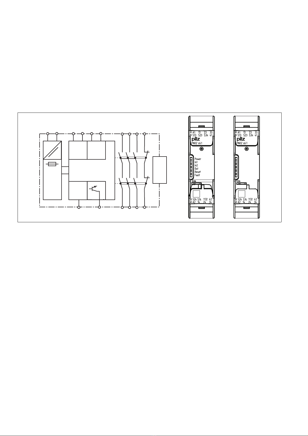
Características del dispositivo
`Salidas de relé de guía forzada:
– 3 contactos de seguridad (NA), sin retardo
– 1 contacto auxiliar (NC), sin retardo
`1 salida por semiconductor
`Posibilidades de conexión para:
– 2 elementos de mando (pulsadores)
`1 bloque de ampliación de contactos PNOZ-
sigma enchufable mediante conector
`Indicador LED para:
– tensión de alimentación
– estado de las entradas canal 1
– estado de las entradas canal 2
– estado de conmutación de los contactos
de seguridad
– circuito de realimentación
–Errores
`bornes de conexión enchufables (borne de
resorte o de tornillo)
Caratteristiche del dispositivo
`Uscite a relé a conduzione forzata:
– 3 contatti di sicurezza (NA) istantanei
– 1 contatto ausiliario (NC) istantaneo
`1 uscita a semiconduttore
`Possibilità di collegamento per:
– 2 elementi di comando (pulsanti)
`1 modulo di espansione contatti PNOZsigma
collegabile tramite connettore
`Indicatori LED per:
– Tensione di alimentazione
– Stato ingresso canale 1
– Stato ingresso canale 2
– Stato di commutazione contatti di sicurez-
za
– Circuito di retroazione
–Errore
`Morsetti di collegamento innestabili (a scelta
morsetti a vite o a molla)
Apparaatkenmerken
`Relaisuitgangen, mechanisch gedwongen:
– 3 veiligheidscontacten (M), niet-vertraagd
– 1 hulpcontact (V) niet-vertraagd
`1 halfgeleideruitgang
`Aansluitmogelijkheiden voor:
– 2 bedieningselementen (knoppen)
`1 contactuitbreidingsrelais PNOZsigma via
verbindingsstekkers aan te sluiten
`LED voor:
– Voedingsspanning
– Ingangstoestand kanaal 1
– Ingangstoestand kanaal 2
– Schakeltoestand veiligheidscontacten
– Terugkoppelcircuit
–Fout
`Steekbare aansluitklemmen (naar keuze
veerkracht- of schroefklemmen)

- 10 -
Características de seguridad
El dispositivo de mando a dos manos cumple
los requisitos de seguridad siguientes:
`El dispositivo de mando a dos manos impide
la habilitación de la instalación en los casos
siguientes:
– caída de la tensión
– fallo de un componente
– cortocircuito de un circuito de entrada
– defecto de bobina
– rotura de un conductor
– defecto a tierra
`en cada ciclo de conexión/desconexión,
comprobación de si los relés de salida del
dispositivo de seguridad abren y cierran cor-
rectamente
`El dispositivo lleva un fusible electrónico.
Caratteristiche di sicurezza
Il comando bimanuale risponde ai seguenti re-
quisiti di sicurezza:
`il comando bimanuale impedisce l'abilitazio-
ne dell'impianto nei seguenti casi:
– mancanza di tensione
– guasto di un componente
– cortocircuito di un circuito di ingresso
– guasti alla bobina
– rottura del cavo
–guastiaterra
`verifica ad ogni ciclo on-off della corretta
apertura e chiusura dei relé di uscita del mo-
dulo di sicurezza
`Il dispositivo è dotato di un fusibile elettroni-
co.
Veiligheidseigenschappen
Het tweehandenbedieningsrelais voldoet aan
de volgende veiligheidseisen:
`Het tweehandenbedieningsrelais verhindert
in de volgende gevallen dat de installatie vrij-
gegeven wordt:
– Uitvallen van de spanning
– Uitvallen van een component
– Kortsluiting van een ingangscircuit
– Defect in een spoel
– Kabelbreuk
– Aardsluiting
`Bij elke aan-uitcyclus wordt automatisch ge-
test of de uitgangsrelais van de veiligheids-
voorziening correct openen en sluiten
`Het apparaat heeft een elektronische zeke-
ring.
Diagrama de bloques/Asignación de
bornes Schema a blocchi/schema di collega-
mento dei morsetti Blokschema/klembezetting
*sólo para UB = 48 - 240 V AC/DC *solo per UB = 48 – 240 V AC/DC *alleen bij UB = 48 – 240 V AC/DC
Centro: Vista frontal con cubierta
Derecha: Vista frontal sin cubierta
Centro: vista frontale con copertura
Destra: vista frontale senza copertura
Midden: Vooraanzicht met afscherming
Rechts: Vooraanzicht zonder afscherming
Descripción de funciones
`El dispositivo de mando a dos manos ha de
activarse, en el plazo de 0,5 s segundos, ac-
cionando simultáneamente dos pulsadores.
Al soltar uno o los dos pulsadores, interrum-
pe la instrucción de control del movimiento
peligroso.
`Activar de nuevo: Los relés de salida se exci-
tan de nuevo sólo después de que hayan
sido soltados ambos elementos de manejo y
de que hayan sido accionados simultánea-
mente una vez más.
Descrizione del funzionamento
`Il comando bimanuale deve essere attivato
mediante l'azionamento simultaneo di due
pulsanti entro 0,5 s. Il comando del movi-
mento pericoloso viene interrotto al rilascio
di uno o di entrambi i pulsanti
`Per la riattivazione: i relé di uscita si attivano
nuovamente quando entrambi gli elementi di
comando vengono rilasciati e di nuovo azio-
nati simultaneamente.
Functiebeschrijving
`Het tweehandenbedieningsrelais wordt ge-
activeerd indien twee knoppen gelijktijdig,
binnen 0,5 s,bedient worden. Het onder-
breekt bij het loslaten van een of beide knop-
pen het besturingscommando voor de
gevaarlijke beweging.
`Opnieuw activeren: De uitgangsrelais komen
pas weer op, als beide bedieningselementen
losgelaten en opnieuw gelijktijdig bediend
worden.
InputInput
A1 A2 S2 S24
=
Power
Feed-
back
(Reset)
S 4
S1 S14
=
Y 2
(~)*
K1
K2
1 2
24 4
14
41
42
Interface
expansion
unit
( )*

- 11 -
Montaje
Montaje del dispositivo base sin bloque de
ampliación de contactos:
`Asegúrese de que la clavija de terminación
se ha enchufado en el lateral del dispositivo.
Conexión de dispositivo base y bloque de
ampliación de contactos PNOZsigma:
`Desenchufar la clavija de terminación del la-
teral del dispositivo y del bloque de amplia-
ción de contactos.
`Conectar el dispositivo base y el bloque de
ampliación de contactos mediante el conec-
tor suministrado antes de montar los
equipos en la guía normalizada.
Montaje en el armario de distribución
`Montar el dispositivo dentro de un armario
de distribución con un grado de protección
de IP54 como mínimo.
`Fijar el dispositivo a una guía normalizada
con ayuda del elemento de encaje de la parte
trasera.
`Asegurar el dispositivo en una guía normali-
zada vertical (35 mm) mediante un elemento
de sujeción (por ejemplo un soporte o un án-
gulo final).
`Deslizar el dispositivo hacia arriba o abajo
antes de separarlo de la guía.
Montaggio
Montaggio dispositivo base senza modulo di
espansione contatti:
`accertarsi che sia inserito il connettore termi-
nale sul lato del dispositivo.
Collegamento dispositivo base e modulo di
espansione contatti PNOZsigma:
`rimuovere il connettore terminale sul lato del
dispositivo base e sul modulo di espansione
contatti.
`Collegare il dispositivo base e il modulo di
espansione contatti con il connettore in do-
tazione prima di montare i dispositivi sulla
guida DIN.
Montaggio nell'armadio elettrico
`Il modulo di sicurezza deve essere montato
in un armadio elettrico con un tipo di prote-
zione corrispondente almeno al grado IP54.
`Fissare il dispositivo su una guida DIN con
l'aiuto dell'elemento a scatto situato sul re-
tro.
`In fase di montaggio, fissare il dispositivo su
una guida DIN verticale (35 mm) mediante
supporti (ad es. staffe di fissaggio o angoli
terminali).
`Prima di estrarlo dalla guida DIN, spingere il
dispositivo verso l'alto o verso il basso.
Montage
Basisrelais zonder contactuitbreidingsrelais
monteren:
`Zorg dat de afsluitconnector op de zijkant
van het apparaat is geplaatst.
Basisrelais en contactuitbreidingsrelais
PNOZsigma verbinden:
`Verwijder de afsluitstekker van de zijkant van
het basisrelais en het contactuitbreidingsre-
lais.
`Verbind het basisrelais en het contactuitbrei-
dingsrelais met de meegeleverde verbin-
dingsstekker voordat u de apparaten op de
DIN-rail monteert.
Montage in schakelkast
`Monteer het veiligheidsrelais in een schakel-
kast met een beschermingsgraad van mini-
maal IP54.
`Bevestig het apparaat met behulp van de re-
laisvoet op de achterzijde op een DIN-rail.
`Zet het apparaat op een verticale draagrail
(35 mm) vast met een eindsteun.
`Schuif voordat u de DIN-rail opheft het appa-
raat omhoog of omlaag.
Cableado
Tenga en cuenta:
`Respetar sin falta las especificaciones del
capítulo "Datos técnicos".
`Las salidas 13-14, 23-24, 33-34 son
contactos de seguridad, la salida 41-42 es
un contacto auxiliar (por ejemplo, para visua-
lización).
`Conectar un fusible (ver datos técnicos) an-
tes de los contactos de salida para evitar que
se suelden los contactos.
`Cálculo de la longitud de línea máxima Imáx.
en el circuito de entrada:
Rlmáx. = resistencia total máxima de la línea
(ver datos técnicos)
Rl/ km = resistencia de la línea/km
`Utilizar material de alambre de cobre con una
resistencia a la temperatura de 60/75 °C para
las líneas.
`Asegure un conexionado de protección
suficiente para cargas capacitivas e inducti-
vas en todos los contactos de salida.
Cablaggio
Prestare attenzione:
`attenersi assolutamente alle indicazioni ri-
portate al capitolo "Dati Tecnici".
`Le uscite 13-14, 23-24, 33-34 sono
contatti di sicurezza, l'uscita 41-42 è un con-
tatto ausiliario (ad es. per segnalazione).
`Per evitare la saldatura dei contatti, collegare
un fusibile (v. Dati Tecnici) a monte dei con-
tatti di uscita.
`Calcolo della lunghezza max. del conduttore
Imaxnel circuito di ingresso:
Rlmax = resistenza max. conduttore (v. Dati
Tecnici)
Rl/ km = resistenza del conduttore/km
`Per i cavi utilizzare fili di rame con una resi-
stenza termica di 60/75° C.
`Per i carichi capacitivi e induttivi occorre do-
tare tutti i contatti di uscita di un circuito pro-
tezione adeguato.
Bedrading
Let u op het volgende:
`Volg altijd de aanwijzingen in de paragraaf
"Technische gegevens".
`De uitgangen 13-14, 23-24, 33-34 zijn
veiligheidscontacten; de uitgang 41-42 is
een hulpcontact (b.v. voor signalering).
`Zeker de uitgangscontacten af (zie techni-
sche gegevens) om verkleving van de con-
tacten te voorkomen.
`Berekening van de max. kabellengte Imax in
het ingangscircuit:
Rlmax = max. weerstand totale kabel (zie
techn. gegevens)
Rl/ km = kabelweerstand/km
`Kabelmateriaal van koperdraad met een
temperatuurbestendigheid van 60/75 °C ge-
bruiken.
`Zorg bij capacitieve of inductieve belasting
van de uitgangscontacten voor adequate
contactbeschermingsmaatregelen.
Disposición para el funcionamiento Selezione del funzionamento Bedrijfsklaar maken
Conexión Collegamento Aansluiting
`Tensión de alimentación `Tensione di alimentazione `Voedingsspanning
tensión de alimentación/
tensione di alimentazione/
voedingsspanning
AC DC
`Circuito de entrada `Circuito d'ingresso `Ingangscircuit:
Circuito de entrada/ circuito di ingresso/in-
gangscircuit
monocanal/monocanale/eenkanalig bicanal/bicanale/tweekanalig
Pulsador de mando a dos manos
con detección de derivación/
Pulsante a due mani
con riconoscimento del cortocircuito/
Tweehandenbedieningsknop
met detectie van onderlinge sluiting
Rlmax
Rl / km
Imax =
Rlmax
Rl / km
Imax = Rlmax
Rl / km
Imax =
A1 L
A2 N
S14
A1 L+
A2 L-
S2
S1
S14
S24
S1
S2

- 12 -
`Circuito de realimentación `Circuito di retroazione `Terugkoppelcircuit
Circuito de realimentación/
circuito di retroazione/ terugkoppelcircuit/
Circuito de realimentación/ circuito di retroazione/terugkoppelcircuit
`Salida por semiconductor `Uscita a semiconduttore `Halfgeleideruitgang
Funcionamiento
El dispositivo está listo para el servicio cuando
el LED "POWER" permanece encendido.
Los LED indican el estado y los errores durante
el funcionamiento:
LED encendido
LED parpadea
INFORMACIÓN
Las indicaciones de estado y de error pue-
den producirse independientemente unas
de otras. Cuando se indica un error, se
enciende o parpadea el LED "Fault" (ex-
cepción: "Tensión de alimentación de-
masiado baja"). Un LED parpadeante
adicional señala una posible causa del er-
ror. Un LED adicional encendido perma-
nentemente señala condiciones de
funcionamiento normales. Puede ocurrir
que se produzcan varias indicaciones de
estado y de error al mismo tiempo.
Funzionamento
Il dispositivo è pronto all'uso quando il LED
Power resta sempre illuminato.
I LED indicano lo stato e gli eventuali guasti/er-
rori durante il funzionamento:
LED illuminato
LED lampeggiante
INFO
Gli indicatori di stato e di errore/guasto
possono accendersi indipendentemente gli
uni dagli altri. In caso di indicazione di erro-
re/guasto il LED "Fault" si illumina o lam-
peggia (eccezione: "tensione di
alimentazione troppo bassa"). Un ulteriore
LED lampeggiante rimanda ad una possibi-
le causa di guasto. Un ulteriore LED illumi-
nato staticamente rimanda ad uno stato
operativo normale. Possono accendersi più
indicatori di stato e di errore/guasto con-
temporaneamente.
Bedrijf
Het apparaat is bedrijfsklaar, als de LED "Po-
wer" permanent oplicht.
LED's geven de status en fouten tijdens het be-
drijf aan:
LED licht op
LED knippert
INFO
Status-LED's en fout-LED's kunnen onaf-
hankelijk van elkaar geactiveerd worden.
Bij een foutmelding licht de LED "Fault"
continu of knipperend op (uitzondering:
"Voedingsspanning te klein"). Een daar-
naast knipperende LED wijst op een moge-
lijke foutoorzaak. Een daarnaast continu
oplichtende LED wijst op een normale be-
drijfstoestand. Er kunnen meerdere status-
LED's en fout-LED's tegelijk geactiveerd
worden.
Indicadores de estado Indicazioni di stato Status-LED's
Alimentación
Hay tensión de alimentación.
Power
tensione di alimentazione presente.
Power
Voedingsspanning aanwezig.
In1
Pulsador de S11 accionado.
In1
Il pulsante su S11 è azionato.
In1
Knop op S11 is bediend.
In2
Pulsador de S21 accionado.
In2
Il pulsante su S21 è azionato.
In2
Knop op S21 is bediend.
Out
Los contactos de seguridad están cerrados
y la salida por semiconductor Y32 lleva
señal "High".
Out
i contatti di sicurezza sono chiusi e
sull'uscita a semiconduttore Y32 è presen-
te un segnale High.
Out
Veiligheidscontacten zijn gesloten en half-
geleideruitgang Y32 voert een hoog sig-
naal.
Reset
S34 recibe 24 V DC.
Reset
Su S34 sono applicati 24 V DC.
Reset
Op S34 staat 24 V DC.
Indicaciones de error Visualizzazioni di errore Foutweergaven
Todos los LED apagados
Diagnóstico: derivación/defecto a tierra;
dispositivo desconectado
`Solución: eliminar derivación/defecto a
tierra, desconectar durante 1 min. la ten-
sión de alimentación.
Tutti i LED spenti
Diagnosi: cortocircuito/guasto a terra; di-
spositivo spento
`Risoluzione: eliminare il cortocircuito/
guasto a terra, interrompere la tensione
di alimentazione per 1 min.
Alle LED's uit
Diagnose: Onderlinge sluiting/aardsluiting;
apparaat uitgeschakeld
`Oplossing: Onderlinge sluiting/aardslui-
ting herstellen, voedingsspanning gedu-
rende 1 min. uitschakelen.
Fault
Diagnóstico: clavija de terminación no
enchufada
`Solución: enchufar la clavija de termina-
ción, desconectar y conectar la tensión
de alimentación.
Fault
Diagnosi: connettore terminale non inserito
`Risoluzione: inserire il connettore termi-
nale, disinserire e reinserire la tensione di
alimentazione.
Fault
Diagnose: Afsluitconnector niet geplaatst
`Oplossing: Plaats afsluitconnector,
schakel voedingsspanning uit en weer in.
Fault
Diagnóstico: Error interno, dispositivo de-
fectuoso
`Solución: Desconectar y conectar la ten-
sión de alimentación, en su caso, cambi-
ar el equipo.
Fault
Diagnosi: errore interno, dispositivo guasto
`Risoluzione: disinserire e reinserire la
tensione di alimentazione, se necessario
sostituire il dispositivo.
Fault
Diagnose: Interne fout, apparaat defect
`Oplossing: Schakel voedingsspanning
uit en weer in; vervang eventueel het ap-
paraat.
Power
Diagnóstico: Tensión de alimentación de-
masiado baja
`Solución: Verificar tensión de alimenta-
ción.
Power
Diagnosi: tensione di alimentazione troppo
bassa
`Risoluzione: controllare la tensione di ali-
mentazione.
Power
Diagnose: Voedingsspanning te klein
`Oplossing: Voedingsspanning controle-
ren.
K5 K6
K5 L1
N
K6
S24
1 (2 , )
S 4
14 (24, 4)
S24
S 4
Y 2 PLC Input
S22 Gnd

- 13 -
In1, In2 alternativamente
Fault
Diagnóstico: error de conexión o deriva-
ción detectada entre S12 y S22 o error in-
terno
`Solución: corregir error de conexión o
derivación, desconectar y conectar la
tensión de alimentación.
In1, In2 alternativamente
Fault
Diagnosi: riconosciuto errore di collega-
mento o cortocircuito tra S12 e S22 o erro-
re interno
`Risoluzione: eliminare l'errore di collega-
mento o il cortocircuito, disinserire e
reinserire la tensione di alimentazione.
In1, In2 afwisselend
Fault
Diagnose: Aansluitfout of onderlinge slui-
ting tussen S12 en S22 gedetecteerd of in-
terne fout
`Oplossing: Verhelp aansluitfout of onder-
linge sluiting, schakel voedingsspanning
uit en weer in.
In1
Fault
Diagnóstico: simultaneidad rebasada:
canal 1 demasiado tarde o bloqueo de
conexión debido a interrupción momentá-
nea en S11; circuitos de entrada no accio-
nados simultáneamente
`Solución: abrir y cerrar simultáneamente
ambos circuitos de entrada S12 y S22.
In1
Fault
Diagnosi: superamento della simultaneità:
canale 1 in ritardo o bloccaggio all'accen-
sione dovuto a breve interruzione su S11;
circuiti d'ingresso non azionati simultanea-
mente
`Risoluzione: aprire e richiudere contem-
poraneamente entrambi i circuiti di in-
gresso S12 ed S22
In1
Fault
Diagnose: Gelijktijdigheidsoverschrijding:
Kanaal 1 te laat of inschakelblokkade we-
gens kortdurende onderbreking op S11; in-
gangscircuits niet gelijktijdig bediend
`Oplossing: Beide ingangscircuits, S12 en
S22 gelijktijdig openen en weer sluiten.
In2
Fault
Diagnóstico: simultaneidad rebasada:
canal 2 demasiado tarde o bloqueo de
conexión debido a interrupción momentá-
nea en S21; circuitos de entrada no accio-
nados simultáneamente
`Solución: abrir y cerrar simultáneamente
ambos circuitos de entrada S12 y S22.
In2
Fault
Diagnosi: superamento della simultaneità:
canale 2 in ritardo o bloccaggio all'accen-
sione dovuto a breve interruzione su S21;
circuiti d'ingresso non azionati simultanea-
mente
`Risoluzione: aprire e richiudere contem-
poraneamente entrambi i circuiti di in-
gresso S12 ed S22
In2
Fault
Diagnose: Gelijktijdigheidsoverschrijding:
Kanaal 2 te laat of inschakelblokkade we-
gens kortdurende onderbreking op S21; in-
gangscircuits niet gelijktijdig bediend
`Oplossing: Beide ingangscircuits, S12 en
S22 gelijktijdig openen en weer sluiten.
Errores - Fallos
`Funcionamiento defectuoso de los contac-
tos: En caso de contactos soldados,
después de abrir el circuito de entrada no es
posible ninguna nueva activación.
Errori - Guasti
`Funzionamento errato dei contatti: in caso di
saldatura dei contatti, dopo l'apertura dei cir-
cuiti di ingresso non è possibile nessuna
nuova attivazione.
Fouten - Storingen
`Contactfout: Bij verkleefde contacten is na
openen van het ingangscircuit geen nieuwe
activering mogelijk.
Datos técnicos Dati tecnici Technische gegevens
Datos eléctricos Dati elettrici Elektrische gegevens
tensión de alimentación Tensione di alimentazione Voedingsspanning
Tensión de alimentación UBDC Tensione di alimentazione UBDC Voedingsspanning UBDC 24 V
Tensión de alimentación UBAC/DC Tensione di alimentazione UBAC/
DC
Voedingsspanning UBAC/DC 48 - 240 V
Tolerancia de tensión Tolleranza di tensione Spanningstolerantie -15 %/+10 %
Consumo de energía con UBAC Potenza assorbita con UBAC Opgenomen vermogen bij UBAC 7,0 VA
Consumo de energía con UBDC Potenza assorbita con UBDC Opgenomen vermogen bij UBDC 3,5 W
Rango de frecuencia AC Campo di frequenza AC Frequentiebereik AC 50 - 60 Hz
Ondulación residual DC Ondulazione residua DC Rimpelspanning DC 20 %
Tensión y corriente en Tensione e corrente on Spanning en stroom op
Circuito de entrada DC: 24,0 V Circuito di ingresso DC: 24,0 V Ingangscircuit DC: 24,0 V
Contacto NA Apertura Maakcontact 20 mA
Circuito de realimentación DC:
24,0 VCircuito di retroazione DC: 24,0 V Terugkoppelcircuit DC: 24,0 V 15,0 mA
Número de contactos de salida Numero dei contatti di uscita Aantal uitgangscontacten
Contactos de seguridad (NA) sin
retardo:
Contatti di sicurezza (NA)
istantanei:
Veiligheidscontacten (M) niet-
vertraagd:
3
Contactos auxiliares (NC): Contatti ausiliari (NC): Hulpcontacten (V): 1
Categoría de los contactos de sali-
da según EN 954-1 Categoria dei contatti di uscita
secondo EN 954-1 Categorie uitgangscontacten
volgens EN 954-1
Contactos de seguridad (NA) sin re-
tardo:
Contatti di sicurezza (NA) istanta-
nei:
Veiligheidscontacten (M) niet-ver-
traagd:
1

- 14 -
Categoría de uso según
EN 60947-4-1 Categoria d'uso secondo
EN 60947-4-1 Gebruikscategorie volgens
EN 60947-4-1
Contactos de seguridad: AC1
con 240 V Contatti di sicurezza: AC1 con
240 VVeiligheidscontacten: AC1 bij 240 V Imin:0,01 A ,
Imax:U
B = 48 - 240 V AC/DC:
6,0 A, UB = 24 V DC: 8,0 A
Pmax: UB = 48 - 240 V AC/DC:
1500 VA, UB = 24 V DC: 2000 VA
Contactos de seguridad: DC1
con 24 V Contatti di sicurezza: DC1 con 24 V Veiligheidscontacten: DC1 bij 24 V Imin: 0,01 A , Imax: UB = 48 - 240
V AC/DC: 6,0 A,
UB = 24 V DC: 8,0 A
Pmax:
UB = 48 - 240 V AC/DC: 150 W,
UB = 24 V DC: 200 W
Contactos auxiliares: AC1 con
240 VContatti ausiliari: AC1 con 240 V Hulpcontacten: AC1 bij 240 V Imin: 0,01 A ,
Imax: UB = 48 - 240 V AC/DC:
6,0 A, UB = 24 V DC: 8,0 A
Pmax:
UB = 48 - 240 V AC/DC:
1500 VA, UB = 24 V DC: 2000 VA
Contactos auxiliares: DC1 con 24 V Contatti ausiliari: DC1 con 24 V Hulpcontacten: DC1 bij 24 V Imin: 0,01 A ,
Imax: UB = 48 - 240 V AC/DC:
6,0 A, UB = 24 V DC: 8,0 A
Pmax:
UB = 48 - 240 V AC/DC: 150 W,
UB = 24 V DC: 200 W
Categoría de uso según
EN 60947-5-1 Categoria d'uso secondo
EN 60947-5-1 Gebruikscategorie volgens
EN 60947-5-1
Contactos de seguridad: AC15
con 230 V Contatti di sicurezza: AC15 con
230 VVeiligheidscontacten: AC15 bij
230 V Imax:
UB = 48 - 240 V AC/DC: 3,0 A,
UB = 24 V DC: 6,0 A
Contactos de seguridad: DC13
con 24 V (6 ciclos/min.)
Contatti di sicurezza: DC13 con
24 V(6 cicli di commutazione/min)
Veiligheidscontacten: DC13 bij 24 V
(6 schakelingen/min)
Imax:
UB = 48 - 240 V AC/DC: 4,0 A,
UB = 24 V DC: 5,0 A
Contactos auxiliares: AC15 con
230 VContatti ausiliari: AC15 con 230 V Hulpcontacten: AC15 bij 230 V Imax:
UB = 48 - 240 V AC/DC: 3,0 A
UB = 24 V DC: 6,0 A
Contactos auxiliares: DC13 con
24 V(6 ciclos/min.)
Contatti ausiliari: DC13 con 24 V (6
cicli di commutazione/min)
Hulpcontacten: DC13 bij 24 V (6
schakelingen/min)
Imax:
UB = 48 - 240 V AC/DC: 4,0 A
UB = 24 V DC: 5,0 A
Material de los contactos Materiale di contatto Contactmateriaal AgCuNi + 0,2 µm Au
Protección externa de los contac-
tos (IK= 1 kA) según EN 60947-5-1 Fusibile dei contatti, esterno (IK= 1
kA) secondo EN 60947-5-1 Contactafzekering, extern (IK= 1
kA) volgens EN 60947-5-1
Fusible de acción rápida Fusibile rapido Smeltzekering snel
Contactos de seguridad: Contatti di sicurezza: Veiligheidscontacten: UB = 48 - 240 V AC/DC: 6 A,
UB = 24 V DC: 10 A
Contactos auxiliares: Contatti ausiliari: Hulpcontacten: UB = 48 - 240 V AC/DC: 6 A,
UB = 24 V DC: 10 A
Fusible de acción lenta Fusibile ritardato Smeltzekering traag
Contactos de seguridad: Contatti di sicurezza: Veiligheidscontacten: UB = 48 - 240 V AC/DC: 4 A
UB = 24 V DC: 6 A
Contactos auxiliares: Contatti ausiliari: Hulpcontacten: UB = 48 - 240 V AC/DC: 4 A
UB = 24 V DC: 6 A
Fusible automático 24 V AC/DC,
característica B/C
Interruttore automatico 24V AC/DC,
caratteristica B/C
Zekeringautomaat 24V AC/DC, ka-
rakteristiek B/C
Contactos de seguridad: Contatti di sicurezza: Veiligheidscontacten: UB = 48 - 240 V AC/DC: 4 A
UB = 24 V DC: 6 A
Contactos auxiliares: Contatti ausiliari: Hulpcontacten: UB = 48 - 240 V AC/DC: 4 A
UB = 24 V DC: 6 A
Salidas por semiconductor (a prue-
ba de cortocircuitos)
Uscite a semiconduttore (protette
da cortocircuiti)
Halfgeleideruitgangen (kortsluit-
vast)
24,0 V DC, 20 mA
Resistencia de línea total máx.
Rlmáx. por circuito de entrada
Max. resistenza totale del cavo Rl-
max per ogni circuito di ingresso
Max. weerstand totale kabel Rlmax
per ingangscircuit
30 Ohm
Datos característicos de técnica
de seguridad Dati tecnici di sicurezza Veiligheidstechnische kengege-
vens
Probabilidad de un fallo peligroso
por hora (PFHD)
Probabilità del verificarsi di un
evento pericoloso per ora (PFHD)
Waarschijnlijkheid van een gevaar-
lijk falen per uur (PFHD)
Contactos de seguridad sin retardo Contatti di sicurezza istantanei Veiligheidscontacten niet-vertraagd 2,44E-09 1/h
Límite de respuesta SIL (SIL CL) Livello SIL (SIL CL) SIL claim limit (SIL CL)
Contactos de seguridad sin retardo Contatti di sicurezza istantanei Veiligheidscontacten niet-vertraagd 3
Performance Level (PL) Performance Level (PL) Performance Level (PL)
Contactos de seguridad sin retardo Contatti di sicurezza istantanei Veiligheidscontacten niet-vertraagd e
Intervalo de las pruebas, en años Intervallo di verifica periodica in
anni
Prooftest-interval in jaren 20
Datos eléctricos Dati elettrici Elektrische gegevens

- 15 -
21 692-01
Tiempos Tempi Tijden
Retardo a la desconexión (tiempo
de respuesta según EN 574)
Ritardo allo sgancio (tempo di ri-
sposta secondo EN 574)
Afvalvertraging (reactietijd volgens
EN 574)
Contacto NA Apertura Maakcontact 40 ms
Contacto NC Chiusura Verbreekcontact 50 ms
Tiempo de recuperación Tempo di ripristino Resettijd 250 ms
Simultaneidad canal 1 y 2 Simultaneità canale 1 e 2 Gelijktijdigheid kanaal 1 en 2 0,5 s
A prueba de cortes de la tensión de
alimentación
Ininfluenza mancanza tensione di
alimentazione
Maximale onderbreking van de voe-
dingsspanning
20 ms
Datos relativos al medio ambien-
te Dati ambientali Omgevingscondities
CEM Compatibilità elettromagnetica EMC EN 60947-5-1, EN 61000-6-2,
EN 61000-6-4
Vibraciones según EN 60068-2-6 Oscillazioni secondo EN 60068-2-6 Trillingen volgens EN 60068-2-6
Frecuencia Frequenza Frequentie 10 - 55 Hz
Amplitud Ampiezza Amplitude 0,35 mm
Condiciones climáticas Sollecitazioni climatiche Klimaatcondities EN 60068-2-78
Distancias de fuga y dispersión su-
perficial
Caratteristiche dielettriche Lucht- en kruipwegen EN 60947-1
Tensión de aislamiento de dimen-
sionado
Tensione di isolamento nominale Nominale isolatiespanning 250 V
Resistencia tensión transitoria de
dimensionado
Tensione impulsiva nominale Nominale stoothoudspanning 4,0 kV
Temperatura ambiente Temperatura ambiente Omgevingstemperatuur -10 - 55 °C
Temperatura de almacenaje Temperatura di immagazzinamento Opslagtemperatuur -40 - 85 °C
Tipo de protección Grado di protezione Beschermingsgraad
Lugar de montaje (por ejemplo, ar-
mario de distribución)
Vano di montaggio (ad es. quadro
elettrico)
Inbouwruimte (b.v. schakelkast) IP54
Carcasa Custodia Behuizing IP40
Zona de bornes Zona morsetti Aansluitklemmen IP20
Datos mecánicos Dati meccanici Mechanische gegevens
Material de la carcasa Materiale custodia Behuizingsmateriaal
Carcasa Custodia Behuizing PC
Frontal Parte frontale Front PC
Sección máx. del conductor exter-
no con bornes de tornillo
Sezione max. dei cavi con morsetti
a vite
Max. doorsnede van de aansluitka-
bels bij schroefklemmen
1 conductor flexible 1 cavo flessibile 1 draad flexibel 0,25 - 2,50 mm² , 24 - 12 AWG
2 conductores de igual sección, fle-
xibles:
2 cavi di uguale sezione, flessibili: 2 draden met dezelfde doorsnede,
flexibel:
con terminal, sin revestimiento de
plástico
con capocorda, senza manicotto in
plastica
Met adereindhuls, zonder kunst-
stofhuls
0,25 - 1,00 mm² , 24 - 16 AWG
sin terminal o con terminal TWIN senza capocorda o con capocorda
TWIN
Zonder adereindhuls of met TWIN-
adereindhuls
0,20 - 1,50 mm² , 24 - 16 AWG
Par de apriete para bornes de tor-
nillo
Coppia di serraggio con morsetti a
vite
Aanhaalmoment bij schroefklem-
men
0,50 Nm
Sección máx. del conductor exter-
no con bornes de resorte: flexible
sin terminal
Sezione max. dei cavi con morsetti
a molla: flessibile senza capocorda
Max. doorsnede van de aansluitka-
bels bij veerklemmen/veerkracht-
klemmen: Flexibel zonder
adereindhuls
0,20 - 2,50 mm² , 24 - 12 AWG
Bornes de resorte: Número de bor-
nes por conexión
Morsetti a molla: slot morsetti per
collegamento
Veerklemmen/veerkrachtklemmen:
Klemmen per aansluiting
2
Longitud de desguarnecimiento Lunghezza isolamento Afstriplengte 9 mm
Medidas Dimensioni Afmetingen
Altura (bornes de tornillo) Altezza (morsetti a vite) Hoogte (schroefklemmen) 98,0 mm
Altura (bornes de resorte) Altezza (morsetti a molla) Hoogte (veerklemmen) 100,0 mm
Ancho Larghezza Breedte 22,5 mm
Profundidad Profondità Diepte 120,0 mm
Peso Peso Gewicht UB = 24 V DC: 190 g,
UB = 48 - 240 V AC/DC: 210 g
Son válidas las versiones actuales de las nor-
mas 2006-07.
Per le norme citate, sono applicate le versioni in
vigore al 2006-07.
Van toepassing zijn de 2006-07 actuele versies
van de normen.
Corriente térmica convencional Corrente termica convenzionale Conventionele thermische
stroom
Número de contactos Numero dei contatti Aantal contacten Ith (A) para UBAC/DC
111U
B = 48 - 240 V AC/DC: 6,00 A
UB = 24 V DC: 8,00 A
222U
B = 48 - 240 V AC/DC: 6,00 A
UB = 24 V DC: 8,00 A
333U
B = 48 - 240 V AC/DC: 4,50 A
UB = 24 V DC: 6,00 A

21 692-01, 2006-12Printed in Germany
Other manuals for PNOZ s6.1
1
Other Pilz Relay manuals

Pilz
Pilz 21165-3FR-06 User manual

Pilz
Pilz P2HZ 5 User manual

Pilz
Pilz PNOZ c2 User manual

Pilz
Pilz PNOZ c2 User manual

Pilz
Pilz PNOZ s4.1 User manual

Pilz
Pilz PNOZ X13 User manual

Pilz
Pilz PNOZ s22 Series User manual

Pilz
Pilz PNOZ 2VQ User manual

Pilz
Pilz PNOZ XV2.1P User manual

Pilz
Pilz PNOZ s30 User manual