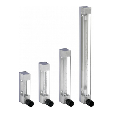
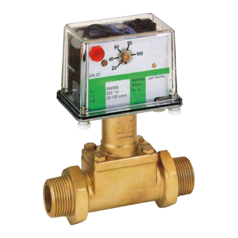
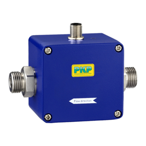
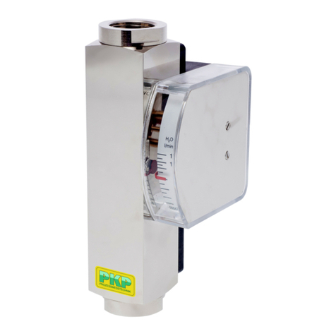
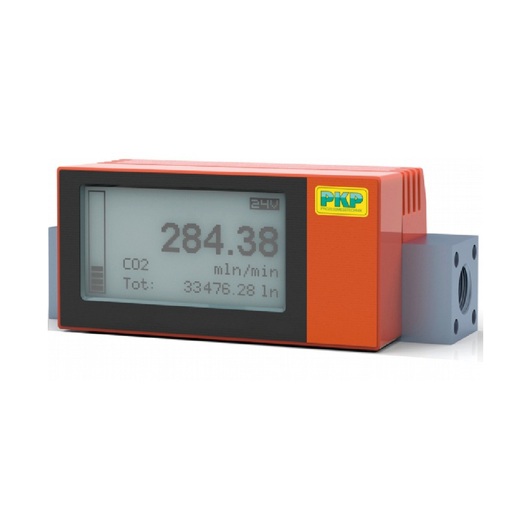
PKP DS20 User manual

Instruction Manual
DS20
Variable area flowmeter for low volumes,
compact construction
PKP Prozessmesstechnik GmbH
Borsigstraße 24
D-65205 Wiesbaden- ordenstadt
Tel.: ++49-(0)6122-7055-0
Fax: ++49-(0)6122-7055-50
Email: info@pkp.de

Table of Contents
Safety Information..................................................................................................................2
Installation and Commissioning.............................................................................................3
Wiring.....................................................................................................................................4
Limit switch (option K1 to K8)................................................................................................7
Service and Maintenance......................................................................................................7
Removing the measuring tube...............................................................................................8
Assembly of the measuring tube...........................................................................................8
Explosion drawings................................................................................................................9
Electronic transmitter (option)..............................................................................................11
Limit switch (option).............................................................................................................11
Controller (option)................................................................................................................12
Safety Information
General Instructions
To ensure safe operation, the device should only be operated according to the
specifications in the instruction manual. The requisite Health & Safety regulations for a
given application must also be observed. This statement also applies to the use of
accessories.
Every person who is commissioned with the initiation or operation of this device must have
read and understood the operating instructions and in particular the safety instructions!
The liability of the manufacturer expires in the event of damage due to improper use, non-
observance of this operating manual, use of insufficiently qualified personnel and
unauthorized modification of the device.
Proper sage
The devices of the DS20 series are used to monitor the continuous flow of liquids and
gases. Any other use is considered improper. Unless otherwise indicated, the scales of
the devices refer to water at 20 °C or air at 1.013 bar abs. and 0 °C. In particular,
applications in which shock loads occur (e.g. clocked operation) should be discussed and
checked beforehand with our technical personnel.
The devices of the DS20 series must not be used as the sole means of preventing
dangerous conditions on machines and systems.
Machines and systems must be designed in such a way that faulty conditions cannot lead
to a dangerous situation for the operating personnel.
Dangerous substances
For dangerous media such as e.g. Oxygen, Acetylene, flammable or toxic substances as
well as refrigeration systems, compressors, etc. must comply with the relevant regulations
beyond the general rules.
DS20 Instruction manual 02/2019 page 2

Qualified Personnel
Devices of the DS20 series may only be installed by suitably trained specialist personnel
who are able to install the devices properly. Qualified personnel are defined as those
persons who are familiar with the assembly, installation and commissioning of devices of
this type and who are appropriately qualified.
Inward Monitoring
Please check directly after delivery the device for any transport damages and deficiencies.
Additional with reference to the accompanying delivery note the number of parts must be
checked.
Claims for replacement or goods which relate to transport damage can only be considered
valid if the delivery company is notified without delay.
Installation and Commissioning
Mounting position
Vertical, flow direction up. Avoid vibrations in the pipe!
Installation instructions
•Before installing the DS20, make sure that there are no packaging residues in the
device.
•In devices without a valve and with the process connection "female thread", the
guide rod of the float moves from cone 44 into the area of the connection thread.
•When screwing in the connection, make sure that the guide rod is not bent.
•The inside diameter of the connection must be at least 8 mm for cones 44-51 and
at least 10 mm for cones 52 and 53.
•In order to avoid compression vibrations with gases, VDI/VDE 5313 Part 3 must be
observed. For devices without a valve, a restriction (valve) must be placed directly
upstream or downstream of the device (on the side where the larger volume is
located).
•In order to avoid mutual magnetic interference, the distance between the central
axes of the measuring tubes should be at least 120 mm and the distance to other
ferritic materials at least 60 mm when several devices are arranged in parallel.
•Foreign magnetic fields should be removed to such an extent that their field
strength at the flow meter is close to 0 mT.
DS20 Instruction manual 02/2019 page 3

Commissioning
Check the free movement of the float (5)* by observing the pointer which must follow the
change in flow. If this is not the case, the float and measuring tube (1;21) must be cleaned
(see removal of measuring tube). The free movement of the pointer is checked by
carefully moving it with the finger and observing the settling on the scale value.
In the event of a fault, it is recommended that the display unit be replaced (14).
When operating with solenoid valves, the flow must be limited to the maximum measured
value of the DS20 (also at the time of switching) in order to avoid damage to the float and
the stops. When starting up the system, slowly increase the flow rate to the desired value.
*Item numbers are shown in the exploded views.
Wiring
Please refer to the connection and wiring drawings in this chapter. Two Quickon
connectors are located on the rear of the DS20 for devices with electronic transmitters or
limit contacts. The lower one is labeled "S" in the wiring diagrams, the upper one is
labeled "T" in the wiring diagrams. Unused connections are sealed with a blind plug.
The following table shows the connections for each device configuration.
Type T
without
contacts
Type T
with MI
contact /
K1 o. K6
Type T
with MAX
contact /
K1 o. K7
Type T
with
MI /MAX
contact /
K3 o. K8
Type E
without
contact
without
impulse
Type E
with MI
contact /
K1 o. K6
Type E
with MAX
contact /
K2 o. K7
Type E
with pulse
output /
CP
Quickon
top „T“
----- ----- MAX
contact
MAX
contact
Current
output
Current
output
Current
output
Current
output
Quickon
below „S“
----- MI
contact
----- MI
contact
----- MI
contact
MAX
contact
Pulse
output
Measuring and display devices connected serially to the current output must not exceed a
load resistance of RL = (U-13.5 V) / 20 mA.
DS20 Instruction manual 02/2019 page 4

Installation
Fig. 3-1 - DS20 with electronic transmitter
Fig. 3-2 - DS20 with 2 limit switches in conjunction with isolating switch amplifier in Ex
version
DS20 Instruction manual 02/2019 page 5

Fig. 3-3 - Ex version of DS20 with electronic transmitter in conjunction with power supply
units and additional limit value contact or pulse output with isolating switch amplifier
DS20 Instruction manual 02/2019 page 6

Limit switch (option K1 to K8)
The optional limit switches are available as limit switches for the maximum value and/or
the minimum value. These are proximity switches according to E 60947-5-6 ( AMUR). A
maximum of two switches can be installed.
These switches have been designed for use in potentially explosive atmospheres.
However, the isolating switching amplifiers must be installed outside the hazardous area.
The limit switches are connected to the isolating switching amplifiers via the Quickon
connections on the rear of the devices (see "Installation instructions").
The MI -MI and MAX-MAX functions (see option K3) are integrated in the MI -MAX
switches of the DS20 at the factory. The MI -MI or MAX-MAX function is obtained by
setting the switching direction of the isolating switching amplifier accordingly.
The following table shows the assignment:
Function Switching direction of the isolating switching amplifier
canal 1 canal 2 canal 1 canal 2
MI MAX normal normal
MI MI normal reverse
MAX MAX reverse normal
Hint:
Switching direction "normal" means: Setting "inversion" on the isolating switching amplifier
to "OFF".
Switching direction "reverse" means: Setting "inversion" on the isolating switching amplifier
to "O ".
If the isolating switching amplifiers are used in safety-relevant applications, the switching
direction should be set to "normal" for all combinations (setting "inversion" on the isolating
switching amplifier to "OFF").
In order to ensure functional safety, the isolating switching amplifier must be used as a
protective device.
Service and Maintenance
The flow meters described here are maintenance free. They do not contain any
components that have to be repaired or replaced on site. Repairs are only carried out at
the manufacturer's works.
The devices must be installed and commissioned correctly. During operation, the devices
are maintenance-free, provided that parameters such as the type of medium, density,
temperature and pressure are adhered to. The material of the magnetic float switch must
be selected according to the medium.
Attention: Opening the pressure transmitter will void the warranty
DS20 Instruction manual 02/2019 page 7

Removing the measuring tube
The following steps are required to clean the measuring tube and the float:
•Removal from the pipeline
•Unscrew the upper hollow threaded bolt (6) (for cone 31-43) or remove the upper
circlip and the sleeve (for cone 44-51) or only the upper circlip (for cone 52-53).
•Removing upper float stop (3)
•Removal of the float - Caution: Float must not be bent!
•For the version with valve at the bottom, the screw plug at the bottom must first be
removed and all parts disassembled at the bottom.
•Cleaning of measuring tube and float
•To clean the valve, first loosen the lock nut (10) on the head. The spindle (12) with
the PTFE stuffing box seals and the pressure rings (9) can then be unscrewed.
Assembly of the measuring tube
The assembly is carried out in reverse order.
When installing the float, make sure that it is inserted correctly so that the medium flows
against the wide side of the measuring edge. The lower guide rod (below the measuring
edge) of the float is placed in the center bore of the lower stop. The guide rod must not be
bent.
DS20 Instruction manual 02/2019 page 8

Explosion drawings
With valve and controller
DS20 Instruction manual 02/2019 page 9

Without valve and controller
umber Part
1 Tube for unit with valve and controller
2 Socket
3 Float stop
4 Cone
5 Float
6 Threaded bold
7 Gasket
8 Screw sealing plug
9;10;11;12;13 Packing for valve
14 Indicator
15 ut M5
16;19 ozzle
17;20 Cutting ring fitting
18 Controller
21 Tube for unit without valve and controller
DS20 Instruction manual 02/2019 page 10

Electronic transmitter (option)
Power supply: 13,5...30 VDC
Power consumption: <= 21,5 mA
Load resistance Ri: (U-13,5 V) / 20 mA
Max. voltage: Umax = 30 V
Output signal: 4...20 mA
The output signal is not linear to the flow and must be linearized externally if necessary.
Electrical connection: Quick connection QUICKO
cable diameter: 4-6 mm
Max. wire cross-section: 0,34...0,75 mm²
Limit switch (option)
Type: Inductive switch
Ambient temperature: -25 °C to +100°C
ominal voltage: 8 VDC (Ri = 1 kOhm)
Output signal: <= 1 mA = 0; >= 3 mA = 1
Transistor relay for voltage supply of the limit switches
Type: Isolating switch amplifier acc. to
DI 19234 ( AMUR)
Power supply: 230 VAC, 115 VAC, 24 VDC
Relay output: 1 or 2 potential-free changeover contacts
Switching capacity: Max. 250 VAC, max. 4 A, max. 500 VA
Control circuit: Intrinsically safe [EEx ia] IIC
DS20 Instruction manual 02/2019 page 11

Controller (option)
Attention:
Differential pressure regulators are used to maintain a constant flow when the operating
pressure fluctuates. They are not pressure reducing valves.
The regulators DS20...1 and DS20...2 (upstream pressure regulators) are used for liquids
with variable upstream or downstream pressure and for gases with variable upstream
pressure and constant back pressure.
The regulators DS20...3 and DS20...4 (back pressure regulators) can only be used for
gases with fluctuating back pressure.
Max. flow rate for liquids: 100 l/h
Max. flow rates for gases: 3250 l/h
Max. pressure: 25 bar
Required differential pressure: > 400 mbar
Materials:
Housing Membranes prings
stainless steel PTFE stainless steel
brass Buna stainless steel
DS20 Instruction manual 02/2019 page 12

Flow Measurement and Monitoring
DS20
Variable Area Flowmeter
for Low Flow Volumes
Compact Construction
•for liquids and gases
•measuring range: 0 1...1 up to 25...250 l/h water
4...40 up to 800...8000 Nl/h
•measuring tube completely st. steel 1.4571
•max. pressure: 160 bar max. temperature: 200 °C
•scales for all operating conditions
designed as required
•local display min./max. contacts or
analogue output
•optional available with valve
• Ex-Version acc. to ATEX
Description:
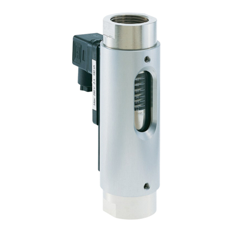
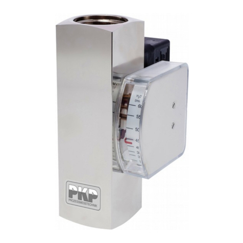
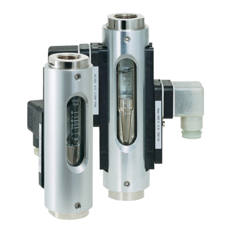
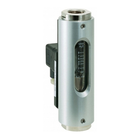
The model series DS20 flow meters work according to the
suspended float principle of measurement. The device has a
cone- shaped float that moves within a cylindrical measuring
tube. The flowing gas or liquid moves the float in the direction
of the flow. The movement of the float is transmitted magnet-
ically to a dial indicator mounted outside on the measuring
tube. The indicator is fitted with a scale appropriate for the
operating range encountered. f necessary, the indicator can
also be fitted with contacts or an analogue output.
Typical applications:
Model series DS20 flow meters are intended to measure and
monitor gases or low- viscosity liquids, such as those found in
applications like cooling systems for welding machines, laser
and tube systems, pump monitoring, compressors, etc. Since
all parts coming in contact with the medium being monitored
are made of high- quality st. steel 1.4571, this device is also
suitable for use with caustic/ corrosive media.
PKP Prozessmesstechnik GmbH
Borsigstr. 24 • D-65205 Wiesbaden
S +49 (0) 6122-7055-0 • +49 (0) 6122 7055-50
[email protected] • www.pkp.de
PKP Process Instruments Inc.
10 Brent Drive • Hudson, MA 01749
S +1-978-212-0006 • +1-978-568-0060
[email protected] • www.pkp-usa.com
190211

Models:
• Flowmeter with local dial indicator display
• Dial indicator display, 1 M N contact
• Dial indicator display, 1 MAX contact
• Dial indicator display, 1 M N contact, 1 MAX contact
• Dial indicator display, analogue output: 4 to 20 mA
Process Connection:
Version without needle al e (connection at top/ bottom):
all threaded connections as per model code, PN 100 (standard) or
PN 160, all flange connections
Version with needle al e (connection at back):
all threaded connections as per model code, PN 40 (standard) or
PN 100, flange connections not possible
Measuring Ranges:
Code
(water)
Measuring range
water
20 °C [l/h]
Code
(air)
Meas. range air,
0 °C, 1,013 bar
abs. [Nl/h]
Prssure
loss
[mbar]
W1 0,1...1 L1 4...40 6
W2 0,16...1,6 L2 6...60 6
W3 0,25...2,5 L3 10...90 6
W4 0,4...4 L4 14...140 6
W5 0,6...6 L5 20...200 6
W6 1...10 L6 32,5...325 8
W7 1,6...16 L7 50...500 8
W8 2,5...25 L8 80...800 8
W9 4...40 L9 140...1400 11
W10 6...60 L10 200...2000 11
W11 10...100 L11 325...3250 11
W12 16...160 L12 500...5000 13
W13 25...250 L13 800...8000 13
The indicated measuring ranges -especially for air- serve for orientation.
Please specify the following process conditions when making enquiries:
Medium, pressure and temperature
We create an individual scale for you at no extra charge.
Dimensions:
Technical Data:
Materials: wetted parts made of st. steel 1.4571
housing made of 1.4301
Max. pressure: PN 100 (standard), PN 10, 40, 160
acc. to order code
Max. media-temperature:
local display: − 80 °C…+200 °C (+150 °C with valve)
with contacts: − 40 °C…+150 °C
with analogue output.: − 40 °C…+150 °C
Protection class: P65
Accuracy: ± 4 % of measured range value
Order Code:
Order number: DS20.
Float Type Flowmeter
41G4. 6. 0. 1. 0
Process connection:
41G4 = G 1/4 G, PN 40
41G6 = G 1/4 G, PN 100 (Standard)
4266 = G 3/8 G, PN 100 (at meas. ranges 12 + 13)
41G7 = G 1/4 G, PN 160
41T4 = 1/4" NPT G, PN 40
41T6 = 1/4" NPT G, PN 100
41T7 = 1/4" NPT G, PN 160
53C4 = compression fitting 6 mm, PN 40
53C6 = compression fitting 6 mm, PN 100
53C7 = compression fitting 6 mm, PN 160
53P1 = hose connection 6 mm, PN 10
54C4 = compression fitting 8 mm, PN 40
54C6 = compression fitting 8 mm, PN 100
54C7 = compression fitting 8 mm, PN 160
54P1 = hose connection 8 mm, PN 10
55C4 = compression fitting 10 mm, PN 40
55C6 = compression fitting 10 mm, PN 100
55C7 = compression fitting 10 mm, PN 160
56C4 = compression fitting 12 mm, PN 40
56C6 = compression fitting 12 mm, PN 100
56C7 = compression fitting 12 mm, PN 160
01D4 = flanges DN 15, PN 40
02D4 = flanges DN 25, PN 40
01A1 = flanges ANS 1/2", 150 lbs RF
02A1 = flanges ANS 1", 150 lbs RF
01A2 = flanges ANS 1/2", 300 lbs RF
02A2 = flanges ANS 1", 300 lbs RF
Measuring range:
1…13 = acc. to table
99 = special measuring range
Val e:
0 = without
1 = valve on input side, valve seat made of silver
2 = valve on input side, valve seat made of PCTFE
3 = valve on output side, valve seat made of silver
4 = valve on output side, valve seat made of PCTFE
Display:
1 = local pointer display
2 = local pointer display, 1 M N-contact
3 = local pointer display, 1 MAX-contact
4 = local pointer display, 1 M N-, 1 MAX-contact
5 = local pointer display, analogue output 4…20 mA
6 = local pointer display, analogue output 4…20 mA,
1 M N-contact
7 = local pointer display, analogue output 4…20 mA,
1 MAX-contact
Options:
0 = without
9 = please specify in plain text
Contacts:
Type: nductive (NAMUR acc. to EN 50227)
Nominal oltage: 8 VDC
Recommended for operating the contacts: Switch amplifier
P+F (see Data sheet P+F)
Analogue Output:
Power supply: 24 VDC
Output: 4…20 mA, 2-wire
Load impedance: (U–13,5 V) / 20 mA
Electr. connection: QU KON quick connection
PKP Prozessmesstechnik GmbH
Borsigstr. 24 • D-65205 Wiesbaden
S +49 (0) 6122-7055-0 • +49 (0) 6122 7055-50
[email protected] • www.pkp.de
PKP Process Instruments Inc.
10 Brent Drive • Hudson, MA 01749
S +1-978-212-0006 • +1-978-568-0060
[email protected] • www.pkp-usa.com
Table of contents
Other PKP Measuring Instrument manuals
Popular Measuring Instrument manuals by other brands

PCB Piezotronics
PCB Piezotronics 3711E11200G Installation and operating manual

Laserworld
Laserworld RGB-2.8 manual

Huvitz
Huvitz CLM-3100P Service manual

Siemens
Siemens SITRANS F US SONOFLO SONOKIT manual

Besantek
Besantek BST-HVD18 instruction manual

Agilent Technologies
Agilent Technologies N9320A user guide

Transforming Technologies
Transforming Technologies Ohm Metrics SRM330 instruction manual

Greystone Energy Systems
Greystone Energy Systems CR3 Series installation instructions

Raytech
Raytech TR-MARK III instruction manual

PCE Instruments
PCE Instruments PCE-RCM 16 user manual

Lisun Group
Lisun Group XYL-VI brochure

MFJ
MFJ MFJ-802B instruction manual