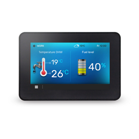
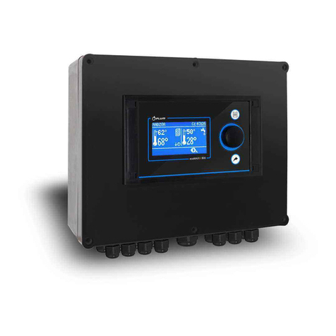
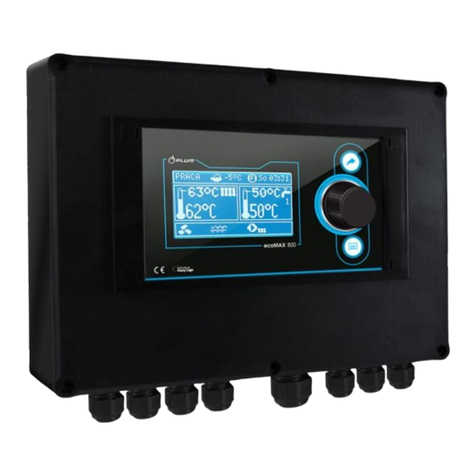
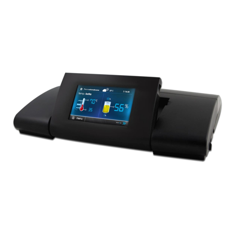
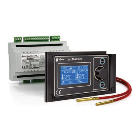
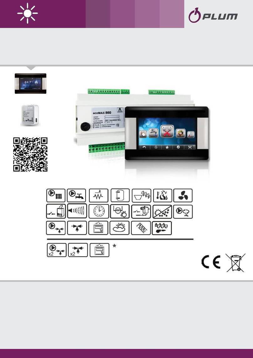
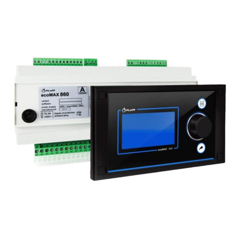
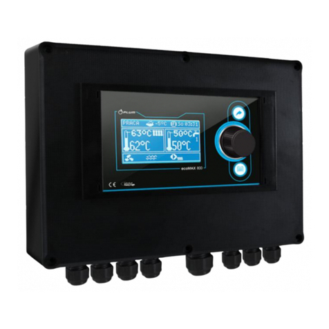
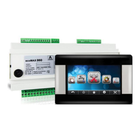
Plum ecoMAX920P1-K User manual

REGULATOR
ecoMAX920P1-K
FOR AUTOMATIC SOLID FUEL FIRED BOILERS
INSTALLATION AND OPERATING MANUAL
ISSUE: 1.3_EN
06-2019
functions available in the additional
module B
* the ecoSTER TOUCH or ecoSTER200 room panel, eSTER_x80 wireless room panel or eSTER_x40
wireless thermostat and ecoNET300 Internet module isn’t the standard equipment of the
regulator.
ecoNET300*
ecoNET.apk
www.econet24.com
ecoSTER200*
ecoSTER TOUCH*
eSTER_x80*
eSTER_x40*

ELECTRIC DEVICE UNDER VOLTAGE!
Before any action related to the power supply (cables connection,
device installation etc.) check if the regulator is not connected to the
mains!
Installation should be done by a person with appropriate electrical
qualifications. Improper cables connection could result in the regulator
damage.
The regulator cannot be used in steam condensation conditions and
cannot be exposed to water.

3
TABLE OF CONTENTS
1RECOMMENDATIONS REGARDING SAFETY ........ 4
2GENERAL INFORMATION .................................... 5
3INFORMATION ABOUT DOCUMENTATION......... 5
4STORAGE OF DOCUMENTATION......................... 5
5APPLIED SYMBOLS .............................................. 5
6DIRECTIVE WEEE 2012/19/UE............................. 5
USER SETTINGS ............................................ 7
7USER MENU - STRUCTURE .................................. 8
8THE REGULATOR SUPPORT................................. 9
8.1 BUTTONS DESCRIPTION......................................... 9
8.2 DESCRIPTION OF THE MAIN WINDOW....................... 9
8.3 SWITCHING ON AND OFF THE BOILER..................... 10
8.4 PRESET TEMPERATURE SETTING ............................ 10
8.5 FIRIE UP MODE ................................................ 10
8.6 OPERATION MODE .......................................... 10
8.7 REGULATION MODES .......................................... 11
8.8 SUPERVISION MODE ....................................... 11
8.9 BURNING OFF MODE....................................... 12
8.10 STOP MODE..................................................... 12
8.11 GRATE MODE .................................................. 12
8.12 BURNER CLEANING............................................. 12
8.13 HUW SETTINGS................................................. 13
8.14 HUW PRESET TEMPERATURE SETTINGS .................. 13
8.15 HYSTERESIS OF HUW......................................... 13
8.16 ENABLING THE SUMMER FUNCTION ....................... 13
8.17 HUW CONTAINER DISINFECTION........................... 13
8.18 MIXER CIRCLE SETTINGS ...................................... 13
8.19 WEATHER CONTROL ........................................... 14
8.20 NIGHT DECREASE SETTINGS DESCRIPTION ................ 15
8.21 WORKING ACCORDING TO SCHEDULE ..................... 15
8.22 CONTROL OF THE CIRCULATION PUMP .................... 16
8.23 FUEL LEVEL CONFIGURATION ................................ 16
8.24 FEEDER EFFICIENCY TEST...................................... 16
8.25 INFORMATION................................................... 17
8.26 MANUAL CONTROL ............................................ 17
8.27 ROOM THERMOSTAT AND PANEL........................... 17
8.28 COOPERATION WITH THE INTERNET MODULE........... 17
INSTALLATION AND SERVICE SETTINGS....... 19
9HYDRAULIC SCHEMES ....................................... 20
10 TECHNICAL DATA .............................................. 23
11 CONDITIONS OF STORAGE AND TRANSPORT ... 23
12 REGULATOR INSTALLATION .............................. 23
12.1 ENVIRONMENTAL CONDITIONS ............................. 23
12.2 INSTALLATION REQUIREMENTS.............................. 23
12.3 INSTALLATION OF CONTROL PANEL......................... 23
12.4 MOUNTING OF MODULE...................................... 24
12.5 IP PROTECTION RATE .......................................... 25
12.6 ELECTRIC CONNECTION........................................ 25
12.7 ELECTRIC SCHEME .............................................. 27
12.8 CONNECTION OF TEMPERATURE SENSORS ............... 29
12.9 CONNECTING THE WEATHER TEMP.SENSOR ............ 29
12.10 CONNECTING THE EXHAUST TEMPERATURE SENSOR...29
12.11 TEMPERATURE SENSORS CHECKING ........................30
12.12 OPTICAL SENSOR CONNECTION..............................30
12.13 MIXERS ROOM TEMPERATURE CONNECTION ............30
12.14 BOILER ROOM THERMOSTAT CONNECTION...............30
12.15 RESERVE BOILER CONNECTION...............................31
12.16 CONNECTION OF ALARM SIGNALLING......................31
12.17 MIXER CONNECTION ...........................................32
12.18 CONNECTING TEMPERATURE LIMITER .....................33
12.19 CONNECTING OF ROOM PANEL..............................33
12.20 CONNECTING OF WIRELESS ROOM PANEL.................33
13 SERVICE MENU - STRUCTURE............................34
14 DESCRIPTION OF SERVICE SETTINGS .................36
14.1 BURNER ...........................................................36
14.2 BOILER .............................................................37
14.3 CH AND HUW ..................................................38
14.4 BUFFER ............................................................39
14.5 MIXER..............................................................39
14.6 OTHER PARAMETERS ...........................................40
15 ALARMS DESCRIPTIONS.....................................41
15.1 BOILER MAX.TEMPERATURE EXCEEDING .................41
15.2 OVERHEATING OF THE BURNER..............................41
15.3 BOILER TEMPERATURE SENSOR DAMAGE .................41
15.4 FEEDER TEMPERATURE SENSOR DAMAGE.................41
15.1 FEEDER CONTROL SYSTEM FAILURE.........................41
15.2 OVERHEATING BOILER,STB OPEN CONTACT ............41
15.3 UNSUCCESSFUL BOILER FIRING-UP ATTEMPT ............42
15.4 NO COMMUNICATION .........................................42
15.5 OPEN BOILER DOOR ............................................42
15.6 UNSUCCESSFUL ATTEMPT TO LOAD THE TANK...........42
16 OTHER FUNCTIONS............................................42
16.1 POWER STOPPAGE..............................................42
16.2 ANTIFREEZING PROTECTION..................................42
16.3 PUMP PROTECTION FUNCTION AGAINST STAGNATION 42
16.4 NETWORK FUSE REPLACEMENT..............................42
16.5 REPLACEMENT OF CONTROL PANEL ........................42
17 LAMBDA SENSOR MODULE ...............................42
18 THE REGULATOR CONFIGURATION BY BOILER
PRODUCER.....................................................................43
19 POSSIBLE FAULTS DESCRIPTION ........................44

4
1Recommendations regarding safety
Requirements concerning safety are
described in detail in individual chapters of
this manual. Apart from them, the following
requirements should in particular be
observed.
Before starting assembly, repairs or
maintenance, as well as during any
connection works, please make sure
that the mains power supply is
disconnected and that terminals and
electric wires are devoid of voltage.
After the regulator is turned off,
dangerous voltage still can occur on
its terminals.
The regulator cannot be used at
variance with its purpose.
Additional automatics which protect
the boiler, central heating system,
and domestic hot water system
against results of malfunction of the
regulator, or of errors in its software,
should be applied.
Choose the value of the programmed
parameters accordingly to the given
type of boiler and fuel, taking into
consideration all the operational
conditions of the system. Incorrect
selection of the parameters can cause
malfunction of the boiler (e.g.
overheating of the boiler, the flame
going back to the fuel feeder, etc.),
The regulator is intended for boiler
manufacturers. Before applying the
regulator, a boiler manufacturer
should check if the regulator’s mating
with the given boiler type is proper,
and whether it can cause danger.
The regulator is not an intrinsically
safe device, which means that in the
case of malfunction it can be the
source of a spark or high temperature,
which in the presence of flammable
dusts or liquids can cause fire or
explosion. Thus, the regulator should
be separated from flammable dusts
and gases, e.g. by means of an
appropriate body.
The regulator must be installed by a
boiler manufacturer in accordance
with the applicable safety standards.
The programmed parameters should
only be altered by a person
familiarized with this manual.
The device should only be used in
heating systems in accordance with
the applicable regulations.
The electric system in which the
regulator operates must be protected
by means of a fuse, selected
appropriately to the applied loads.
The regulator cannot be used if its
casing is damaged.
In no circumstances can the design of
the regulator be modified.
Electronic isolation of the connected
devices is applied in this regulator.
The regulator is equipped with internal
overcurrent protection, one-polar,
which have an impact on the safety of
use. The condition of its correct
operation is the proper connection of
the power cable to the electrical
network. It is absolutely necessary to
ensure that the L phase wire is not
changed with the N neutral wire.
Ensure that the polarity of the L and N
wires is correct by measuring at their
terminals.
Prevent access to the regulator of
people who do not know the content of
this manual, especially children.

5
2General information
The regulator ecoMAX920P1-K is a device
designed to control the operation of a boiler
with automatic feeding of solid fuel with a
igniter. Flame detection is performed with
the use of an optical flame brightness sensor.
It can control the work of central heating and
hot water circuits and also control the work
of 5 mixing heating circuits. The required
temperature of heating circuits can be set on
the basis of data obtained from the main
sensor. The possibility of cooperation with
room thermostats, separate for each heating
circuit is beneficial for maintaining
comfortable temperature in heating rooms.
Moreover, the device turns on the spare
boiler (-gas or –oil). The regulator may
operate in connection with additional wire
room thermostat/panel ecoSTER200,
ecoSTER TOUCH and wireless room
thermostat/panel eSTER_x80 or eSTER_x40
installed in rooms and ecoNET300 Internet
module. Additionally it cooperates with
ecoLAMBDA module and extension B and C
modules.
The regulator may be used in households
and other similar premises and in light
industry facilities.
3Information about documentation
The regulator manual is a supplement for the
boiler manual. In particular, except for this
manual, the boiler manual should also be
observed. The regulator manual is divided
into two parts: for user and fitter. Yet, both
parts contain important information,
significant for safety issues, hence the user
should read both parts of the manual.
We are not responsible for any damages
caused by failure to observe these
instructions.
4Storage of documentation
This assembly and operation manual, as well
as any other applicable documentation,
should be stored diligently, so that it was
available at any time. In the case of removal
or sale of the device, the attached
documentation should be handed over to the
new user / owner.
5Applied symbols
In this manual the following graphic symbols
are used:
- useful information and tips,
- important information, failure to
observe these can cause damage of
property, threat for human and
household animal health and life.
Caution: the symbols indicate important
information, in order to make the manual
more lucid. Yet, this does not exempt the
user from the obligation to comply with
requirements which are not marked with a
graphic symbol!
6Directive WEEE 2012/19/UE
Purchased product is designed and made of
materials of highest quality.
The product meets the requirements of the
Directive 2012/19/EU of 4 July 2012 on
waste electrical and electronic
equipment (WEEE), according to which it is
marked by the symbol of crossed-out
wheeled bin (like below), meaning that
product is subjected to separate collection.
Responsibilities after finishing a period of
using product:
dispose of the packaging and product at
the end of their period of use in an
appropriate recycling facility,
do not dispose of the product with other
unsorted waste,
do not burn the product.
By adhering obligations of waste electrical
and electronic equipment controlled disposal
mentioned above, you avoid harmful.

6

USER SETTINGS
ecoMAX920P1-K

8
7User menu - structure
Boiler settings
Preset boiler temp.
Weather contr.boiler*
Heating curve*
Curve shift*
Room temp.factor*
Output modulation
MAX boiler output
MAX blow-in output
MAX exhaust fan
MAX oxygen*
Average hysteresis H2
Aver. boiler output
Average blow-in output
Average exhaust fan
Average oxygen*
MIN hysteresis H1
MIN boiler output
MIN blow-in output
MIN exhaust fan
MIN oxygen*
Boiler hysteresis
Min. boiler output FL*
Max. boiler output FL*
Blow-in output-grate*
Exh. fan –grate*
Feeder efficiency
Feeder:
Feeder test
Fuel dose from test
Efficiency test time
Feeder filling
Boiler oper. mode*
Pellet, Grate
Regulation mode
Standard, Fuzzy Logic
Lambda Fuzzy Logic*
Fuel type
Fuel level
Alarm level
Fuel level calibration
Burner cleaning
Lambda sensor calibr. *
Cleaning intensity
Exch. clean start
Exch. clean stop
HUW settings*
Preset HUW temp.
HUW pump mode
Off, Priority, No priority
HUW cont. hysteresis
HUW disinfection
Night time decrease
Boiler
Off
Reduction value
Schedule
Mixer 1-5
HUW container
Circulation pump*
Sommer/Winter
SUMMER mode
Summer, Winter, Auto*
Activ. temperature SUMMER
Deactv. temperature SUMMER
Mixer settings 1-5*5
Preset mixer temp.
Mixer room thermostat
Weather control mixer*
Heating curve mixer*
Curve shift*
Room temp. factor*
General settings
Clock
Date
Screen brightness
Screen contrast
Sound
Language
WiFi*
Weather sensor
Sensor correction
Radio module settings*
Pairing mode
Delete paired devices
* not available if proper sensor or
additional module not connected or the
parameter is hidden.
Main menu
Information
Boiler settings
HUW settings*
Mixer 1-5 settings*
Night time decrease
Summer/Winter
Work schedule
Off, Schedule
General settings
Manual control
Alarms
Service settings

9
8The regulator support
8.1 Buttons description
1. MENU entry buton,
2. ,,TOUCH and PLAY” knob,
3. EXIT buton.
The „TOUCH and PLAY” knob turning cause
increase or decrease of edited parameter. It
is a part of fast handling of the controller.
Pressing the knob causes enter edition mode
of chosen parameter or selecting its volume.
Pressing EXIT button causes exit selected
menu level and also exit selected volume of
a parameter.
8.2 Description of the main window
Legend:
1. Regulator operating modes: FIRE UP,
OPERATION, SUPERVISION, BURNING
OFF, CLEANING, STOP,
2. boiler preset temperature,
3. boiler measured temperature,
4. functions having influence on preset
boiler temperature:
- preset boiler temperature
decrease due to thermostat
disconnection,
- preset boiler temperature
decrease due to activated time
spans,
- boiler preset temperature during
loading HUW,
- boiler preset temperature increase
from mixer circulation,
- activation of weather control for
the boiler circuit,
- active return protection,
- raising the preset temperature in
order to load the buffer.
5. signalling fan operation,
6. signalling fuel feeder operation,
7. signalling CH pump operation,
8. signalling HUW pump operation,
9. HUW measured temperature,
10. preset HUW temperature,
11. clock and weekday,
12. part of the screen coshared between two
icons:
–symbolizes operating heater, and
the digit next to it stands for a number of
Firing-up attempts,
–symbolizes activating automatics
of furnace cleaning,
13. outside (weather) temperature,
14. current boiler power level,
15. signalling activating Fuzzy Logic mode,
16. signalling HUW disinfection,
17. signalling burner feeder operation,
18. symbol of active, rotary cleaning of the
burner.
Right window on the main screen is
configurable, allows on changing information
displayed there. It is possible to choose a
configuration displaying by twisting the
“TOUCH and PLAY” knob.
Right window on the main screen may also
display the fuel level view, providing that this
parameter is set correctly.
8
13
14
15
11
10
9
16
18
12
7
6
5
2
4
1
3
FIRE UP
Mon
17
2
3
1

10
Tip: Fuel level may be displayed on
ecoSTER200, ecoSTER TOUCH and
eSTER_x80, eSTER_x40 room thermostat /
panel.
8.3 Switching On and Off the boiler
After connecting the power the controller
shows the settings put before connecting the
electricity. If the controller has not operated
before it will start up in Stand-by mode. In
this mode the screen is dimmed, actual time
and information “Boiler Off”is displayed.
In Stand-by mode protecting pumps against
going stale function is in operation. It is
executed by temporary switching them on.
Therefore it is advised to keep the electrical
power to the controller on when the boiler is
not in use. It is possible to start up the boiler
by pressing the “TOUCH and PLAY” knob and
selecting „Active regulator?”or setting
parameters of its operation (MENU button)
without connecting it to the electrical power.
After making sure that fuel is in the silo, and
the hatch is closed the boiler can be switched
on. After switching on the boiler goes into
Firing-up phase.
8.4 Preset temperature setting
The boiler preset temperature and HUW
preset temperature, and mixer circuits preset
temperature can be set in the menu
(possible temperatures are restricted with
range of respective service parameters):
Boiler settings →Preset boiler temp.
HUW settings →Preset HUW temp.
Mixer settings 1-5 →Preset mixer temp.
The parameter value Preset boiler temp., is
by regulator bypassed when the preset boiler
temperature is controlled by weather sensor.
Regardless of that, the preset boiler temp. is
automatically increased to load the hot user
water tank and power heating circuits of
mixers.
8.5 FIRIE UP mode
The FIRE UP mode is for automatic firing up
of furnace in boiler. Total time of firing up
proces is dependand on controller’s settings
and on boiler’s condition before firing up.
Parameters influencing firing up process are
in the menu:
Service settings →
Burner settings →Firing-up
In case of failed attempt of firing up the
furnace another attempts are taken during
which amount of fuel is reduced to 10% of
first attempt’s dose.
After three failed firing up attempts an alarm
“Unsuccessful boiler firing-up attempt”is
reported. Boiler’s operation is then stopped.
It is not possible to automatically continue
boiler’s operation. Service intervention is
required. After finding and solving the cause
of firing up failure the boiler should be fired
up again.
8.6 OPERATION mode
In the OPERATION modes the burner fan
operates constantly. Fuel feeder is engaged
periodically. Period consists of feeder
operating time and pause in fuel feeding
time.
The Cycle time OPERAT parameter is located
in the menu:
Service settings →Burner settings →
Operation
Feeder operation time is calculated
automatically depending on the required
current power of the burner, Feed efficiency
and Calorific value of the fuel. Parameters of
blow-in and exhaust output for different
power levels of the burner are available in
the menu:
Boiler Off
Feed time
operat
Feed interval
operat
Feed time
operat
Feed interval
operat

11
Boiler settings →Output modulation
8.7 Regulation modes
Can choose between two adjustment modes
responsible for stabilizing the boiler preset
temperature Standard and Fuzzy Logic. This
mode changes in the menu:
Boiler settings →Regulation mode
Standard mode operation
If the boiler’s temperature reach preset one
then the controller switches off to the
SUPERVISION mode.
The regulator is equipped with boiler’s power
modulation mechanism which allows for
gradual power reduction when approaching
the preset temperature. There are three
power boiler levels: MAX, Average, MIN.
Current power level is displayed on the
screen as 3 segmented indicato rat the left
side of boiler’s icon.
Each level can be allocated with seperate
blow-in output and exhaust output which
influence on actual boiler’s power level.
Power levels parameters are available in the
menu:
Boiler settings →Output modulation
The controller regulates burner’s power with
which it operates depending on preset
temperature and defined hysteresis Average
hysteresis H2 and MIN hysteresis H1. It is
possible to configure volumes hysteresis H1
and H2 in such a way that modulation is
done without intermediate position. That
means switching from MAX to MIN with
omission of Average power.
Operation in Fuzzy Logic mode
In Fuzzy Logic mode the controller
automatically regulates burner power to
allow boiler operation in such a way to
maintain its temperature on preset level. The
controller uses power levels defined in
Standard mode. In this mode the parameters
Average hysteresis H2 and MIN hysteresis H1
do not have to be set. The Fuzzy Logic mode
unlike the Standard mode is not faulty in
respect of failing to reach the preset boiler
temperature due to incorrect adjustement of
H2 and H1 hysteresis. It also allows for
quicker reach the preset temperature. In
addition, you can adjust the boiler output in
FL mode by the parameters Min. boiler
output FL and Max. boiler output FL.
Attention: If the boiler operates
without heat buffer and controller is
switched into SUMMER mode than
Standard mode operation of the
controller is recommended.
After exceeding the preset temperature by
5ºC the controller switches into
SUPERVISION mode.
8.8 SUPERVISION mode
The SUPERVISION mode is applicable either
in regulation in Standard and Fuzzy Logic
mode. The regulator switches into
SUPERVISION mode automatically without
user’s intervention:
in Standard regulation mode –after
reaching the boiler preset temperature,
in Fuzzy Logic regulation mode –after
exceeding boiler preset temperature by
5ºC.

12
In SUPERVISION mode the controller
oversees the furnace, keeping it from
burning off. To do so, the burner operates
with very low power, what together with
properly adjusted parameters do not cause
further increase in temperature. Burner’s
power in SUPERVISION mode and other
parameters of Supervision are grouped in the
menu:
Service settings →Burner settings →
Supervision
Parameters of SUPERVISION mode are to be
set in accordance to burner/boiler producer’s
recommendations. They should be so chosen
to prevent the furnace from burning off
during boiler’s pauses (the furnace should
not at the same fire up to too high a
temperature, because it will cause too high a
temperature of the boiler). Operation and
pause time of the feeder in SUPERVISION
mode is set using following parameters:
Boiler output,Cycle time and Blow-in output.
The parameters in this mode must
be so chosen as to make the boiler
temperature gradually decreasing.
Incorrect settings can cause boiler
overheating.
Maximum time of boiler’s operating in
supervision mode is defined in service
parameter Supervision time. If after this time
(in Supervision mode) there is no need to
restart the boiler then the controller starts
the process of boiler’s burning off.
For setting Supervision time = 0 the
controller omits SUPERVISION mode
and goes directly to BURNING OFF.
8.9 BURNING OFF mode
In the BURNING OFF mode the leftovers of
pellet are burnt and the boiler is prepared to
pause or deactivation.
All the parameters influencing burning off
process are grouped in the menu:
Service settings →
Burner settings →Burning off
The controller stops feeding fuel and makes
periodical blowings to burn off remnants of
fuel. After decrease of flame brightness or
maximum time of burning off expiration the
controller turns into STOP mode.
8.10 STOP mode
In the STOP mode the boiler is being burnt
off and awaits the signal to start operation.
The following can be a signal to start
operation:
decrease of preset boiler temperature
below preset temperature diminished by
boiler hysteresis (Boiler hysteresis),
by boiler operation configuration with the
buffer decrease of top buffer temperature
below preset value (Loading start
temperature).
8.11 GRATE mode
Some boilers have an additional grate to
burn other fuels such as wood waste, etc. To
activate the grid, move the parameters
available in the menu:
Boiler settings →Boiler oper. mode
from "pellet" to "grate". Can also press the
"TOUCH and PLAY" knob in the main window
and set the Boiler operation mode to Grate.
In the grate mode fuel feeder is turned off.
The combustion process is regulated by the
blow-in fan and exhaust fan. Fans power,
when working with grate, is set in the menu:
Boiler settings →Output modulation →
Blow-in output –grate
and
Exhaust fan - grate
The values of parameters such as: Preset
boiler temp., Boiler hysteresis and Fuel
detection time are individually adjusted for
the grate mode. This allows you to define
different properties of boiler operation for
operation modes "grate" and "pellets". When
using the grate an alarm "No fuel" can
appear. This alarm occurs when a
temperature drops below the value of the
parameter:
Service settings →CH and HUW settings
→CH activation temp. and then for a
period of 10 minutes there has been no
growth.
8.12Burner cleaning
The regulator is used for cleaning the furnace
of ashes generated in the combustion
process. For this purpose, the regulator uses
the work of the blow-in and exhaust fan with
power set in the Cleaning intensity

13
parameter. In the parameter Burner
cleaning, in the menu Boiler settings menu,
set the time of the burner operation without
cleaning after which the boiler will enter the
BURNING OFF mode, in which the
mechanism for rotary cleaning of the burner
will be started and then firing-up the burner.
Purification of the furnace is made during
FIRING UP and BURNING OFF. Parameter
Exch. clean start and Exch. clean stop set the
start and end time of the heat exchanger
cleaning. Additional parameters responsible
for cleaning are in the menu:
Service settings →Burner settings →
Cleaning
8.13HUW settings
The regulator regulates temperature of the
HUW container, providing that the
temperature sensor is connected. When the
sensor is disconnected –the information
about it is displayed in the main window. By
selecting:
HUW settings →HUW Pump mode the
user is able to:
deactivate feeding the HUW container,
parameter Off,
setting HUW priority, by parameter
Priority –then CH pump is deactivated to
feed the HUW boiler quicker,
set simultaneous operation of CH and
HUW pump with the parameter No
priority.
8.14 HUW preset temperature settings
Preset temperature HUW is defined by
parameter:
HUW settings →Preset HUW temp.
8.15 Hysteresis of HUW
Below temperature Preset HUW temp. minus
HUW hysteresis the HUW pump will activate
to feed the HUW container.
By small hysteresis value HUW
pump will activate faster after HUW
temperature decrease.
8.16 Enabling the summer function
To activate SUMMER function which allows
feeding the HUW container during summer,
without necessity to activate CH installation
and mixers periods, it is required to set the
menu:
Summer/Winter → SUMMER mode on
Summer.
Attention: when boiler operates
without heating buffer and the
controller is switched into Summer
function, than Standard mode
operation is recommended.
It is not allowed to activate
function summer when HW pump is
disconnected or damaged.
Summer function can be activated
automatically, on the basis of readings from
weather sensor. Use following parameters to
activate this function:
Summer/Winter → SUMMER mode →
Auto
If the automatic detection of summer mode
is switched on, user can set the parameters:
Activ. temperature SUMMER, so outdoor
temp. above which the summer mode will be
switched on and Deactv. temperature
SUMMER , so outdoor temp. below which the
SUMMER mode will be switched off.
8.17 HUW container disinfection
The controller can automatically, periodically
make HUW container warm up to 70ºC. It is
done to remove bacterial flora.
It is absolutely important to inform
all the inmates about activating the
disinfection function. There is a
danger of scalding with hot water.
Once a week at night, in Monday at 2 a.m.
the controller increases temperature of HUW
container. After 10 minutes of keeping the
silo at 70ºC the HUW pump is deactivated
and the silo returns to its normal operation.
It is not advisable to activate disinfection
function while the service of HUW is
deactivated.
8.18 Mixer circle settings
Settings of first mixer circle are in the menu:
Mixer 1 settings
Settings for other mixers (after connecting
additional module B and C) are in following
sections of the menu and are identical in
each cycle.

14
Settings for mixer without weather
temp. sensor
It is required to set manually desired
temperature in mixer’s heating cycle using
parameter Preset mixer temp., e.g. 50ºC.
Such should be a value to provide required
room temperature. After connecting a room
thermostat, value of decline in preset mixer
temperature from thermostat should be set.
(parameters Mixer room thermostat, e.g.
5ºC. This value should be chosen
experimentally. A room thermostat can be a
traditional one or a room panel. After
activating the thermostat, mixer preset
temperature will be reduced. When this value
is reduced correctly then room temperature
increase will be stopped.
Settings for mixer with weather temp.
sensor without room panel
Set parameter Weather mixer control in
position on. Adjust weather curve according
to point 8.19. Using parameter Curve shift
set required room temperature according to
formula:
Required room temperature = 20°C +
heating curve shift.
Example:
To reach room temperature 25°C value of
heating curve shift must be set for 5°C. To
reach room temperature 18°C value of
heating curve shift must be set for -2°C. In
this configuration a thermostat can be
connected. It will level inaccuracy of heating
curve adjustement in case when its value will
be too big. In such case value of decrease of
preset mixer room temperature from
thermostat should be set e.g. for 2°C. After
discontecting thermostat plugs preset mixer
cycle temperature will be reduced. By correct
adjustement of this reduction will stop
temperature increase of temperature in
heated room.
Mixer settings with weather temp.
sensor and room panel settings
Set parameter Weather mixer control. In
position off. Adjust weather curve according
to point 8.19. Room panel automatically
moves the heating curve depending on
preset room temperature. The controller
relates adjustements to 20ºC, e.g. for preset
room temperature = 22ºC the controller will
move heating curve by 2ºC, for preset room
temperature = 18ºC the controller will move
heating curve by -2ºC. In some cases
described in point 8.19 it can be necessary to
adjust heating curve movement.
In this configuration room thermostat is able
to:
- reduce temperature of heating cycle by a
constant value, when preset temperature in
a room will be reached. Similarly like it was
described in previous point (not
recommended), or
- automatically, constantly correct heating
cycle temperature.
It is not recommended to use both these
possibilities at the same time.
Automatic correction of room temperature is
done according to formula:
Correction = (preset room temperature –
measured room temperature) x room
temperature factor / 10
Example:
Preset temperature in heating room (set in
room panel) = 22ºC. Measured temperature
in room (using room panel) = 20ºC. Room
temperature factor = 15
Preset mixer temperature will be increased
by (22ºC –20ºC) x 15/10 = 3ºC. Correct
value of parameter must be found room
temperature factor. The bigger value of
factor the bigger correction of preset boiler
temperature factor. When set on value “0”
preset mixer temperature is not corrected.
Attention: setting too high value of room
temperature factor may cause cyclic room
temperature fluctuations.
8.19 Weather control
Depending on measured outside
temperature, automatically controlled can be
either preset boiler temperature and mixer
cycles temperatures. By correct adjustment
of heating curve temperature of heating
circuits is counted automatically depending
on value of external temperature. Thanks to
that by choosing proper heating curve for
given building, room temperature remains
approximately the same –no matter what
outside temperature.

15
Attention: in the process of experimental
adjustement of proper heating curve it is
necessary to exlude influence of room
thermostat on controller work (irrespectively
if room thermostat is connected or not), by
adjusting parameter:
Service settings → Boiler settings →
Thermostat select. = OFF
In case of connected room panel set
additionally Room temp. factor = 0.
Guidelines for correct heating curve settings:
Floor heating 0,2 -0,6
Radiator heating 1,0 - 1,6
Boiler 1,8 - 4
Guidelines for selection of appropriate
heating curve:
If by falling outer temperature room
temperature is increasing, then value of
chosen heating curve is too big,
If by decreasing outer temperature, room
temperature is also decreasing, then
value of chosen heating curve is too low,
by frosty weather room temperature is
appropriate and in warmer time is too low
–it is recommended to increase
parameter Curve shift and then choose
lower heating curve
If by frosty weather room temperature is
too low and in warmer time too high –it
is recommended to reduce parameter
Curve shift and choose higher heating
curve.
Buildings which are poorly isolated require
setting heating curve with higher values, and
for better isolated buildings heating curve
will have lower value.
Preset temperature, counted according to
heating curve can be decreased or increased
by controller when it goes beyond scope of
limits of temperatures for given cycle.
8.20 Night decrease settings
description
n the controller it is possible to set time
periods of silo temperature reduction,
heating cycles, hot water silo, circular pump
and boiler. Time periods allow setting
temperature reduction in given time period –
e.g. at night or when user leaves the heated
room. Thanks to it preset temperature can
be reduced automatically, without loss of
heating comfort by reducing fuel
consumption. Decrease of preset
temperature in selected time intervals is
indicated by the symbol on the main
screen. To activate time intervals, set the
parameter Night time decrease for the given
heating circuit to ON. The parameter
Reduction value set the temperature
reduction, one for all time intervals. Night
time decreases can be defined separately for
every day of the week set Schedule. Select
temperature reduction and beginning and
end of respective time interval. The time
intervals for 24 hours are fixed at 30min.
Time periods
In the given example, the regulator will set
the decrease of preset temperature by
Reduction value from 00:00 to 06:00, and
will keep the preset value (without the
decrease) from 06:00 to 09:00. Then, it will
set the decrease by Reduction value from
09:00 to 15:00 and will keep the preset
value (without the decrease) again from
15:00 to 22:00, and again will set the
decrease by Reduction value from 22:00 to
23:59.
Attention, defining time periods
during one day must be started at
00:00.
Time period is omitted by setting
period reduction for value “0” even
if scope of hours is set in it.
8.21Working according to schedule

16
In the regulator is possible to switch on and
switch off the boiler at defined intervals. In
the absence of demand for heat, e.g. in
summer, one can disable the operation of the
boiler at a certain time and thus reduce fuel
consumption. To activate the time intervals
must set the parameter Off,in menu Work
schedule at YES. Switching on and off the
boiler in the time interval can be set for all
on separate days of the week in the
Schedule.
8.22 Control of the circulation pump
Functionality of circular pump is available in
the menu:
Night time decrease →Circular pump.
and
Service settings →CH and HUW settings
Settings of time control of circular pump are
analogical to settings of night reductions. In
defined time periods circular pump is
deactivated. In omitted periods the circular
pump is switched into position Circulating
operation time, what Circulating standstill
time.
8.23Fuel level configuration
To operate the fuel level in the silo, the
regulator uses a fuel level sensor. After
burning fuel below the minimum level set in
the sensor by the boiler manufacturer, the
regulator will display a reminder "CAUTION!
Low fuel level" and it will continue to supply
fuel. If the user does not add fuel, the
regulator burns all the fuel and switches off
the boiler.
If the fuel level sensor is not used, the fuel
level will be operated in accordance with the
following description.
Fuel level indicator activating
To activate displaying fuel level following
parameters are to be set:
Boiler setting →Fuel level →Alarm level
on value bigger than “0”, e.g. 10%
Twisting “TOUCH and PLAY” knob in main
window fuel level is displayed in main
window. Tip: fuel level can also be seen in
room panel.
Fuel level indicator service
Each time when fuel silo is filled to required
level it is necessary to press and keep the
knob in main window. Following info will
appear:
After choosing and accepting YES fuel level
will be set for 100%.
Fuel can be refilled anytime, that means it is
not needed to wait till the silo is empty.
However fuel should be filled up to the level
corresponding to 100% and set the controller
level by pressing knob.
Description of activity
The controller measured fuel level on the
basis of its current consumption. Factory
settings will not always correspond to actual
fuel consumption , so to work correctly this
method needs level calibration by controller’s
user. No additional fuel sensors are required.
Calibration
Fill the silo to the level which corresponds to
full level of fuel, then set value of parameter:
Boiler settings →Fuel level →Fuel level
calibration →Fuel level 100%
In main window the indicator will be set on
100%. The calibration process is marked
with a pulsating fuel level indicator. The
indicator will pulsate until programming point
referring to minimum fuel level. Decreasing
level of fuel in the silo should be monitored
constantly. When the level reaches the
requested minimum, set the value of the
parameter:
Boiler settings →Fuel level →Fuel level
calibration →Fuel level 0%
8.24 Feeder efficiency test
The regulator allows to test the efficiency of
the burner feeder, which has a significant

17
impact on the operation of the burner. The
test is started with the Feeder test parameter
in the menu:
Boiler settings →Feeder
During the test, a necessarily filled feeder
feeds fuel to an additional container for the
time set in the Efficiency test time. After this
time, weigh the fuel in an additional
container and enter the value obtained in the
parameter Fuel dose from test.
In case of emptying the main fuel silo and
restarting the boiler / burner, the filling
function of the burner feeder should be
enabled by the parameter Feeder filling.
8.25Information
Menu information enables view to measured
temperatures and allows to check which of
devices are currently activated. Switching
between following screens is done by
twisting “TOUCH and PLAY” knob.
After connecting extension module
of mixers information about
auxiliary mixers are displayed.
8.26 Manual control
In the regulator it is possible to manual
activate devices like e.g. pumps, feeder
engine, or blower engine. It enables to check
if the device is operating correctly and if it is
connected properly.
Entering manual control is possible
only in “Boiler Off”mode, when silo
is switched off.
Description: OFF –the device is turned off, ON –the
device is turned on.
Attention: long lasting activating of
fan, feeder or other device may
cause danger.
8.27 Room thermostat and panel
The regulator can cooperate with wired
(ecoSTER200, ecoSTER TOUCH) room panels
or (eSTER_x40, eSTER_x80) wireless room
panels - two-way ISM radio transmission. All
panels has a built-in room thermostat. This
room panels shows useful information such
as: fuel level, alarm indication etc.
8.28Cooperation with the Internet
module
The regulator can work together with
ecoNET300 internet module. It enables
online control and supervision over the
controller for the help of the website
www.econet24.com. You can use the
convenient mobile application ecoNET.apk.
Mobile application can be downloaded free of
charge from the website:
ecoNET.apk (Android)

18

19
INSTALLATION AND SERVICE SETTINGS
ecoMAX920P1-K

20
9Hydraulic schemes
Scheme with 4 way steering valve controlling central heating circuit
1
: 1 –boiler (control panel in the
separated version), 2 –regulator, 3 –return temperature sensor, 4 –boiler temperature sensor, 5 –
exhaust temperature sensor, 6 –servomotor of 4-way valve, 7 –mixer cycle pump, 8 –mixer cycle
temperature sensor, 9 –HUW container, 10 –HUW pump, 11 –HUW temp. sensor, 12 –outside
temperature sensor (weather), 13 –standard room thermostat or ecoSTER TOUCH room panel, eSTER_x40
room thermostat, 14 –thermal insulation.
In order for the valve (6) to be able to effectively increase the return water temperature, set a
high set temperature of the boiler. In order to improve the water circulation in natural systems
(highlighted circuit in the figure): use large nominal diameter pipes and four-way valve, avoid
unnecessary angles and reductions, maintain a min. 2° horizontal pipe slope, etc. If the sensor
(3) is attached to the pipe, isolate it with foam surrounding the pipe and sensor.
RECOMMENDED SETTINGS:
Parameter
Setting
MENU
Preset boiler temp.
75-80C
Boiler settings
Min. boiler temp.
65C
Service settingsBoiler settings
Boiler inc. by HUW and Mixer
5-20C
Service settingsCH and HUW settings
Mixer 1 support
CH ON
Service settingsMixer 1 settings
Max. mixer 1 temp.
70C
Service settingsMixer 1 settings
Mixer 1 heating curve
0.8 –1.4
Mixer 1 setting
Mixer 1 weather control
ON
Mixer 1 setting
Thermostat select.
ecoSTER T1
eSTER T1
Service settingsMixer 1 settings
1
The presented hydraulic diagram does not replace central heating engineering design and may be used for
information purposes only!
Other manuals for ecoMAX920P1-K
1
Table of contents
Other Plum Controllers manuals

Plum
Plum ZAB-07 User manual

Plum
Plum ecoMAX860P3-C TOUCH User manual

Plum
Plum ecoMAX850P1-A User manual

Plum
Plum ecoMAX360I Specification sheet

Plum
Plum ecoMAX860P1-K STANDARD User manual

Plum
Plum ecoMAX860P3-C TOUCH User manual

Plum
Plum ecoMAX810P3-L TOUCH User manual

Plum
Plum ecoMAX 80 R1 User manual

Plum
Plum ecoMAX850P1-R User manual

Plum
Plum ZAB-14 User manual