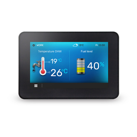
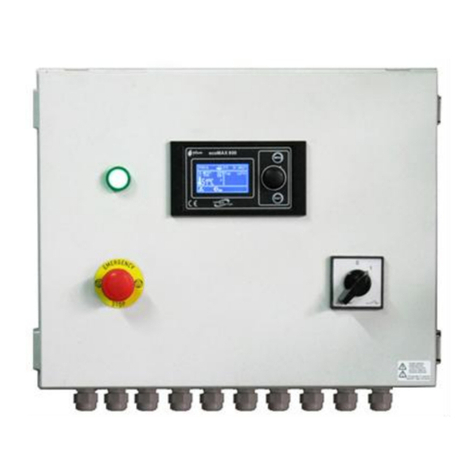
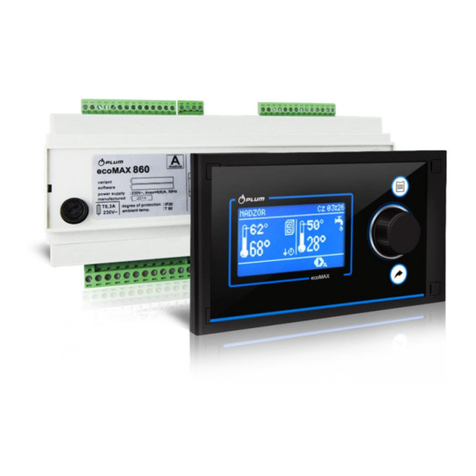
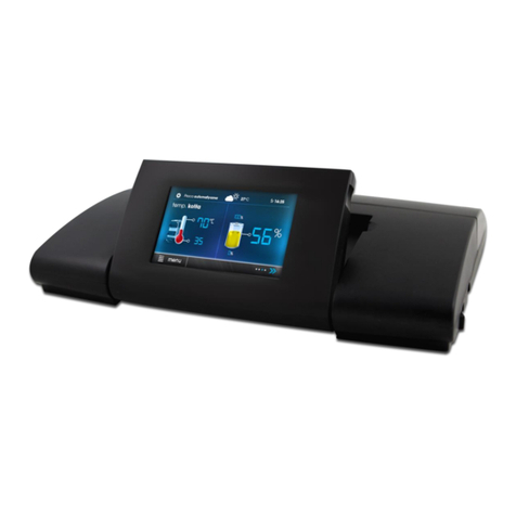
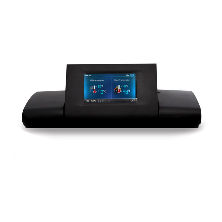
Plum ecoVENT MIDI User manual

THE CONTROLLER WITH BALANCED VENTILATION FUNCTION
ecoVENT MIDI
FOR CONTROLLING VENTILATION CENTRAL WITH MECHANICAL RECUPERATOR
* is not a standard controller equipment.
INSTALLATION AND OPERATING MANUAL
ISUUE: 1.3_EN
SOFTWARE VERSION: 03.xx
simTOUCH2
ecoTOUCH
12-2019
GHE
ecoPRESS EX1*
ecoNET300*
www.econet24.com
ecoNET.apk

2
ELECTRIC DEVICE UNDER VOLTAGE!
Before any action related to the power supply (cables
connection, device installation etc.) check if the controller is
not connected to the mains!
Installation should be done by a person with appropriate
electrical qualifications. Improper cables connection could
result in the controller damage.
The controller cannot be used in steam condensation
conditions and cannot be exposed to water.

3
TABLE OF CONTENTS
1Safety recommendations.................................... 4
2General information ........................................... 5
3Information about documentation..................... 5
4Applied symbols.................................................. 5
5DIRECTIVE WEEE 2012/19/UE............................. 5
USER MANUAL ................................................... 7
6Operating the controller..................................... 8
6.1 User menu –structure.................................... 8
6.2 CONTROLLING THE CONTROLLER ........................... 10
6.3 SWITCHING CONTROLLER ON AND OFF.................... 11
6.4 MAIN SCREENS.................................................. 12
7DESCRIPTION OF THE CONTROLLER'S OPERATION
14
7.1 CONTROLLER OPERATION MODES .......................... 14
7.2 DEVICE OPERATING MODES.................................. 15
7.3 SETTINGS OF OPERATING STATES ........................... 15
7.4 USER MODES .................................................... 16
7.5 PRESET TEMPERATURE SETTING ............................ 16
7.6 BALANCED VENTILATION FUNCTION ....................... 16
7.7 GHE SUPPORT .................................................. 16
7.8 SUPPORT OF BYPASS........................................... 17
7.9 SUPPORT OF ROTARY EXCHANGER ......................... 17
7.10 ALARM CENTRAL................................................ 17
7.11 SCHEDULES....................................................... 17
7.12 EXCHANGER CLEANING........................................ 18
7.13 GENERAL SETTINGS............................................. 18
7.14 INTERNET MODULE COOPERATION......................... 19
7.15 ALARMS AND PROMPS ........................................ 21
8Cooperation with air parameters sensors ........ 24
8.1 DIGITAL CO2LEVEL SENSOR.................................. 24
8.2 Analog CO2 level sensor ................................ 24
8.3 ANALOG HUMIDITY SENSOR ................................. 24
INSTALLATION AND SERVICE SETTINGS............. 25
9AUTOMATION SCHEMATICS ............................. 26
10 TECHNICAL DATA .............................................. 28
11 OPERATION CONDITIONS ................................. 28
12 THE CONTROLLER INSTALLATION ..................... 28
12.1 MOUNTING OF CONTROL PANEL............................ 28
12.2 MAIN MODULE INSTALLATION .............................. 30
12.3 CLEANING AND MAINTENANCE PROCEDURES ........... 31
12.4 ELECTRICAL CONNECTION .................................... 32
12.5 ELECTRICAL SCHEME ........................................... 33
12.6 Temperature sensor connection and
installation .................................................... 34
12.7 Temperature sensors testing........................ 34
12.8 CONNECTING OF DIFFERENTIAL PRESSURE SENSORS... 34
12.9 CONNECTING DIGITAL CO2LEVEL SENSOR ............... 35
12.10 CONNECTING ANALOG AIR QUALITY SENSORS........... 35
12.11 CONNECTING THE INTERNET MODULE .................... 35
12.12 VENTILATION FILTERS.......................................... 35
13 MODBUS COMMUNICATION ............................ 36
13.1 MODBUS RTU PROTOCOL ................................... 36
13.2 COMMUNICATION SETTINGS ................................ 36
13.3 READ REQUEST 0X03..........................................36
13.4 MODIFICATION REQUEST 0X06.............................36
13.5 MODIFICATION REQUEST 0X10.............................37
13.6 MODBUS TABLE .................................................38
14 INSTALLER MENU - STRUCTURE ........................43
15 MANUFACTURER MENU - STRUCTURE .............45
16 MENU - UNLOCK THE DEVICE............................46
17 DESCRIPTION OF THE INSTALLER PARAMETERS47
18 DESCRIPTION OF THE MANUFACTURER
PARAMETERS.................................................................50
19 OUTPUTS CONFIGURATION AND CONFIRMATION
OF CONFIGURATION .....................................................53
19.1 OUTPUTS CONFIGURATION FOR FAN CONVECTOR......53
20 SOFTWARE UPDATE ..........................................53
21 FILTERS SUPPORT ..............................................54
22 OTHER FUNCTIONS............................................54
22.1 UNLOCK THE DEVICE ...........................................54
22.2 POWER SUPPLY OUTAGE ......................................54
23 PARTS OR SUBASSEMBLIES REPLACEMENT.......54
23.1 MAINS FUSE REPLACEMENT ..................................54
23.2 CONTROL PANEL REPLACEMENT.............................54
4
1Safety recommendations
Requirements concerning safety are
described in detail in individual chapters of
this manual. Apart from them, apply to the
following requirements in particular.
•Before taking any actions regarding
controller: assembly, repairs or
maintenance, as well as during any
connection works, read manual and
manufacturer recommendations, please
make sure that the mains power supply
is disconnected and that terminals and
electric wires are devoid of voltage.
•After the controller is turned off using the
touch buttons, dangerous voltage still
can occur on its terminals. The controller
does not replace the electricity switch for
cooperating modules.
•Installation should be done by a person
with appropriate electrical qualifications
in accordance with technical
documentation and applicable
regulations. Improper cables connection
can result in the controller damage.
•The controller cannot be used in
conditions of water vapor condensation
and exposed to water. Provide protection
against dust and water.
•The controller is designed to be built-in.
Installation of the controller must
prevent access to hazardous parts and
ensure air exchange in the housing.
•Adjust value of programmed parameters
to specific installation type, including all
operation conditions. False adjustment
of parameters may result in emergency
state. Modification of preset parameters
should be done only by person familiar
with manual.
•Device software does not provide high
security level against false installation
operation, this should be provided by
applying external, controller
independent protections.
•It is necessary to use additional elements
to protect against the consequences of
controller malfunctions or errors in its
software.
•The controller has following procedures:
turning off heater while overheating,
which protects water heaters against
freezing, it disables fans when alarms
occur, however elements used must
have own, controller independent
protections.
•In controller power output circuits fuses
are used. Fuses value must be applied to
the load.
•The electric system in which the
controller operates must be protected by
means of a fuse, selected appropriately
to the applied loads.
•The device must be used as intended,
and within the operating parameters
range for which it has been designed.
Otherwise, the manufacturer does not
bear any responsibility for the effects
resulting from such action.
•Under no circumstances should
modifications of the controller structure
be made. It is forbidden to use a faulty
or repaired device by an unauthorized
service.
•The 230 VAC mains cables should be run
in a way that prevents them from coming
into contact with low-voltage
components.
•Cables should not come into contact with
surfaces with a temperature exceeding
the nominal operating temperature.

5
2General information
The ecoVENT MIDI controller controls the
recuperator of mechanical ventilation with a
cross-flow or rotary exchanger. Performs the
function of heat recovery from ventilated
rooms based on readings from sensors and
has the function of balanced ventilation.
Smoothly controls the air supply fan and
exhaust fan providing high efficiency of heat
recovery and air exchange in rooms based on
programmed schedules or manual control.
The controller smoothly controls additional
electric heaters, water cooler and fan
convector to provide the highest comfort and
precision regulation of ventilated air. Controls
the bypass and works with ground heat
exchanger GHE. It has the function of filters
support and detects their replacement and
overpressure/flow control function. The
controller works closely with the Web module
ecoNET300. It allows connection of external
control signals from the fire alarm system, air
quality sensors and other automation systems
through digital and analog inputs. Controller
signalizes and records emergency states
providing accurate system reaction. It saves
the cumulative operation time of individual
components into the counters and calculates
recuperator efficiency. It enables
communication via Modbus RTU protocol -
provides control and monitoring of action
controller with external building management
system. Additional function of the controller is
anti-freezing protection.
The controller can be used in households,
hotels, offices or industrialized buildings.
3Information about documentation
The controller manual is a supplement for the
recuperator manual. In particular, except for
this manual, the recuperator manual should
also be observed. The controller manual is
divided into two parts: for user and installer.
Yet, both parts contain important information,
significant for safety issues, hence the user
should read both parts of the manual.
We are not responsible for any damages
caused by failure to observe these
instructions.
4Applied symbols
In this manual the following graphic symbols
are used:
Caution: the symbols indicate important
information, in order to make the manual
more lucid. Yet, this does not exempt the user
from the obligation to comply with
requirements which are not marked with a
graphic symbol!
5Directive WEEE 2012/19/UE
Purchased product is designed and made of
materials of highest quality.
The product meets the requirements of the
Directive 2012/19/EU of 4 July 2012 on
waste electrical and electronic
equipment (WEEE), according to which it is
marked by the symbol of crossed-out wheeled
bin (like below), meaning that product is
subjected to separate collection.
Responsibilities after finishing a period of
using product:
•dispose of the packaging and product at
the end of their period of use in an
appropriate recycling facility,
•do not dispose of the product with other
unsorted waste,
•do not burn the product.
By adhering obligations of waste electrical and
electronic equipment controlled disposal
mentioned above, you avoid harmful effects
on the environment and human health.
The symbol means useful information and
tips.
The symbol means important information,
failure to observe these can cause damage of
property and threat for human health and
life.

6

7
USER MANUAL
ecoVENT MIDI

8
6Operating the controller
6.1 User menu –structure
The ecoTOUCH panel:
Operation modes device
Recuperator operation mode
•Main mode
- Pause
•Time mode:
- Off, Out, Party, Airing
Summer/Winter
- Auto, Summer, Winter,
Ventilation
•Fireplace
- No, Yes
- Velocity
•Schedules
- No, Yes
Summer/winter mode
•Summer/winter mode settings:
- Auto, Summer, Winter, Ventilation
- Winter mode on
- Hysteresis of summer mode on
Operation states settings
•User modes 1…4 settings
- Air supply,Exhaust, preset temp.
•Time modes settings
- Airing: Duration, Velocity
- Party Duration, Preset temperature,
Air supply, Exhaust
- Out: Duration
•Schedules settings
- Time 1…5
- Monday…Sunday
- Start, Stop
- Mode, Reset, Copy schedule
•Leading control sensor
- Air supply sensor, Exhaust
sensor, Panel sensor
- Panel address
User modes
Mode 1, Mode 2, Mode 3, Mode 4
Air supply, Exhaust, preset temp.
GHE*
GHE settings
•Auto, Close, Open
Summer opening temp.
Winter opening temp.
Regeneration settings
•Maximum opening time
•Regeneration time
•Manual start
Filters*
Override filters replacement procedure
- No, Yes
•Filters replacement procedure
Air supply filter –class:
- G4G5 standard
- M5/M6 medium
- F7/F8 accurate
Exhaust filter –class:
- G4G5 standard
- M5/M6 medium
- F7/F8 accurate
Was air supply filter replaced?
- Yes, No
Was exhaust filter replaced?
- Yes, No
•Was filters replacement procedure
finished?
- Yes, No
Bypass/Heat recovery
Open, Closed, Auto, No recovery,
Maximum recovery, Auto*
Alarm central
Alarm central support
Logical state, NO, NC
Recuperator reaction
•Recuperator off, Exhaust, Air supply
Airing: YES, NO
Exchanger cleaning
Cleaning start hour
General settings
Language
Date
Clock
Brightness

9
Screen saver settings
•On/Off screen saver
•Time till screen saver
•Screen saver backlight
Button sound
Alarms sound
Default settings
Software update
Parental control
Address setting
ecoNET settings*
SSID
WiFi encryption type
Password
Alarms
Service settings
Information
Turn on/off controller
The simTOUCH2 panel:
Information
Operation modes device
Operation mode
•Pause, Mode 1, Mode 2, Mode 3,
Mode 4
Timed operation mode
•Off, Out, Party, Airing
Summer/Winter
•Auto, Summer, Winter, Ventilation
Fireplace function
•No, Yes, Speed
Operation states settings
•Party mode settings
➢Party duration
➢Air supply fan speed
➢Exhaust fan speed
➢Preset temperature
•Airing mode settings
➢Airing duration
➢Fan speed
•Out mode duration
•Fireplace mode settings
➢Speed
•Exit mode time
•Winter mode activation
•Hyst. of turn. on summer mode
•1…4 User mode
➢Preset temperature
➢Air supply fan speed
➢Exhaust fan speed
•Schedules
➢Schedules support
➢Schedule
Preset temperature
Preset temperature*
Control leading sensor
➢Air supply sensor
➢Exhaust sensor
➢Panel sensor
Panel address*
GHE*
GHE control
➢Close, Open, Auto
Summer opening temp.
Winter opening temp.
Regeneration settings
➢GHE max. duration
➢GHE regeneration time
➢Reg. manual start
Filters*
Override filters replacement procedure
➢- No, Yes
Filters replacement procedure
Air supply filter –class:
- G4G5 standard
- M5/M6 medium
- F7/F8 accurate
Exhaust filter –class:
- G4G5 standard
- M5/M6 medium
➢- F7/F8 accurate
Was air supply filter replaced?
➢- Yes, No
Was exhaust filter replaced?
➢- Yes, No
•Was filters replacement procedure
finished?
➢- Yes, No
Bypass/Heat recovery*
No recovery, Max. recovery, Auto
Close, Open, Auto*
General settings
Button sound
Alarm volume
Alarm sounds
Screen saver settings
•Time till screen saver
•Screen saver mode
➢Off, On, Clock
Individual menu options may be unavailable
without proper sensor, device, menu setting
or if controller is off. Such options are marked
with “*”.

10
ecoNET settings
➢WiFi encryption type
➢WiFi Name
➢WiFi Password
Address settings
Brightness
Contrast
Language
Date and Clock
Default settings
Panel software update
Controller software update
Alarm system settings
Alarm system support
Input logical state
Recuperator reaction
•Turn off recuperator, Velocity change
Airing function
•Air supply fan speed
•Exhaust fan speed
•Airing duration
•Cyclic airing time
•Af. heat. work
Exchanger cleaning*
Time of cleaning start
Service settings
6.2 Controlling the controller
The ecoTOUCH panel:
A touch screen has been used to control the
device.
Settings change is done using rotary menu.
Selection and edit in the menu is done by
pressing desired symbol on the screen.
Grouped parameters from the selected menu
are displayed on one screen. An example of
such parameters grouping is shown in the
figure below.
On-screen symbol meanings:
- return to the previous menu or
no acceptance of parameter setting.
- fast return to the main screen from
each menu level.
- information about selected
parameter.
- main menu;
–decrease or increase parameter
value;
-service menu;
- sliding list of parameters;
Individual items of the menu may not appear if
there is no suitable sensor, devices, menu settings
or the controller is turned on. These positions are
marked with “*” symbol.

11
- enter selected menu option or accept
selected parameter setting.
- decrease or increase value of
the on-screen selected parameter.
The simTOUCH2 panel:
The controller is operated via touch buttons
that allow selecting items from the menu and
edition of parameters.
Buttons description:
1. MENU - entry button.
2. The parameters selection from the list
button, increases the value of the edited
parameter and switches between main
screens.
3. ENTER –confirmation.
4. EXIT.
5. The parameter selection from the list
button, reduces the value of the edited
parameter and switches between the
main screens.
6.3 Switching controller on and off
The ecoTOUCH panel:
After switching on the controller recalls its
status from the moment of switching it off. If
the controller was not active before, it will
start in the “Stand-by” mode. In this mode it
displays the current date and time, external
temperature and information: “Recuperator
turned off”.
To start the controller, press anywhere on the
screen, then the following message will
appear: “Turn on the recuperator?”.
There is also another method of controller
turn on. Press Menu button, find and press
symbol in a pie menu. To turn off
the controller - press Menu button,
press symbol a
find and
in pie menu.
The simTOUCH2 panel:
After switching on the controller recalls its
status from the moment of switching it off. If
the controller was not active before, it will
start in the “Stand-by” mode. In this mode it
displays the current date and time, external
temperature and information: “Recuperator
turned off”.
To start the controller, touch the button,
then a message will appear: "Turn on the
recuperator?". Confirm by pressing again,
which turns the controller on.
To turn off the controller, on any of the main
screens, touch the button and confirm
to turning the controller off.

12
6.4 Main screens
The ecoTOUCH panel:
The controller has two main screens. First: with the displayed parameters and operation modes,
with the function of editing and reading information, second: with automation scheme displayed.
The view between these screens can be switched.
Main screen with options to read information and change selected parameters.
1. Settings for main mode and user
modes.
2. Additional mode selection.
3. Main menu access.
4. Information field, e.g.: Active alarms -
press to display a list of all current
alarms.
5. Schedules settings.
6. Switching between main screens.
7. Basic information –press to display all
available information about controller
operation status.
Main screen with cross-flow exchanger.
The values shown in the screen are only
indicative.

13
Main screen with rotary exchanger.
Legend:
1. Regulation modes: OPERATION,
OPERATION-Heating, OPERATION-
Cooling, DEFREEZING, PAUSE, Exchanger
cleaning, Heater cooling, Airing.
2. Exhaust fan adjustment:
- exhaust fan work (along with the
current control);
3. Exhaust temperature.
4. Operation of the heater primary electricity
or water.
5. Intake temperature (outside temp.).
6. Ground heat exchanger throttle actuator
position.
7. Ground heat exchanger (GHE).
8. GHE temperature.
9. Bypass throttle actuator position.
10. Information:
[R1], [R2] –exceeding the demand for
expenditure change threshold;
[SAP] –signal from the fire control unit;
[ECO] –signal from the alarm central;
[TR1] –primary heater thermostat trip
[TR2] –secondary heater thermostat trip;
11. Extraction temperature;
12. Preset temperature;
13. Air supply temperature;
14. Cooler work (Freon- or water-);
15. Working secondary heater (electrical- or
water-).
16. Time and working day.
17. Supply fan control:
- supply fan work (along with the
current control).
18. Position of the mixer actuator.
Automation schemes presented on the main screen can be different depending on whether there
are individual ventilation system devices connected to the controller e.g.: throttles, heaters, and
values display are for information purposes only.

14
The simTOUCH2 panel:
The controller has two main screens:
information screen with basic parameters and
automation scheme screen. Switching
between screens is done by touching the (2)
and (5) buttons.
Information screen.
Main screen with cross-flow exchanger.
Main screen with rotary exchanger.
Legend:
1. Regulation modes: OPERATION,
OPERATION-Heating, OPERATION-
Cooling, De-freezing, Pause, Exchanger
cleaning and water removal, Airing, Heater
cooling.
2. Preset air supply temperature.
3. Measured air supply temperature.
4. Supply fan speed.
5. Exhaust fan speed.
6. Information field of measured
temperatures.
7. Time and working day.
8. Operation modes: Pause, Mode 1…4
(U1...4).
9. Information:
- summer mode active
- fireplace mode.
10. Exhaust temperature.
11. Exhaust.
12. GHE temperature and the position of
the actuator.
GHE: - OFF, - ON
13. Intake.
14. Intake temperature (outside).
15. Information:
ALARM –alarm signaling
- operation of the primary heater
- secondary heater operation
- cooler operation
16. Position of the bypass actuator.
17. Position of the mixer chamber actuator.
18. Extraction temperature.
19. Extraction.
20. Supply.
21. Supply temperature.
7Description of the controller's
operation
7.1 Controller operation modes
The controller operation modes according to
which ventilation is adjusted.
•OPERATION –the controller, including
user settings, controls the ventilation to
achieve the preset temperature in the
room.
•OPERATION-Heating –the controller,
disregarding low external temperature,
seeks to keep preset temperature in the
room; to achieve it first selects the source
with the highest available air temperature,
then depending on fulfilling conditions,
starts secondary heater.
•OPERATION-Cooling - the controller,
disregarding high external temperature,
seeks to keep preset temperature in the
room; to achieve it first selects the source
with the lowest available air temperature,

15
then depending on fulfilling conditions,
starts the cooler.
•Defrosting –the controller prevents
exchanger to freeze, by adjusting fans
speed and starting primary heater.
•Pause –the controller stops recuperator
operation, only protection functions are
operational.
•Exchanger cleaning - the controller
activates the cleaning mode by switching
on the fans to maximum power.
•Exchanger dehydration –controller starts
exchanger dehydration function, while
holds fans operation.
•Heater cooling - the controller sustains air
supply fan work for a set time, to cool
electric heaters.
•Airing - the controller turns on airing
function.
7.2 Device operating modes
Settings regarding controller operation
modes, according to which control will be
performed, are in the menu:
Menu →Operation modes
Menu →Operation modes device
The ecoTOUCH screen allowing setting of
active controller functions is in the menu:
Menu →Operation modes →Recuperator
operation modes
•Recuperator operation mode (Operation
mode) –recuperator mode settings.
Selecting Pause mode will stop
recuperator, only protection functions stay
active. This mode can be applied to
prevent unpleasant odors from the
outside. It is possible to select one of
modes Mode 1…4, settings of which can be
defined by user.
•Time mode (Timed operation mode) –
turning on one of the additional
recuperator operation modes. Available
settings:
- Off: turn off active time mode.
- Output mode: holds on recuperator
operation, this mode can be applied e.g.
for a period of leaving the room by user.
- Party mode: increases fans expenditure
and amends preset temperature value,
this mode can be applied e.g. during the
presence of large number of people in the
room.
- Airing mode: amends exhaust fan
expenditure, while turning off air supply
fan, this mode can be applied e.g. for fast
air exchange in the room.
•Summer/winter (Summer/winter mode) –
recuperator control mechanism setting
- Winter mode: blocks cooler and Bypass.
- Auto mode: selection of active
mechanism according to settings and
external temperature
- Ventilation: blocks cooler and heaters.
•Fireplace (Fireplace function) –allows
turning on fireplace function. If this
function is on the control of exhaust fan
will be depending on air supply speed and
preset difference in Speed parameter.
•Schedules –allows turning on controller
according to user defined schedules.
The ecoTOUCH screen allowing setting of
control mode is in the menu:
Menu →Operation modes →
Summer/winter
•Setting mode according to which the
control will be performed. Similarly to
Summer/winter menu into
Recuperatio operation mode menu.
•Winter mode turn on –temperature value
below which, with auto mode active,
winter mode will be turned on.
•Hysteresis of summer mode on –
hysteresis value of mode amendment, if
auto mode is active and external
temperature increases above Winter mode
turn on + Hysteresis of summer mode on
the summer mode will be activated.
7.3 Settings of operating states
Settings related to operation modes, timed
modes and additional operating states of the
controller, during which we change the control
status of the ventilation unit for a specified
period of time, can be found in the menu:
Menu →Operation modes → Operation
states settings
Menu →Operation modes device →
Operation states settings
•User modes settings –redirects to user
modes settings, described in item 7.4

16
•Time modes settings –menu allows to
define time modes settings, for Airing
mode it is possible to set mode duration
time (Duration time parameter), preset
temperature (Preset temp. parameter),
fans speed: air supply (Air supply
parameter) and exhaust (Exhaust
parameter), for Out mode it is possible to
set its duration time (Duration time
parameter).
•Schedules settings –redirects to
schedules setting panel, described in item
7.11
•Control leading sensor –setting, according
to which sensor the remote temperature
control is performed, available: Air control
sensor, Exhaust sensor, Panel sensor.
•Panel address –if leading sensor is set to
panel sensor, then panel address, from
which temperature value is read, must be
set.
7.4 User modes
Menu allows individual setting, for each user
mode 1…4, air supply speed (Air supply),
exhaust speed (Exhaust) and preset
temperature in Preset temp. parameter.
7.5 Preset temperature setting
The preset temperature of the recuperator is
set in the menu:
Menu →Preset temperature
Additionally, it is possible to set, according to
which sensor the temperature control will be
adjusted by the parameter Control leading
sensor. Available for selection are: Supply
sensor, Extraction sensor and Panel Sensor
allowing defining address of the panel with
leading sensor.
7.6 Balanced ventilation function
The controller has balanced ventilation
function that adjusts the flow of air flow and
pressure in ventilation ducts. The function
allows to increase the efficiency of heat
recovery, system resistance e.g. against air
filter dirtying, exchanger resistances change
due to humidity or dirt, starting air flow via
ground heat exchanger.
The function turn on and configuration is done
in Installer menu.
7.7 GHE support
The controller supports ground heat
exchanger (GHE) as a part of the ventilation
system. The ground temperature is used here,
which is higher than air temperature for the
most part of the year.
The GHE support parameter allows selection
GHE operation mode:
•Close –the controller turn off glycol pump
or closes the throttle cutting off the air
flow via GHE.
•Open –the controller turn on glycol pump
or opens the air throttle on the GHE pipe
GHE.
•Auto - the controller turns on or off GHE
depending on preset user settings,
external temperature and GHE
temperature. Turn on can be done in two
modes: heating mode –winter turn on and
in cooling mode –summer turn on. Winter
turn on of GHE will be performed if
external temperature drops below Winter
opening temp. and while GHE sensor
temperature is higher than temperature
on external temperature sensor. Summer
opening will be performed if external
temperature increases above Summer
opening temp. and while GHE sensor
temperature is lower than temperature on
external temperature sensor.
In case of no GHE temperature sensor
connected or its support is off in installer
menu, the GHE control will depend on only
The balanced ventilation function requires the
connection of differential pressure sensors.
GHE support requires connection of external
temperature sensor.
The external temperature value is measured
by a temperature sensor mounted on an
intake.

17
from the external temperature sensor
readings.
Additional GHE control settings are in the
menu:
Menu →GHE →Control settings
•GHE max. opening time –maximum
duration of GHE throttle opening. After
that time the GHE regeneration procedure
will start.
•GHE regeneration time –duration of the
GHE regeneration. During regeneration
process the GHE throttle remains closed.
•Manual start –manual start of the
regeneration without waiting for the
fulfilment of the temperature and time
condition.
7.8 Support of Bypass
The Bypass menu contains settings related to
the bypass and allows selecting control type
for the cross-flow exchanger bypass throttle.
The throttle can be constantly open (Open
parameter –no heat recovery and exchanger
freezing risk), constantly closed (Close
parameter) or in auto mode (Auto
parameter), during which throttle will be open
depending on fulfilment of open conditions.
When bypass is open the inner rooms can be
cooled to preset temperature using cooler air
from the outside.
7.9 Support of rotary exchanger
The Heat recovery menu contains settings
related to the rotary exchanger.
The rotary heat exchanger can be constantly
stopped (No recovery parameter) or rotate at
the maximum speed (Maximum recovery
parameter). The rotary exchanger can be also
controlled according to controller’s algorithm
with Auto parameter. If the rotary exchanger
is stopped, the air inside the room is cooled to
preset temperature using air from the outside.
7.10 Alarm central
Settings related to supporting signal from
alarm central. After receiving signal from the
alarm central the fans expenditure will be
changed according to the following menu
settings:
Menu →Alarm central
•Alarm central support –turns on/off alarm
central support. If the function is active,
then after receiving signal from alarm
central the controller operation will be
amended according to alarm central
settings.
•Logical state –setting logical state of
digital input: NO (normally open) or NC
(normally closed).
•Recuperator reaction –setting the
recuperator reaction to central alarm
signal. If Turn off recuperator is selected,
then after receiving signal the recuperator
will be turned off. Otherwise, fans speed
will be amended to the settings defined by
Exhaust and Air supply.
•Airing –turn on/off airing function, it
works only with central control mode on
and Turn off recuperator option off.
The airing settings are in the following menu:
Menu →Alarm central settings → Airing
settings
•Exhaust fan speed, Air supply fan speed –
allow setting fans speed during airing.
•Airing time –parameter defining time,
through which airing is performed.
•Periodic airing time –this parameter
defines time periods between succeeding
airing cycles.
•Secondary heater work during airing –
turning on/off permission of secondary
heater to work during airing.
7.11 Schedules
The menu allows to set the schedules of the
recuperator work.
The ecoTOUCH panel:
Programmed schedule is stored in internal
memory and is not deleted during the power
outage.

18
Schedules support can be turned on in two
ways: via Schedules parameter, in the menu:
Menu →Operation modes → Recuperator
operation modes
or via Schedules parameter, in the menu:
Menu →Operation modes → Operation
modes settings → Schedules settings
In schedules menu 5 ranges of ventilation
central work can be set for each day of the
week (Time 1…5). For each range the duration
time must be set (Start and Stop parameters:
hours and minutes) and active work mode
chosen (Mode parameter).
The button allows to copy currently
defined schedule to any day of the week.
The simTOUCH2 panel:
The menu allows to set the schedules of the
recuperator.
Available Time schedules support in the
menu:
Menu →Operation modes device → Work
modes settings → Time schedule
is responsible for changing the main operation
mode of the recuperator. Set the parameter
to ON.
Up to 5 ranges (T1...T5) can be set for the
selected day of the week to operate the
ventilation system. For each range, set the
schedule activation (Start, Stop parameters:
hours and minutes) and select the active
operation mode (Mode parameter).
Icon allows to copy currently defined
schedule to any day of the week. Res icon
clears set schedule.
7.12 Exchanger cleaning
Cleaning start hour parameter allows setting
the moment to start cleaning. The procedure
will be started at the preset hour after
reaching cleaning day.
7.13 General settings
The menu contains settings for user to set,
related to general controller settings.
The ecoTOUCH panel:
•Alarms sound –enable or disable
alarms sound.
•Language –language selection.
•Date –setting the date. After
entering the date a day of the week will be
set automatically.
•Clock –setting the hour. Changing
time in any room panel will trigger time
change in the controller.
•Brightness –allows changing
screen brightness.
•Button sound –enable or disable
the sound while pressing the touch screen.
•Software update - software update
of controller module and control panel.
Description later in the manual.
•Address setting - allows assigning
a unique address of the control panel for
the bus, with many room panels
connected to the controller.

19
•Parental control –when turned on
it blocks entering to the menu. Unlock by
pressing the screen for 3 sec. (open
padlock animation).
•ecoNET settings –a WiFi network
configuration in case of connecting
ecoNET300 internet module to the
controller. SSID –network identifier must
be entered, WiFi security chosen and
password for selected WiFi network
entered. Further module configuration
should be carried out in accordance with
operation and maintenance
documentation for ecoNET300.
•Screen saver settings –setting
Screen saver On/Off parameter to YES will
dim or turn off the screen after set time.
Time delay to start the screen saver is set
with Time till screen saver parameter. The
backlight value during active screen saver
mode is set with Screen saver backlight
parameter.
•Default settings –restores the
default settings of the panel and controller
parameters to the customer.
The simTOUCH2 panel:
•Button sound –turn on or off the sound of
pressing the keys.
•Alarm volume –loudness of the alarm
signal.
•Alarm sound –enable or disable alarms
sound.
•Screen saver settings –set the time to
start the screen saver in the Time till
screen saver parameter. In the parameter
Screen saver mode, can select the screen
saver mode for: Off, On or Clock.
•ecoNET settings –a WiFi network
configuration in case of connection an
internet module ecoNET300 to the
controller. Enter SSID –network identifier,
select type of WiFi protection and enter
password for selected WiFi network.
•Address settings –setting a unique panel
address for proper communication with
module in case of connecting additional
panels.
•Brightness –allows changing screen
brightness.
•Contrast –contrast of the screen.
•Language –language selection.
•Clock and Date –time and date setting.
After entering the date, the day of the
week will automatically be set.
•Software update - software update in all
devices connected to the controller
module. Description later in the manual.
7.14 Internet module cooperation
The ecoNET300 internet module enables
remote maintenance of controller operation
via Wi-Fi or LAN network, using
www.econet24.com service.
Using computer, tablet or smartphone with
web browser installed or convenient
application for mobile devices ecoNET.apk.
user can remotely monitor the controller and
modify its working parameters. The
application can be downloaded free of charge
from:
To ensure the correct system operation the
control panel addresses must be from
address pool 100…132.
Internet module will control the controller
only with control panel connected to the
module.

20
Table of contents
Other Plum Controllers manuals

Plum
Plum ecoMAX860P1-K STANDARD User manual

Plum
Plum ecoMAX860P3-C TOUCH User manual

Plum
Plum Cieplo ecoMAX850P2-C User manual

Plum
Plum ZAB-07 User manual

Plum
Plum ecoMAX850P1-R User manual

Plum
Plum ecoMAX810P3-L TOUCH User manual

Plum
Plum ecoMAX860P3-LZ User manual

Plum
Plum ecoMAX920P1-S TOUCH User manual

Plum
Plum ecoMAX860P3-C TOUCH User manual

Plum
Plum ecoMAX920P1-K User manual