manuals.online logo
Brands
  1. Home
  2. •
  3. Brands
  4. •
  5. Potter
  6. •
  7. Security Sensor
  8. •
  9. Potter PAD300-HD User manual

Potter PAD300-HD User manual

PAD300-HD
Contents
A. Introduction E. Addressing
B. Specications F. Testing
C.Installation G. Warranty
D. Locking Feature
e PAD300-HD is an intelligent addressable thermal detector
with a programmable xed temperature and a 15F/min rate
of rise alarm.
Each detector includes one (1) LED to indicate the device
status. e LED ashes momentarily in normal conditions and
ashes at a fast rate when activated. e LED can be turned o
using the programming soware.
e PAD300-HD is listed on maximum 70  spacing with
alarm set point from 135F to 185F on smooth ceiling.
Refer to NFPA 72 for specic information regarding detector
spacing, placement and special applications.
e PAD300-HD communicates on a proprietary protocol to
the addressable re alarm control panel. It must be connected
to either the IPA series, AFC series, or ARC re alarm
control panel for proper operation. For detector sensitivity
settings and supervision, please refer to the panel installation
instructions.
Refer to the company website for the latest revision of this
manual.
A. Introduction
1609 Park 370 Pl, Hazelwood, MO 63042
www.pottersignal.com
PAD300-HD
Operating Voltage 24 VDC
Standby Current (*) 300 A
Alarm Indicator Current 1.4 mA
Alarm Temp Rating
Installation Temp Range
135F to 174F
32F to 115F
Alarm Temp Rating
Installation Temp Range
175F to 185F
32F to 150F
Operating Humidity Range 0% - 93% (Non-condensing)
Dimension Φ 3.93 in
Weight 2.4 oz
Height 1.5 in
*Standby current is the current the device consumes when the device
is in a non-activated condition and where no communication current
is transmitted to the re alarm control panel.
Sensitivity-Spacing Allocation:
e sensitivity of PAD300-HD heat detector is expressed in
terms of spacing limitations. Spacing limitations refer to the
maximum distance permitted between heat detectors mounted
on smooth ceilings.
See below table for the UL521 spacing limitations.
Spacing Allocation
Fixed Temperature 135ºF to
185F 70 
w/ Rate of Rise 15F/min 70 
NOTE:THE DEFAULT FIXED ALARM TEMPERATURE IS 135F
WITH THE RATE-OF-RISE FUNCTION DISABLED. BOTH SET-
TINGS CAN BE CHANGED IN THE POTTER PROGRAMMING
SOFTWARE. FOR FURTHER INFORMATION, REFER TO THE
CONTROL PANEL INSTALLATION INSTRUCTIONS.
B. Specications
Installation must meet the requirements of the Authority
Having Jurisdiction (AHJ). It is recommended to follow
guidelines as described in NFPA 72.
1. Before connecting a device to the SLC loop, take the
following precautions to prevent potential damage to the
SLC or device.
• Use only the PAD300 series bases PAD300-4DB,
PAD300-6DB, PAD300-SB, PAD300-LFSB (supplied
separately).
• Conrm the eld wiring on device is correctly
installed on the base. Refer to the base manual.
• Enable the locking feature if needed. Refer to section
D for details of the locking feature.
2. Set the desired address using the DIP switch located
on back of the sensor. See section E for addressing
instructions.
3. Plug detector into base and turn clockwise to secure in
place.
C. Installation
e device includes a tamperproof feature that locks the detec-
tor and does not allow removal without the use of a tool.
D. Locking Feature
Break o tab (gray area in
image). e locking feature
is enabled.
Insert a small
screwdriver into slot
to remove detector.
DETECTORS ARE NOT TO BE USED WITH
DETECTOR GUARDS UNLESS THE COMBINATION HAS BEEN
EVALUATED AND FOUND SUITABLE FOR THAT PURPOSE.
E. Addressing
Detector address can be congured using the
table below for DIP switch position settings.
POS DIP Switch on POS DIP Switch on POS DIP Switch on
1 1 43 1,2,4,6 85 1,3,5,7
2 2 44 3,4,6 86 2,4,5,7
3 1,2 45 1,3,4,6 87 1,2,3,5,7
4 3 46 2,3,4,6 88 4,5,8
5 1,3 47 1,2,3,4,6 89 1,4,5,7
6 2,3 48 5,6 90 2,4,5,7
7 1,2,3 49 1,5,6 91 1,2,4,5,7
8 4 50 2,5,6 92 3,4,5,7
9 1,4 51 1,2,5,6 93 1,3,4,5,7
10 2,4 52 3,5,6 94 2,3,4,5,7
11 1,2,4 53 1,3,5,6 95 1,2,3,4,5,7
12 3,4 54 2,3,5,6 96 6,7
13 1,3,4 55 1,2,3,5,6 97 1,6,7
14 2,3,4 56 4,5,6 98 2,6,7
15 1,2,3,4 57 1,4,5,6 99 1,2,6,7
16 5 58 2,4,5,6 100 3,6,7
17 1,5 59 1,2,4,5,6 101 1,3,6,7
18 2,5 60 3,4,5,6 102 2,3,6,7
19 1,2,5 61 1,3,4,5,6 103 1,2,3,6,7
20 3,5 62 2,3,5,5,6 104 4,6,7
21 1,3,5 63 1,2,3,4,5,6 105 1,4,6,7
22 2,3,5 64 7 106 2,4,6,7
23 1,2,3,5 65 1,7 107 1,2,4,6,7
24 4,5 66 2,7 108 3,4,6,7
25 1,4,5 67 1,2,7 109 1,3,4,6,7
26 2,4,5 68 3,7 110 2,3,4,6,7
27 1,2,4,5 69 1,3,7 111 1,2,3,4,6,7
28 3,4,5 70 2,3,7 112 5,6,7
29 1,3,4,5 71 1,2,3,7 113 1,5,6,7
30 2,3,4,5 72 4,7 114 2,5,6,7
31 1,2,3,4,5 73 1,2,4,7 115 1,2,5,6,7
32 6 74 3,4,7 116 3,5,6,7
33 1,6 75 1,3,4,7 117 1,3,5,6,7
34 2,6 76 2,3,4,7 118 2,3,5,6,7
35 1,2,6 77 1,3,4,7 119 1,2,3,5,6,7
36 3,6 78 2,3,4,7 120 4,5,6,7
37 1,3,6 79 1,2,3,4,7 121 1,4,5,6,7
38 2,3,6 80 5,7 122 2,4,5,6,7
39 1,2,3,6 81 1,5,7 123 1,2,4,5,6,7
40 4,6 82 2,5,7 124 3,4,5,6,7
41 1,4,6 83 1,2,5,7 125 1,3,4,5,6,7
42 2,4,6 84 3,5,7 126 2,3,4,5,6,7
127 1,2,3,4,5,6,7
Testing must meet the requirements of the Authority Having
Jurisdiction (AHJ). It is recommended to follow guidelines as
described in NFPA 72.
It is important to test the product aer installation and
periodically to ensure it functions probably.
Heat Test
Use hair dryer or heat gun to direct the heat toward the side
of the detector. Keep at a distance of 6 in or 15 cm to avoid
overheating.
Units failing the heat test should be serviced.
Magnet Test
e magnet test provides a quick test to verify the connections
and the detector electronically. is test should not replace the
aerosol test, which is required as part of regular testing and
maintenance per NFPA 72.
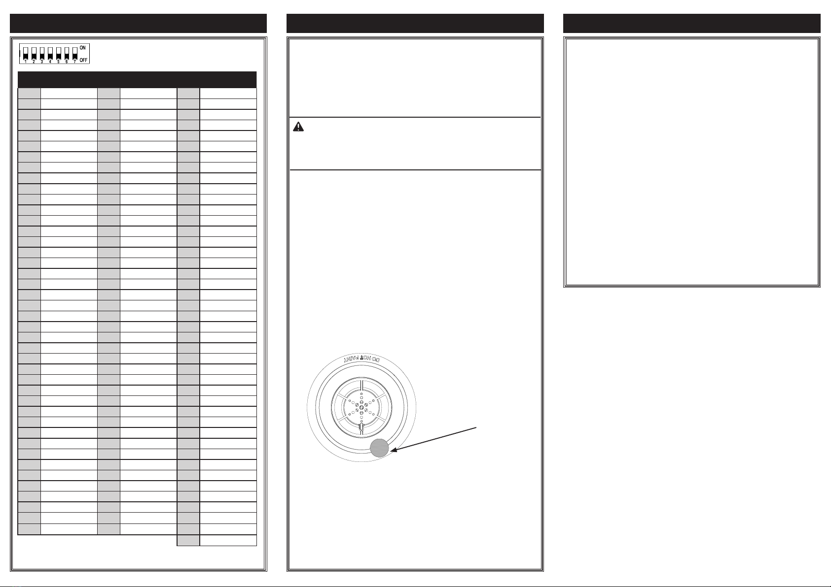
1. Hold the test magnet in the magnet test area as shown
below.
2. e LED ashes rapidly to indicate the detector is in
alarm.
3. Remove magnet.
4. Alarm on the re alarm panel should be reset.
5. Unit failed the magnet test should be tested again
with heat gun or hair dryer to conrm the failure.
F. Testing
NOTIFY APPROPRIATE AUTHORITY BEFORE
TESTING THE DETECTOR. PLACE FIRE PANEL IN
WALK TEST
MODE BEFORE CONDUCTING THE FOLLOWING TEST. REFER
TO THE PANEL INSTALLATION MANUAL FOR DETAIL.
CAUTION
Magnet Location
POTTER warrants that the equipment herein shall conform
to said descriptions as to all armation of fact and shall be
free from defects of manufacture, labeling, and packaging for
a period of ve (5) years from the invoice date to the original
purchaser, provided that representative samples are returned
to POTTER for inspection. e product warranty period is
stated on the exterior of the product package. Upon a de-
termination by POTTER that a product is not as warranted,
POTTER shall, at its exclusive option, replace or repair said
defective product or parts thereof at its own expense, except
that Purchaser shall pay all shipping, insurance, and similar
charges incurred in connection with the replacement of the
defective product or parts thereof. is Warranty is void in
the case of abuse, misuse, abnormal usage, faulty installation,
or repair by unauthorized persons, or if for any other reason
POTTER determines that said product is not operating prop-
erly as a result of causes other than defective manufacture,
labeling, or packaging.
G. Warranty
Manual Number:
54035210X_A
Manual Issue Date:
07/01/2022

Other Potter Security Sensor manuals

Potter EVD-2 User manual

Potter

Potter EVD-2 User manual

Potter RA-6500R User manual

Potter

Potter RA-6500R User manual

Potter Amseco EBP-401 User manual

Potter

Potter Amseco EBP-401 User manual

Potter PAD200-DUCT User manual

Potter

Potter PAD200-DUCT User manual

Potter PAD100-DUCT User manual

Potter

Potter PAD100-DUCT User manual

Potter PAD200-DUCTR User manual

Potter

Potter PAD200-DUCTR User manual

Potter IDC-6 User manual

Potter

Potter IDC-6 User manual

Potter PAD100-IB User manual

Potter

Potter PAD100-IB User manual

Potter PAD300-IB User manual

Potter

Potter PAD300-IB User manual

Potter amseco SB24 Series User manual

Potter

Potter amseco SB24 Series User manual

Potter RA-6006 User manual

Potter

Potter RA-6006 User manual

Potter PAD300-RB User guide

Potter

Potter PAD300-RB User guide

Potter PAD300-CD User manual

Potter

Potter PAD300-CD User manual

Potter PAD100-PD User manual

Potter

Potter PAD100-PD User manual

Potter PAD300-DD User manual

Potter

Potter PAD300-DD User manual

Potter CS-24 Series User manual

Potter

Potter CS-24 Series User manual

Potter PAD100-LFSB User manual

Potter

Potter PAD100-LFSB User manual

Potter PAD300-4DB User manual

Potter

Potter PAD300-4DB User manual

Potter Amseco EBP-401 Quick start guide

Potter

Potter Amseco EBP-401 Quick start guide

Potter PAD100-DUCTR User manual

Potter

Potter PAD100-DUCTR User manual

Potter PAD300-SB User manual

Potter

Potter PAD300-SB User manual

Potter EVD-1 User manual

Potter

Potter EVD-1 User manual

Potter PAD100-RB User manual

Potter

Potter PAD100-RB User manual

Potter LFH-24 Series User manual

Potter

Potter LFH-24 Series User manual

Popular Security Sensor manuals by other brands

netvox RA02C user manual

netvox

netvox RA02C user manual

Visonic GB-502 PG2 installation instructions

Visonic

Visonic GB-502 PG2 installation instructions

Powerfix Profi 285131 Operation and safety notes

Powerfix Profi

Powerfix Profi 285131 Operation and safety notes

MaxLite EXC-GW installation instructions

MaxLite

MaxLite EXC-GW installation instructions

AMC PROXIMITY KX-PB installation guide

AMC

AMC PROXIMITY KX-PB installation guide

RAB Lighting SmartBox installation manual

RAB Lighting

RAB Lighting SmartBox installation manual

Atim Cloud Wireless ACW/LW8-CTS user guide

Atim Cloud Wireless

Atim Cloud Wireless ACW/LW8-CTS user guide

NookBox E6309661 installation guide

NookBox

NookBox E6309661 installation guide

AJAX GlassProtect user manual

AJAX

AJAX GlassProtect user manual

LEGRAND 0 488 06 quick start guide

LEGRAND

LEGRAND 0 488 06 quick start guide

SICK WEU 26/2 Technical description

SICK

SICK WEU 26/2 Technical description

Spectrex SharpEye 40/40 Series quick start guide

Spectrex

Spectrex SharpEye 40/40 Series quick start guide

PDi NC-120 Operation manual

PDi

PDi NC-120 Operation manual

Vision ZD2105IN-5 Installation & operation manual

Vision

Vision ZD2105IN-5 Installation & operation manual

TPI 720B User m manual

TPI

TPI 720B User m manual

tau TAU-AC-900-PIVOT installation guide

tau

tau TAU-AC-900-PIVOT installation guide

Optex RLS-50100V Important product information

Optex

Optex RLS-50100V Important product information

DELTA DORE TYXAL DOI PVC installation guide

DELTA DORE

DELTA DORE TYXAL DOI PVC installation guide

manuals.online logo
manuals.online logoBrands
  • About & Mission
  • Contact us
  • Privacy Policy
  • Terms and Conditions

Copyright 2025 Manuals.Online. All Rights Reserved.