Power Craft PAG-230/2100K User manual

Servotool • Lingenstraat 6 • 8028 PM Zwolle NL • www.ferm.com UK-0507-05
UK Subject to change
UK USERS MANUAL
Art.nr. AGM6011
PAG-230/2100K
Angle Grinder

Powercraft 11
EXPLODED VIEW
Fig.1
Fig.2
Fig.3
Fig.4
Fig.5
+
2Powercraft
14 13
8
7
8
6
1
2
7
5
4
12
11
4
10
9
3
3

10 Powercraft
Fig.6
Fig.7
Fig.8
30 - 40o
Powercraft 3
SPARE PARTS LIST PAG-230/2100K
PC NR DESCRIPTION REF NR
406941 FLANGE OUTSIDE 1
406940 FLANGE INSIDE 3
407015 WHEEL COVER 4 TILL 6
406943 SPINDLE GEAR 18
406944 PINION GEAR 28
407016 ROTOR 32
407017 STATOR 35
406947 BRUSH HOLDER 42
406948 CARBON BRUSH SET (2 PCS) 43
406949 BRUSH CAP 44
406950 SWITCH 51
406877 SIDE HANDLE 60
406814 CAM WRENCH 61

Powercraft 9
ANGLE GRINDER
THE NUMBERS IN THE FOLLOWING TEXT
CORRESPOND WITH THE PICTURES AT PAGE
2+3
CONTENTS:
1. Machine data
2. Safety instructions
3. Assembly
4. Use
5. Service & maintenance
1. MACHINE DATA
INTRODUCTION
This machine is developed for grinding and roughing of
metal and stone.
PACKAGE CONTENTS
1 Angle grinder
1 Side handle
1 Spanner
1 Set carbon brushes
1 Instruction manual
1 Warranty card
TECHNICAL SPECIFICATION
FEATURES
Fig.1
1. On/off switch
2. Screw-on lid carbon brush (both sides)
3. Spindle lock
4. Grinding disc
5. Side handle
6. Lock-off button
7. Protective guard
8. Knob
2. SAFETY INSTRUCTIONS
EXPLANATION OF SYMBOLS
In this manual and/or on the machine the following
symbols are used:
In accordance with essential applicable safety
standards of European directives
Class II machine – Double insulation – You don’t
need any earthed plug.
Denotes risk of personal injury, loss of life or
damage to the tool in case of non-observance of
the instructions in this manual.
Indicates electrical shock hazard.
Risk of fire
Keep bystanders away
Remove the plug from the mains
Wear safety glasses and ear protection
Wear protective gloves
Read instructions carefully
Faulty and/or discarded electrical or electronic
apparatus have to be collected at the appropriate
recycling locations.
SAFETY INSTRUCTIONS
When using electric machines always observe the
safety regulations applicable in your country to
reduce the risk of fire, electric shock and personal
injury. Read the following safety instructions and
also the enclosed safety instructions. Keep these
instructions in a safe place!
1. Keep work area clear.
Cluttered areas and benches invite injuries.
2. Consider work area environment.
Do not expose power tools to rain. Do not use
power tools in damp or wet locations. Keep work
area well lit. Do not use power tools in presence of
flammable liquids or gases.
3. Guard against electric shock.
Prevent body contact with grounded surfaces (e.g.
pipes, radiators, refrigerators).
4. Keep visitors away.
Visitors should be kept away from the work area at
all times. Do not let visitors handle the Combitool at
any time.
5. Store unused tools.
When not in use keep tools out of reach of children.
Store in a dry and secure location.
6. Do not force tool.
Do not apply undue pressure as this may affect
performance and may cause damage to the machine.
Voltage | 230 V~
Frequency | 50 Hz
Power input | 2100 W
No-load speed | 6000/min
Disc diameter | 230 mm
Spindle dimension | M 14
Weight | 4,9 kg
Lpa (sound pressure) | 97,9 dB (A)
Lwa (sound power) | 110,9 dB (A)
Vibration value | 3,2 m/s2
4Powercraft

Forcing the job also increases the potential for
accidents.
7. Use right tool.
Do not force small tools or attachments to do the
job of heavy duty tool. Do not use a tool for purposes
not intended.
8. Dress properly.
Do not wear loose clothing or Jewellery. They can be
caught in moving parts. Rubber gloves and nonskid
footwear are recommended when working
outdoors. Wear protective hair covering to contain
long hair.
9. Use safety glasses.
Also use face or dust mask when operation is dusty.
10.Connect dust extraction equipment
If devices are provided for the connection of dust
extraction and collection facilities ensure these are
connected and properly used.
11.Do not abuse cord.
Never carry tool by cord or yank it to disconnect it
from electrical socket. Keep cord from heat, oil and
sharp edges.
12.Secure work.
Use clamps or a vice to hold work. It’s safer than
using your hand and it frees both hands to operate
tool.
13.Do not overreach.
Keep proper footing and balance at all times.
14.Maintain tools with care.
Keep tools sharp and clean for better and safer
performance. Follow instructions for lubricating and
changing accessories. Inspect tool cords periodically
and, if damaged, have repaired by authorized service
facility. Inspect extension cords periodically and
replace if damaged. Keep handles dry, clean and free
from oil and grease.
15.Disconnect tools.
When not in use, before servicing and when changing
accessories such as blades, bits and cutters.
16.Remove adjusting keys and wrenches.
Form the habit of checking to see that keys and
adjusting wrenches are removed from tool before
turning it on.
17.Avoid unintentional starting.
Do not carry plugged-in tools with finger on switch.
Be sure switch is off when plugging in.
18.Outdoor use extension cords.
When tool is used outdoors, use only extension
cords intended for use outdoors and so marked.
Always use tool in conjunction with a residual circuit
breaker device.
19.Stay alert.
Watch what you are doing. Use common sense. Do
not operate tool when you are tired.
20.Check damaged parts.
Before further use of the tool, a guard or other part
that is damaged should be carefully checked to
determine that it will operate properly and perform
its intended function. Check for alignment of moving
parts, binding of moving parts, breakage of parts,
mounting, and any other conditions that may affect
its operation. A guard or other part that is damaged
should be properly repaired or replaced by an
authorized service centre unless otherwise
indicated elsewhere in this instructions manual.
Have defective switches replaced by an authorized
centre. Do not use tool if switch does not turn on
and off.
21.Warning.
The use of any other accessory or attachment other
than recommended in this operation instructions or
the catalogue may present a risk of personal injury.
22.Have your tool repaired by an expert.
This appliance is manufactured to very high
standards and meets relevant safety regulations.
Repairs should only be done by a suitable qualified
electrical engineer or otherwise.
23. Hearing protection should be worn.
SPECIAL SAFETY INSTRUCTIONS
• Check that the maximum speed indicated on the
grinding disc corresponds to the maximum speed of
the machine. The speed of the machine must not
exceed the value on the grinding disc.
• Make sure that the dimensions of the grinding disc
correspond to the specifications of the machine.
• Make sure that the grinding disc has been mounted
and fastened properly. Do not use reducing rings or
adapters to make the grinding disc fit properly.
• Treat and store grinding discs in conformance with
the supplier’s instructions.
• Do not use the machine for grinding workpieces with
a maximum thickness exceeding the maximum
grinding depth of the grinding disc.
• Do not use grinding discs for deburring.
• When grinding discs have to be mounted on the
thread of the spindle, make sure that the spindle has
sufficient thread. Make sure that the spindle is
sufficiently protected and does not touch the
grinding surface.
• Before use, inspect the grinding disc for any damage.
Do not use grinding discs which are crack-ed, ripped
or otherwise damaged.
• Before use, let the machine run idle for 30 seconds.
Immediately switch off the machine in case of
abnormal vibrations or occurrence of another
defect. Carefully inspect the machine and grinding
disc before switching the machine on again.
• Make sure that sparks do not put people into danger
or that they contact highly flammable substances.
• Make sure that the workpiece is sufficiently
supported or clamped. Keep your hands away from
the surface to be cut.
• Always wear safety goggles and hearing protection. If
desired or required also use another kind of
protection like for example an apron or helmet.
• Ensure that mounted wheels and points are fitted in
accordance with the manufacturer’s instructions.
• Ensure that blotters are used when they are
provided with the bonded abrasive product and
when they are required.
• If a guard is supplied with the tool never use the tool
without such a guard.
• For tools intended to be fitted with threaded hole
wheel, ensure that the thread in the wheel is long
enough to accept the spindle length.
• Ensure that ventilation openings are kept clear when
working in dusty conditions. If it should become
nessesary to clear dust, first disconnect the tool
Powercraft 58 Powercraft

surface. Dust particles may enter the mechanism.
• Always switch off the machine first before removing
the plug from the wall socket.
Never use the spindle lock to stop the motor.
TROUBLESHOOTING
1. Machine fails to operate:
• Power turned off
• (Extension) cable damaged
2. The elektromotor hardly reaches maximum
speed:
• The extension cable is too thin and/or too long
• The mains voltage is lower than 230 V
3. Machine overheats:
• Air vents are blocked. Clean them with a dry cloth.
• The machine has been overloaded. Use the machine
for the purpose it is made for.
4. Excessive sparking or elektromotor runs
irregular.
• There’s dirt inside the motor or the carbon brushes
are worn. Replace the carbon brushes or bring the
machine to a specialized repair centre.
5. SERVICE & MAINTENANCE
MAINTENANCE
Make sure that the plug is removed from the mains when
carrying out maintenance work on the motor.
The Powercraft machines have been designed to
operate over a long period of time with a minimum of
maintenance. Continuous satisfactory operation
depends upon proper machine care and regular cleaning.
CLEANING
Regularly clean the machine housing with a soft cloth,
preferably after each use. Keep the ventilation slots free
from dust and dirt. If the dirt does not come off use a soft
cloth moistened with soapy water. Never use solvents
such as petrol, alcohol, ammonia water, etc. These
solvents may damage the plastic parts.
LUBRICATION
The machine requires no additional lubrication.
FAULTS
Should a fault occur, e.g. after wear of a part, please
contact the adress on the warranty card. In the back of
this manual you find an exploded view showing the parts
that can be ordered.
ENVIRONMENT
In order to prevent the machine from damage during
transport, it is delivered in a sturdy packaging. Most of
the packaging materials can be recycled. Take these
materials to the appropriate recycling locations.
Faulty and/or discarded electrical or electronic
apparatus have to be collected at the appropriate
recycling locations.
WARRANTY
The warranty conditions can be found on the separately
enclosed warranty card.
We declare under our sole responsibility that this
product is in conformity with the following standards or
standardized documents
EN 50144-1, EN50144-2-3,
EN 55014-1, EN 55014-2,
EN 61000-3-2, EN 61000-3-3
in accordance with the regulations.
98/37/EEC
73/23/EEC
89/336/EEC
from 01-08-2004
Servotool
ZWOLLE NL
W. Kamphof
Quality Department
CE
ı
DECLARATION OF CONFORMITY (UK)
Powercraft 7
from the mains supply (use non metallic objects) and
avoid damaging internal parts.
• Though poor conditions of the electrical mains,
shortly voltage drops can appear when starting the
equipment. This can influence other equipment (eq.
blinking of a lamp). If the mains-impedance Zmax
<0.348 Ohm, such disturbances are not expected.
(In case of need, you may contact your local supply
authority for further information.
3. ASSEMBLY
Prior to mounting an accessory always unplug the
tool.
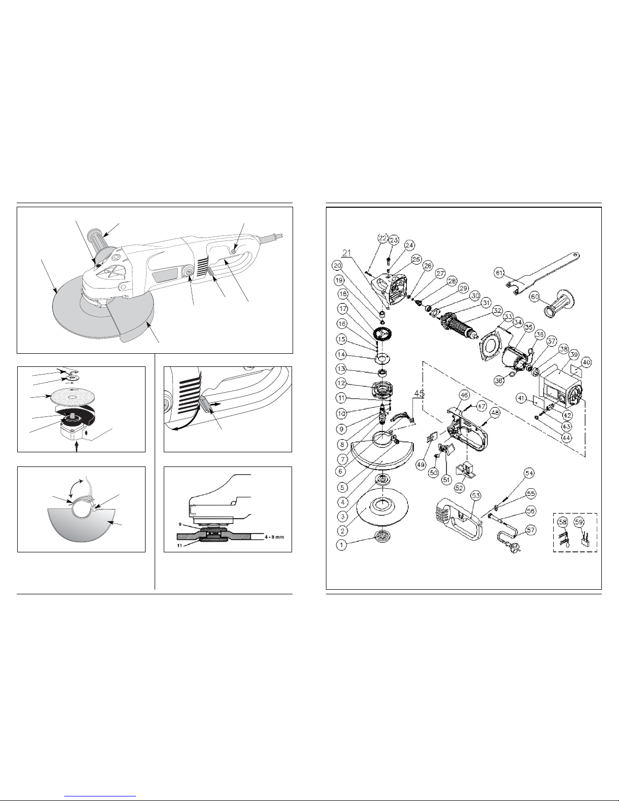
MOUNTING A GRINDING DISC.
Fig 2
Use grinding discs of the correct dimension. Use fibre
reinforced grinding discs only. The grinding disc must
not touch the edge of the guard.
• Press the spindle lock (3) and turn the spindle (10)
until it engages in the lock. Keep the spindle lock
pressed during this procedure.
• Remove the flange nut (11) from the spindle using the
spanner (12).
• Position the grinding disc (4) on the flange (9).
• Place the flange nut on the spindle an tighten it using
the spanner.
• Release the spindle lock and check that the spindle is
unlocked by rotating it.
MOUNTING THE PROTECTIVE GUARD
Fig. 2+3
Tool-les protective guard
The protective guard is pre-adjusted for the diameter of
the spindle shaft. If necessary, the tension of the clamping
lever can be adjusted by turning the adjustment-bolt
(13). Pay attention to the correct fitting of the guard (7)
on the spindle shaft (10).
• Open the clamping lever (14)
• Place the protective guard across the spindle shaft on
the machine head in the required position
• Close the clamping lever (14) to clamp the
protective guard (7).
Warning: the closed side of the protective guard has to
point towards the user.
ROTATING THE HANDGRIP
Fig. 4
The handgrip can be rotaded 90oregard to the machine
housing. This can result in a better control of the On/Off
switch during special working positions; for example for
grinding or left-hand users.
• Pull the knob (8) backwards with thumb and
forefinger.
• Rotate the handgrip in the new position (until the
blocking).
MOUNTING THE SIDE HANDLE
Fig 1
The side handle can be used for both left-hand and right-
hand control.
• Fasten the side handle (Fig. 5) for left-hand operation
on the right-hand side of the machine.
• Fasten the side handle for right-hand operation on
the left-hand side of the machine.
• Fasten the side handle for upright working at the top
of the machine.
Make sure that the side handle is fastened
properly and cannot loosen unexpectedly.
MOUNTING GRINDING DISCS AND
ROUGHING DISCS
Fig. 3 and 4 show how to mount the flange (11) when
using thick (4 – 8 mm) and thin (2,5 – 4 mm) discs.
4. USE
SPECIAL ATTENTION WHEN STARTING
THE MACHINE
• Clamp the workpiece and make sure that the
workpiece cannot slide from under the machine
during the cutting activities.
• When working with the machine, always hold it
firmly with both hands and provide for a secure
stance.
• Always direct the cable to the rear away from the
machine.
• Insert the mains plug only when the machine is
switched off.
• Apply the machine to the workpiece only when
switched on
Never use the machine for grinding magnesium
workpieces.
SWITCHING ON AND OFF
• This machine is equipped with a safety switch.
• Start the machine by pressing the “lock off” button
(to disengrage the switch) and switch on the
machine.
Before start working, the machine must be run
according to the max. speed.
OPERATION
• Hold the machine firmly and move it against the
workpiece. Move the grinding disc evenly across the
workpiece.
• Move the machine during roughing under an angle of
30º - 40º across the workpiece (fig. 7).
Never use grinding discs for roughing!
• The machine must always work opposite to the
direction of rotation. Therefore, never move the
machine in the other direction! Otherwise, the
danger exists of it being pushed uncontrolled out of
the cut (fig. 8).
• Inspect the grinding disc regularly. Worn discs have a
negative effect on efficiency of the machine. Replace
the grinding disc on time.
• Do not put the machine down when the motor is still
running. Do not place the machine on a dusty
6Powercraft
Table of contents
Other Power Craft Grinder manuals

Power Craft
Power Craft PSM-200 User manual

Power Craft
Power Craft 69162 User manual

Power Craft
Power Craft S1J-135A User manual

Power Craft
Power Craft PAG-115/1020 Technical manual

Power Craft
Power Craft 69157 User manual

Power Craft
Power Craft 11940 User manual

Power Craft
Power Craft 11942 User manual

Power Craft
Power Craft 1020W Technical manual

Power Craft
Power Craft 80036 User manual

Power Craft
Power Craft PAG-230/2100 Technical manual