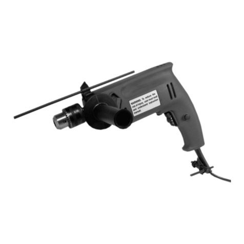
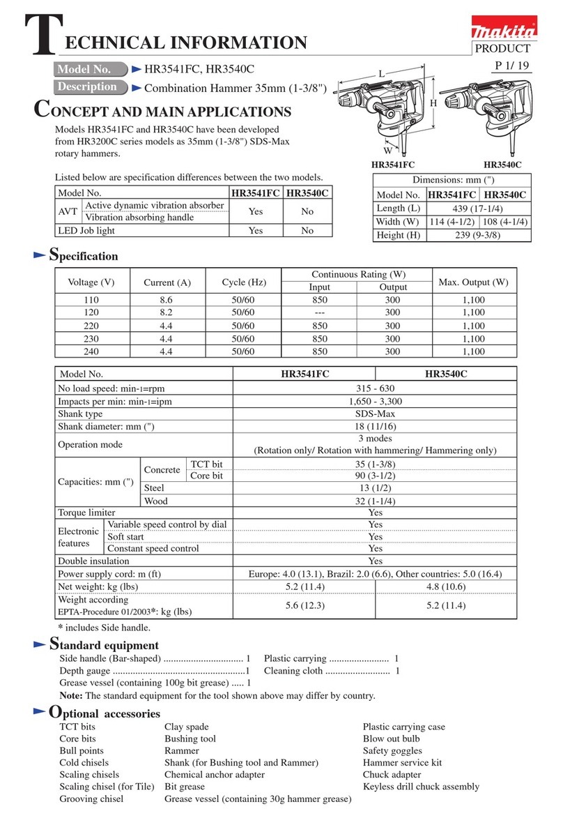
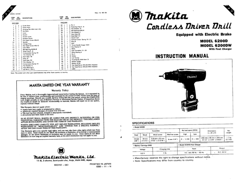
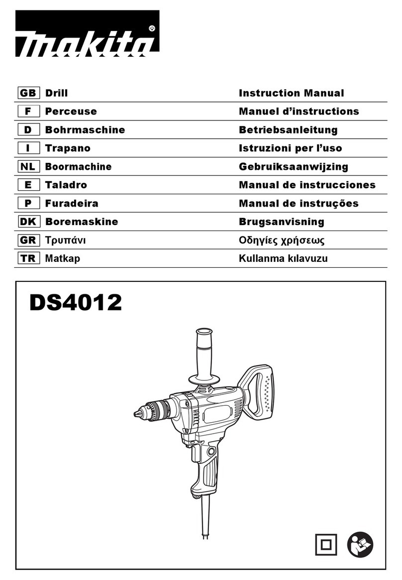
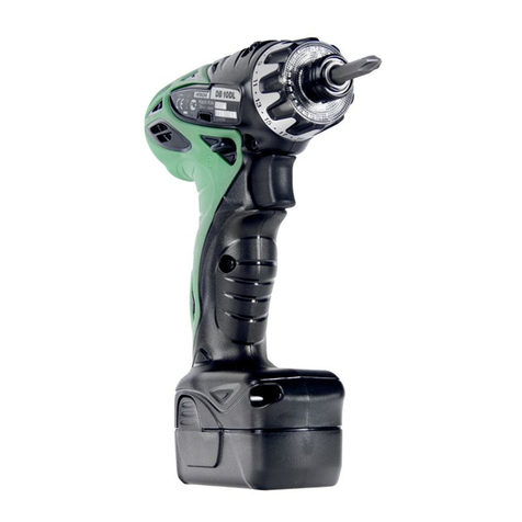
Power Fist 8416331 User manual

User Manual
8416331V 2.0
1/2 in. Hammer Drill
Please read and understand all instructions before use.
Retain this manual for future reference.


3
For technical questions call: 1-800-665-8685
V 2.0 8416331
1/2 in. Hammer Drill
SPECIFICATIONS
Voltage Rating 120 V, 60 Hz AC
Amperes 6.3 Amp
No Load Speed 2,800 RPM
Chuck 1/2 in. Keyed
Maximum Drilling Capacity in Metal 3/8 in. (10 mm)
Impact rate 0 to 44,800 BPM
SAFETY
IMPORTANT SAFETY PRECAUTIONS
WARNING! The warnings, cautions and instructions discussed in this instruction manual cannot cover all
possible conditions and situations that may occur. It must be understood by the operator that common sense
and caution are factors which cannot be built into this product, but must be supplied by the operator.
WARNING! Read and understand all instructions before using this tool. Keep this manual for the safety warnings
and precautions, operating, inspection and maintenance instructions. When using this tool, basic precautions
should always be followed to reduce the risk of personal injury and/or damage to the equipment. Note that when
this manual refers to a part number, it refers to the parts list included. Before allowing someone else to use this
tool, make sure they are aware of all safety information.
WORK AREA
1. Keep your work area clean and well lit. Cluttered and dark areas invite accidents.
2. Operate in a safe work environment. Do not use machines or tools in damp or wet locations. Do not expose
to rain. Do not use power tools in the presence of flammable gases or liquids.
3. Keep children, bystanders and visitors away from the work area. Do not let them handle tools or extension
cords. No one should be in the work area if they are not wearing suitable protective equipment.
4. Do not operate power tools in explosive atmospheres, such as in the presence of flammable liquids, gases or
dust. Power tools create sparks which may ignite the dust or fumes.
5. Store unused equipment. When not in use, tools must be stored in a dry location to prevent rust. Always
lock up tools and keep them out of reach of children
Safety Icons
Wear suitable
eye protection.
Use of protective gloves is
recommended. Double insulated.

1/2 in. Hammer Drill
4For technical questions call: 1-800-665-8685
8416331V 2.0
PERSONAL SAFETY
1. Dress properly, wear protective equipment. Use breathing, ear, eye, face, foot, hand and head protection.
Always wear ANSI approved impact safety goggles, which must provide both frontal and side protection.
Protect your hands with suitable gloves. Wear a full face shield if your work creates metal filings or wood
chips. Protect your head from falling objects by wearing a hard hat. Wear an ANSI approved dust mask or
respirator when working around metal, wood and chemical dusts and mists. Wear ANSI approved earplugs.
Protective, electrically non-conductive clothes and non-skid footwear are recommended when working. Wear
steel toed boots to prevent injury from falling objects.
2. Do not over reach; keep proper footing and balance at all times. Proper footing and balance enables better
control of the tool in unexpected situations.
3. Keep any articles of clothing, jewelry, hair etc. away from moving parts. These can be caught in moving
parts, resulting in damage to the tool and/or serious injury.
4. Stay alert, watch what you are doing and use your common sense. Do not operate any machine or tool when
you are tired, under the influence of drugs, alcohol or medications.
5. Use clamps or other practical ways to secure and support the work piece to a stable platform. Holding the
work piece by hand or against your body is unstable and may lead to loss of control.
6. Prevent unintentional starting. Ensure the switch is in the off-position before connecting to power source
and/or battery pack, picking up or carrying the tool. Carrying power tools with your finger on the switch or
energising power tools that have the switch on invites accidents.
ELECTRICAL SAFETY
1. Disconnect power supply. Disconnect from power supply when not in use, before cleaning, servicing or
changing any parts or accessories.
2. Protect yourself against electric shocks when working on electrical equipment. Avoid body contact with
grounded surfaces such as pipes, radiators, cooking stoves and refrigerators. There is an increased chance
of electrical shock if your body is grounded.
3. Use caution when performing an operation where the fastener may contact hidden wiring or its own cord.
Fasteners contacting a “live” wire may make exposed metal parts of the power tool “live” and could give the
operator an electrical shock.
4. Double insulated tools are equipped with a polarized plug (one blade is wider than the other). This plug will
fit in a polarized outlet only one way. If the plug does not fit fully in the outlet, reverse the plug. If it still does
not fit, contact a qualified electrician to install a polarized outlet. Do not change the plug in any way. Double
insulation eliminates the need for a three wire grounded power cord and grounded power supply system.
5. Grounded tools must be plugged into an outlet properly installed and grounded in accordance with all codes
and ordinances. Never remove the grounding prong or modify the plug in any way. Do not use any adapter
plugs. Check with a qualified electrician if you are in doubt as to whether the outlet is properly grounded. If
the tool should electronically malfunction or break down, grounding provides a low resistance path to carry
electricity away from the user.
6. Do not abuse the cord. Never use the cord to carry the tools or pull the plug from an outlet. Keep cord away
from heat, oil, sharp edges or moving parts. Do not operate this tool if the power cord is frayed or damaged.
Replace damaged cords immediately. Damaged cords increase the risk of electric shock. Do not modify the
plug in any way.
7. When operating a power tool outside, use an outdoor extension cord marked “W-A” or “W”. These cords are
rated for outdoor use and reduce the risk of electric shock. Use in conjunction with a Ground Fault Circuit
Interrupter (GFCI). If operating a power tool in a damp location is unavoidable, the use of a GFCI reduces the
risk of electric shock. It is recommended that the GFCI should have a rated residual current of 30 mA or less.
8. Avoid using an unnecessarily long extension cord. Choose a cord that is appropriate for the situation, as a
cord that is too long and running across the floor can be more dangerous than helpful. Using a cord that is
too long or too thin could damage the tool. Unroll the cord completely to prevent it from overheating.
9. Place the electrical cord in a position that prevents it from coming into contact with the tool and from getting
caught by the work piece. The cord should always stay behind the tool.

1/2 in. Hammer Drill
5
For technical questions call: 1-800-665-8685
8416331 V 2.0
EXTENSION CORD PRECAUTIONS
WARNING! Keep the extension cord clear of the working area.
• Position the cord so it will not get caught on the workpiece, tools or any other obstructions while you are
working with the power tool.
• Make sure any extension cord used with this tool is in good condition. When using an extension cord, be
sure to use one of heavy enough gauge to carry the current the tool will draw. An undersized cord will cause
a drop in line voltage resulting in loss of power and overheating.
• The table bellow shows the correct size to use according to cord length and nameplate ampere rating. If in
doubt, use the next heavier gauge. The smaller the gauge number the heavier the cord.
MINIMUM GAUGE (AWG)
EXTENSION CORDS (120 V use only)
Amperage rating Total length
More than Less than 25 ft (7.5 m) 50 ft (15 m) 100 ft (30 m) 150 ft (45 m)
0 6 18 16 16 14
6 10 18 16 14 12
10 12 16 16 14 12
12 16 14 12 Not Applicable
• Be sure your extension cord is properly wired and in good condition. Always replace a damaged extension
cord or have it repaired by a qualified electrician before using it. Protect your extension cord from sharp
objects, excessive heat and damp or wet areas.
• Use a separate electrical circuit for your power tools. This circuit must not be less than 14 gauge wire and
should be protected with either a 15 A time delayed fuse or circuit breaker. Before connecting the power
tool to the power source, make sure the switch is in the OFF position and the power source is the same as
indicated on the nameplate. Running at lower voltage will damage the motor.
SPECIFIC SAFETY PRECAUTIONS
WARNING! Know your impact drill. Read the Owner’s Manual carefully. Learn the tool’s applications and
limitations, as well as the specific potential hazards related to this tool. Following this rule will reduce the risk
of electric shock, fire or serious injury.
WARNING! Never use the drill in “impact” mode unless a proper masonry bit is installed and you
are drilling in concrete.
WARNING! Always use a safety shield, hearing protection and a dust mask when operating the drill
in “impact” mode.
• Do not drill material too small to be securely held.
• Always keep hands out of the path of the drill bit. Avoid awkward hand positions where a sudden slip could
cause your hand to move into the path of the drill bit.
• Make sure there are no nails or foreign objects in the part of the workpiece to be drilled.
• Do not install or use any drill bit that exceeds 7 in. (175 mm) in length or extends more than 6 in. (150 mm)
beyond the chuck jaws. They can suddenly bend or break.
• Before starting the operation, jog the drill switch to make sure the drill bit does not wobble or vibrate.
• Do not use fly cutters or multiple-part hole cutters, as they can come apart or become unbalanced in use.
• Make sure the spindle has come to a complete stop before touching the chuck or attempting to change the
drill bit.
• Always make sure the chuck is tight and the drill bit is firmly tightened in the chuck before starting the drill.

1/2 in. Hammer Drill
6For technical questions call: 1-800-665-8685
8416331V 2.0
TOOL USE AND CARE
1. Use the right tool for the job. Do not attempt to force a small tool or attachment to do the work of a larger
industrial tool. The tool will perform better and more safely at the task for which it was intended. Do not
modify this tool or use for a purpose for which it was not designed.
2. Securely hold this tool using both hands. Using tools with only one hand can result in loss of control.
3. Maintain tools with care. Keep tools clean, and in good condition for a better and safer performance. Follow
instructions for lubricating and changing accessories. Inspect tool fittings, alignment periodically and, if
damaged, have them repaired by an authorized technician or replaced. The handles must be kept clean, dry
and free from oil and grease at all times. A properly maintained tool reduces the risk of binding and is easier
to control. Applying excessive force can lead to slips and damage to your work or personal injury.
4. Remove adjusting keys and wrenches. Check that keys and adjusting wrenches are removed from the tool or
machine before connecting it. A wrench or key that is left attached to a rotating part of the tool increases the
risk of personal injury.
5. Avoid unintentional starts. Be sure that the switch is in neutral or OFF position when not in use and before
connecting it to any power source. Do not carry the tool with fingers near or on the switch.
6. Only use the lubricants supplied with the tool or specified by the manufacturer. Other lubricants may not be
suitable and may damage the tool or even make the tool explode.
7. When not in use for an extended period, apply a thin coat of lubricant to the steel parts to avoid rust.
8. Maintain the label and name plate on the tool. These carry important information. If unreadable or missing,
contact Princess Auto for a replacement.
LUBRICATION
All of the bearings in this tool are lubricated with a sufficient amount of high-grade lubricant for the life of the unit
under normal conditions. Therefore, no further lubrication is required.
WARNING! NEVER use WD-40 to clean or lubricate your tool. WD-40 is a solvent that will break down the
internal grease and cause the tool to seize up.
UNPACKING
1. Carefully remove the parts and accessories from the box.
2. Make sure that all items listed in the parts lists are included.
3. Inspect the parts carefully to make sure the tool was not damaged while shipping.
4. Do not discard the packaging material until you have carefully inspected and satisfactorily operated the tool.
WARNING! If any part is missing, do not operate the tool until the missing parts are replaced. Failure to do so
could result in serious personal injury.

1/2 in. Hammer Drill
7
For technical questions call: 1-800-665-8685
8416331 V 2.0
KNOW YOUR IMPACT DRILL
INSPECTION
WARNING! Use only accessories recommended for this drill. Follow instructions that accompany accessories.
Use of improper accessories may cause injury to the operator or damage to the drill.
WARNING! If any part is missing or damaged, do not plug the tool into the power source until the missing or
damaged part is replaced.
PARTS IDENTIFICATION
DRILL COMPONENTS
Key Description Qty
A Drill 1
B Chuck Key 1
C Auxiliary Handle 1
D Auxiliary Handle Collar 1
E Depth Rod 1

1/2 in. Hammer Drill
8For technical questions call: 1-800-665-8685
8416331V 2.0
FORWARD / REVERSE SWITCH
The forward / reverse switch (1) is conveniently mounted above the trigger switch
(See Figure 1). To make the drill rotate clockwise for drilling or driving screws, push the
forward / reverse switch to the left. To make the drill rotate counter clockwise for removing
screws, push the forward / reverse switch to the right.
NOTES:
• Never change position of the forward / reverse switch while the chuck is turning.
• The trigger switch will NOT function with the forward / reverse switch in the middle position.
VARIABLE SPEED TRIGGER SWITCH
This drill is equipped with a variable speed ON / OFF switch.
1. Turning the dial clockwise increases the speed of the hammer drill (2) (See Figure 2).
NOTE: Drill will turn at its slowest speed when the dial switch is turned counter clockwise.
2. To stop the drill, release the trigger switch.
NOTE: Drilling at a slow drilling speed for an extended period of time may cause
the drill motor to overheat. If the drill gets hot, stop drilling and allow it to cool
for at least 15 minutes.
TRIGGER SWITCH LOCK
The trigger switch lock-on feature allows the trigger switch to be locked in the ON position
at full speed when continuous operation for extended periods of time is required (See Figure 3).
To lock the trigger switch in the ON position, pull back on the trigger switch to start the drill
and push the trigger switch lock button (3) into the drill handle. Release the trigger switch
while holding the trigger switch lock button into the drill handle. The drill will continue to run.
To release the trigger switch lock button, pull the trigger switch back and then release the trigger.
DRILL / IMPACT SWITCH
The drill / impact switch (4) changes the drilling mode between conventional
drilling and impact for drilling concrete (See Figure 4). To operate the drill in drill mode,
push the drill / impact switch to the right. To operate the drill in impact mode,
push the drill / impact switch to the left.
WARNING! Always use carbide tipped masonry bits when drilling in masonry.
Any other type of bit could break and possibly cause serious injury.
INSTALLING THE AUXILIARY HANDLE
Install the auxiliary handle for two handed operation of the drill (See Figure 5).
This is particularly important for impact drilling in concrete.
1. Turn the auxiliary handle (1) counter clockwise to open the mounting collar (2).
2. Slide the auxiliary handle collar over the chuck and fully onto the drill housing (3).
3. Rotate the auxiliary handle to a comfortable position.
NOTE: The auxiliary handle must be horizontal when using the depth rod.
4. Turn the auxiliary handle clockwise to tighten the mounting collar onto the drill housing.
NOTE: Do not over tighten the auxiliary handle or you will break the mounting collar.
Figure 1
Figure 2
Figure 3
Figure 4
Figure 5

1/2 in. Hammer Drill
9
For technical questions call: 1-800-665-8685
8416331 V 2.0
INSTALLING THE DEPTH ROD
The dept rod is used as a gauge to control the depth of the drilled hole.
1. Turn the auxiliary handle (1) counter clockwise to open the mounting collar (2)
(See Figure 6).
2. Insert the hexagonal end of the depth rod (3) into the matching hole in the auxiliary
handle mounting collar (4).
3. Position the depth rod so the tip of the round end (5) will contact the workpiece when
the drill reaches the appropriate depth.
NOTE: Auxiliary handle must be placed in the horizontal position to allow depth rod to
be inserted into the mounting collar. Tighten the auxiliary handle.
INSTALLING BITS
WARNING! Never hold the chuck body with one hand and use the drill power to rotate the
drill body to loosen or tighten bits. You may severely injure your hand.
1. Removed the drill plug from the power source.
2. Rotate the chuck collar (1) to open or close the jaws (2) to a point where the opening
is slightly larger than the bit size you intend to sue (See Figure 7). Raise the front
of your drill slightly to prevent the bit from falling out of the chuck jaws.
3. Insert the drill bit into the chuck the full length of the jaws.
4. Insert the chuck key (3) into one of the three holes in the chuck body. Rotate the chuck
key
clockwise until the drill bit is held firmly in place by the chuck jaws.
NOTE: Do not use a wrench on the chuck key or you may damage the key or chuck.
WARNING! Do not insert the drill bit into the chuck and tighten as shown in Figure 8.
The drill bit MUST be properly inserted with all three chuck jaws holding the bit centered
in the chuck. Failure to properly insert the drill bit could cause the drill bit to be thrown
from the chuck resulting in possible serious injury or damage to the chuck.
REMOVING BITS
1. Remove the drill plug from the power source.
2. Insert the chuck key into one of the three holes in the chuck body. Rotate chuck key
counter clockwise until the chuck jaws release the drill bit.
NOTE: Do not use a wrench on the chuck key or you may damage the key or the chuck.
3. Remove the drill bit.
Figure 6
Figure 7
Figure 8

1/2 in. Hammer Drill
10 For technical questions call: 1-800-665-8685
8416331V 2.0
DRILLING
WARNING! Every time you use the drill you should verify the following:
1. The chuck is tight.
2. The workpiece is properly secured.
3. Safety glasses are being worn.
• Failure to adhere to these safety rules can greatly increase the chances of injury.
• When drilling smooth hard surfaces such as metal, use a centre punch to mark the
desired hole location. This will prevent the drill bit from slipping off centre as
the hole is started.
NOTE: Use slower drilling speeds when drilling larger holes.
NOTE: Use a masonry bit with the drill in impact mode ONLY when drilling in concrete.
• The workpiece to be drilled should be secured in a vise or with clamps to keep it from
turning as the drill bit rotates (See Figure 9).
4. Check the drill bit to make sure it is firmly locked into the drill chuck and the forward / reverse switch is in
the forward position.
5. Hold the drill firmly with both hands whenever possible. Use one hand to grasp the handle and switch and
the other to grasp the body of the drill.
NOTE: Make sure the hand placed on the body of the drill does not cover the air vents. Covering these air
vents will reduce the motor cooling and possibly lead to overheating the motor.
6. While holding the drill firmly, place the point of the drill bit at the point to be drilled. Depress the trigger
switch to start the drill.
7. Move the drill bit into the workpiece applying only enough pressure to keep the bit cutting. Do not force the
drill bit or apply sideways pressure to elongate the hole.
WARNING! Be prepared for binding and bit breakthrough. When these situations occur, the drill bit has the
tendency to grab the workpiece. This action will kick the drill opposite to the direction of the drill bit’s rotation
and could cause a loss of control when breaking through the material as you complete drilling the hole. If you
are not prepared, this loss of control can result in possible serious injury.
When drilling metals, use a light oil on the drill bit to keep it from overheating. The oil will prolong the life of the drill
bit and improve the drill cutting action. If the bit jams in the workpiece or if the drill stalls, release the trigger switch
immediately. Remove the bit from the workpiece and determine the reason for the jam.
DRILLING IN CONCRETE
WARNING! Always use a face shield when drilling in concrete.
Always use the impact mode and slower drill speeds for faster drilling in concrete.
Always use carbide tipped masonry bits.
Figure 9

1/2 in. Hammer Drill
11
For technical questions call: 1-800-665-8685
8416331 V 2.0
CHUCK REMOVAL
The drill chuck must be removed in order to use some accessories.
To remove the chuck:
1. Unplug the drill from the power source.
2. Insert a 5/16 in. or larger hex hey (1) into the chuck (2) and tighten the
chuck jaws securely. Make sure each of the three chuck jaws (3) are
seated on a flat surface of the hex key (See Figure 10).
3. Tap the hex key sharply with a mallet (4) in a clockwise direction. This
action will loosen the screw in the chuck for easy removal.
4. Open the chuck jaws and remove the hex key.
5. Open the chuck jaws as far as possible using the chuck key.
6. Remove the chuck screw using a #2 Philips® screwdriver (See Figure 11).
NOTE: Turn the screw CLOCKWISE to remove it. This screw has a
left hand thread.
7. Insert the hex key into the chuck and tighten the jaws of the chuck
securely (See Figure 12). Tap the hex key sharply with a mallet in a
COUNTER CLOCKWISE direction. This will loosen the chuck on the
spindle. The chuck can now be unscrewed and removed from the spindle
by hand.
RETIGHTENING LOOSE CHUCK
After installing the chuck once it has been removed, the chuck may become loose
on the spindle and develop a wobble. Also, the chuck screw may become loose
Figure 10
Figure 11
Figure 12
causing the chuck jaws to bind and prevent them from closing. To tighten the chuck,
follow these steps:
1. Insert the hex key into the chuck and tighten the chuck securely.
2. Tap the hex key sharply with a mallet in a CLOCKWISE direction (See Figure 10).
This will tighten the chuck on the spindle.
3. Open the chuck jaws and remove the hex key.
4. Tight the chuck screw using a #2 Philips® screwdriver.
NOTE: Turn the screw COUNTER CLOCKWISE to tighten it. This screw has a left hand thread.
MAINTENANCE
WARNING! When servicing, use only identical replacement parts. Use of any other part may create a hazard or
cause product damage.
• DO NOT use solvents when cleaning the plastic parts. Plastics are susceptible to damage from
various types of commercial solvents and may be damaged by their use. Use a clean cloth to remove dirt,
dust, oil, grease etc.
• WARNING! Do not at any time allow brake fluids, gasoline, petroleum-based products, penetrating oils,
etc. to come into contact with plastic parts. They contain chemicals that can damage, weaken
or destroy the plastic.
• WARNING! To avoid fire or toxic reaction, never use gasoline, naphtha, and acetone, lacquer thinner or
similar highly volatile solvents to clean the tool.
• DO NOT abuse power tools. Abusive practices can damage the tool as well as the workpiece.
• WARNING! DO NOT attempt to modify tools or create accessories. Any such alteration or modification
is misuse and could result in a hazardous condition leading to possible serious injury.

1/2 in. Hammer Drill
12 For technical questions call: 1-800-665-8685
8416331V 2.0
DISPOSING OF THE TOOL
If your tool has become damaged beyond repair, do not throw it out. Bring it to the appropriate recycling facility.
PARTS BREAKDOWN
No. Description Qty
1 Screw 1
2 Chuck 1
3 Shaft 1
4 Impact Spring 1
5 Bearing 6002LB 1
6 Retaining Ring 1
7 Big Gear 1
8 Impact Ball 1
9 Impact Disc 1
10 Needle Bearing 1
11 Pin 2
12 Conversion Button 1
13 Leaf Spring 1
14 Bearing Seat 1
15 Bearing 608 1
16 Fan 1
No. Description Qty
17 Rotor 1
18 Left Housing 1
19 Brush Holder Support 2
20 Brush Holder 2
21 Carbon Brush 2
22 Bearing 607 1
23 Stator 1
24 Chuck Key 1
25 Switch 1
26 Cord Clamp 1
27 Tapping Screw 2
28 Cord Guard 1
29 AC Cord and Plug 1
30 Right Housing 1
31 Tapping Screw 9

Manuel du Propriétaire
8416331V 2.0
Perceuse à
percussion de 1/2 po
Vous devez lire et comprendre toutes les instructions avant d'utiliser l'appareil.
Conservez ce manuel afin de pouvoir le consulter plus tard.

2
Si vous avez des questions de nature technique, veuillez appeler le 1-800-665-8685
8416331V 2.0
Perceuse à
percussion de 1/2 po
SPÉCIFICATIONS
Tension nominale 120 V, 60 Hz c.a.
Ampères 6,3 A
Vitesse à vide 2 800 TPM
Mandrin Clé de 1/2 po
Capacité max. de perçage dans le métal 10 mm (3/8 po)
Vitesse d'impacte 0 à 44 800 coups/min
SÉCURITÉ
CONSIGNES DE SÉCURITÉ IMPORTANTES
AVERTISSEMENT ! Les avertissements, les attentions et les instructions mentionnés dans ce manuel
d’instructions ne peuvent pas couvrir toutes les conditions et situations pouvant se produire. L’opérateur doit
comprendre qu’il doit faire preuve de bon sens et prendre les précautions nécessaires pour assurer sa sécurité
lors de l’utilisation de l’outil.
AVERTISSEMENT ! Veuillez lire et comprendre toutes les instructions avant d’utiliser cet outil. Conservez
ce manuel qui contient les avertissements et les mesures de sécurité, les instructions de fonctionnement,
d’inspection et d’entretien. Lorsque vous utilisez cet outil, vous devez toujours prendre les précautions de base
pour réduire le risque de blessure et de dommage à l’équipement. Veuillez noter que lorsque ce manuel fait
référence à un numéro de pièce, il fait référence à la liste des pièces comprise. Avant de permettre à un autre
individu d’utiliser cet outil, assurez-vous qu’il connaît toutes les consignes de sécurité.
Symboles de sécurité
Porter un dispositif adéquat
de protection des yeux.
Le port de gants de sécurité
est recommandé. Isolation double.

Perceuse à percussion de 1/2 po
3
Si vous avez des questions de nature technique, veuillez appeler le 1-800-665-8685
8416331 V 2.0
AIRE DE TRAVAIL
1. Gardez votre aire de travail propre et bien éclairée. Les endroits encombrés et sombres sont une invitation
aux accidents.
2. Travaillez dans un environnement de travail sécuritaire. N’utilisez pas les appareils ou les outils dans des
endroits humides ou mouillés. Gardez les outils à l’abri de la pluie. N’utilisez pas d’outils électriques en
présence de gaz ou de liquides inflammables.
3. Gardez les enfants, les spectateurs et les visiteurs à l’écart de l’aire de travail. Ne les laissez pas manier les
outils ni les rallonges de câble. Aucune personne ne doit se trouver dans l’aire de travail à moins de porter
l’équipement de protection approprié.
4. N’utilisez pas d’outils électriques dans des environnements explosifs tels qu’en présence de liquides
inflammables, de gaz ou de poussière. Les outils électriques créent des étincelles qui peuvent enflammer la
poussière ou les vapeurs.
5. Entreposez l’équipement non utilisé. Lorsqu’ils ne sont pas en usage, les outils doivent être entreposés dans
un endroit sec pour prévenir la rouille. Gardez toujours les outils dans un endroit verrouillé et hors de la
portée des enfants.
SÉCURITÉ PERSONNELLE
1. Portez des vêtements appropriés et de l’équipement de protection. Utilisez des protections pour les voies
respiratoires, les oreilles, les yeux, le visage, les pieds, les mains et la tête. Portez toujours des lunettes
de sécurité étanches approuvées par l’ANSI qui offrent une protection frontale et latérale. Protégez-vous
les mains à l’aide de gants appropriés. Portez un écran facial panoramique si votre travail produit des
limailles ou des copeaux de bois. Protégez-vous la tête de la chute d’objets en portant un casque de
protection. Portez un masque antipoussières ou un appareil respiratoire approuvés par l’ANSI lorsque vous
travaillez près du métal, du bois ou des poussières et vapeurs chimiques. Portez des bouchons d’oreille
approuvés par l’ANSI. Des vêtements de protection non conducteurs et des chaussures antidérapantes sont
recommandés pour le travail. Pour éviter les blessures dues aux chutes d’objets, portez des chaussures à
embout d’acier.
2. Ne vous étirez pas trop loin; restez stable et en équilibre en tout temps. Une stabilité et un équilibre
appropriés permettent d’avoir un meilleur contrôle de l’outil en cas de situations inattendues.
3. Tenez les vêtements, les bijoux, les cheveux, etc. à l’écart des pièces mobiles. Ces derniers peuvent se
coincer dans les pièces mobiles et ainsi endommager l’outil ou provoquer de graves blessures.
4. Restez alerte, portez attention à vos gestes et faites preuve de bon sens. N’utilisez pas d’appareil ou d’outil si
vous êtes fatigué ou sous l’effet de drogues, d’alcool ou de médicaments.
5. Utilisez des serres ou un autre moyen pratique pour fixer et soutenir la pièce à travailler sur une plate-
forme stable. Une pièce à travailler tenue dans les mains ou appuyée contre le corps est instable et risque
d’entraîner une perte de contrôle.
6. Prévenez les mises en marche involontaires. Assurez-vous que l’interrupteur est à la position ARRÊT avant
de connecter l’outil à une source d’alimentation/au bloc-pile, de le soulever ou de le transporter. Le fait de
transporter un outil avec le doigt sur la gâchette ou de brancher un outil dont l’interrupteur est en position
de MARCHE peut mener à un accident.

Perceuse à percussion de 1/2 po
4Si vous avez des questions de nature technique, veuillez appeler le 1-800-665-8685
8416331V 2.0
SÉCURITÉ EN ÉLECTRICITÉ
1. Débranchez la source d’alimentation. Débranchez l’outil de la source d’alimentation lorsqu’il n’est pas utilisé
et avant le nettoyage, l’entretien ou le remplacement de pièces ou d’accessoires.
2. Protégez-vous contre les chocs électriques lorsque vous travaillez en présence d’équipement électrique.
Évitez un contact entre votre corps et les surfaces reliées à la terre comme les tuyaux, radiateurs, cuisinières
et réfrigérateurs. Il y a un risque plus élevé de choc électrique si votre corps est relié à la terre.
3. Faites attention lorsque vous effectuez une tâche au cours de laquelle la fixation peut entrer en contact avec
un câble caché ou son propre cordon. Les fixations qui entrent en contact avec un fil sous tension peuvent
mettre sous tension les parties métalliques exposées de l’outil électrique, ce qui pourrait donner un choc
électrique à l’opérateur.
4. Les outils à double isolation sont munis d’une fiche polarisée (une broche est plus large que l’autre).
Cette fiche s’insérera dans une prise polarisée dans une direction seulement. Si la fiche ne s’insère pas
complètement dans la prise, tournez-la. Si elle ne s’insère toujours pas, contactez un électricien qualifié
pour faire installer une prise polarisée. Ne modifiez la fiche d’aucune manière. La double isolation élimine le
besoin d’un cordon d’alimentation à trois fils mis à la terre et d’un système d’alimentation mis à la terre.
5. Les outils mis à la terre doivent être branchés dans une prise qui est correctement installée et mise à la terre
conformément à tous les codes et à tous les règlements. Ne retirez jamais la broche de masse et ne modifiez
jamais la fiche. N’utilisez aucune fiche d’adaptation. Consultez un électricien qualifié si vous doutez de la
mise à la terre appropriée d’une prise. En cas de défaillance électronique ou de bris de l’outil, la mise à la
terre procure un trajet de faible résistance pour éloigner l’électricité de l’utilisateur.
6. N’utilisez pas le cordon de manière abusive. Ne transportez jamais l’outil par le cordon et ne tirez jamais
sur celui-ci pour enlever la fiche de la prise. Tenez le cordon à l’écart de la chaleur, de l’huile, des rebords
coupants ou des pièces mobiles. N’utilisez pas cet outil si le cordon d’alimentation est effilé ou endommagé.
Remplacez les cordons endommagés immédiatement. Les cordons endommagés augmentent le risque de
choc électrique. Ne modifiez pas la fiche de quelque façon que ce soit.
7. Si vous utilisez un outil électrique à l’extérieur, utilisez une rallonge d’extérieur identifiée « W-A » ou « W ».
Ces rallonges sont nominales pour un usage extérieur et réduisent le risque de choc électrique. Utilisez avec
un disjoncteur de fuite de terre (GFCI). Si l’utilisation d’un outil électrique dans un lieu humide est inévitable,
l’usage d’un disjoncteur de fuite de terre réduit le risque de choc électrique. Il est recommandé que le
disjoncteur de fuite à la terre possède un courant résiduel nominal de 30 mA ou moins.
8. Évitez d’utiliser une rallonge excessivement longue. Choisissez une rallonge appropriée à la situation, car une
rallonge trop longue qui traîne sur le plancher peut être plus dangereuse qu’utile. L’usage d’une rallonge trop
longue ou trop mince peut endommager l’outil. Déroulez le cordon au complet pour éviter sa surchauffe.
9. Disposez le cordon électrique de façon qu’il ne touche pas l’outil et qu’il ne risque pas de se prendre dans la
pièce à travailler. Le cordon doit toujours se trouver derrière l’outil.
PRÉCAUTIONS CONCERNANT LA RALLONGE
AVERTISSEMENT ! Veillez à ce que la rallonge reste éloignée de l’aire de travail.
• Placez la rallonge de façon qu’elle ne soit pas coincée sur la pièce de travail, les outils ou toute autre
obstruction lorsque vous travaillez avec l’outil électrique.
• Assurez-vous que toute rallonge utilisée avec cet outil est en bon état. Lorsque vous utilisez une rallonge,
assurez-vous d’en utiliser une qui ait un calibre suffisant pour transporter le courant nécessaire pour
l’outil. Une rallonge d’un calibre insuffisant entraînera une chute de tension, une perte de puissance et une
surchauffe.
• Le tableau suivant indique le calibre correct à utiliser en fonction de la longueur du cordon et des
caractéristiques d’intensité figurant sur la plaque signalétique. En cas de doute, utilisez le calibre supérieur.
Plus le numéro du calibre est petit, plus le cordon est robuste.

Perceuse à percussion de 1/2 po
5
Si vous avez des questions de nature technique, veuillez appeler le 1-800-665-8685
8416331 V 2.0
CALIBRE MINIMUM (AWG)
RALLONGES (utilisation de 120 V uniquement)
Intensité nominale de courant
(ampères) Longueur totale
Plus de Moins de 7,5 m (25 pi) 15 m (50 pi) 30 m (100 pi) 45 m (150 pi)
0 6 18 16 16 14
6 10 18 16 14 12
10 12 16 16 14 12
12 16 14 12 Sans objet
• Assurez-vous que votre rallonge est câblée correctement et en bon état. Remplacez toujours une rallonge
endommagée ou faites-la réparer par un électricien qualifié avant de l’utiliser. Protégez votre rallonge contre
les objets tranchants, la chaleur excessive et les zones humides ou mouillées.
• Utilisez un circuit électrique séparé pour vos outils électriques. Ce circuit doit comporter du fil de calibre 14
au moins et doit être protégé par un fusible temporisé de 15 A ou un disjoncteur. Avant de brancher l’outil
électrique à la source d’alimentation, vérifiez que son interrupteur est à la position ARRÊT et que la source
d’alimentation est la même que celle indiquée sur la plaque signalétique. L’utilisation d’une tension inférieure
endommagera le moteur.
MESURES DE SÉCURITÉ SPÉCIFIQUES
AVERTISSEMENT ! Vous devez connaître votre perceuse à percussion. Lisez avec soin le Manuel du
propriétaire. Vous devez bien comprendre les applications et les limitations de l’outil, ainsi que les dangers
potentiels particuliers associés à cet outil. L’observation de cette règle réduira le risque de choc électrique,
d’incendie ou de blessure grave.
AVERTISSEMENT ! N’utilisez jamais la perceuse dans le mode de « percussion » si un embout de maçonnerie
approprié n’est pas installé et vous ne percez pas le béton.
AVERTISSEMENT ! Utilisez toujours un écran protecteur, une protection de l’ouïe et un masque antipoussières
lorsque vous faites marcher la perceuse dans le mode de « percussion ».
• Ne percez pas les matériaux trop petits pour être immobilisés en toute sécurité.
• Gardez toujours les mains hors de la trajectoire du foret. Évitez les positions de main maladroites pour
lesquelles un glissement soudain pourrait amener la main dans la trajectoire du foret.
• Assurez-vous que la partie de la pièce à travailler qui sera percée ne contient pas de clous ou
d’objets étrangers.
• N’installez pas et n’utilisez pas de foret dont la longueur excède 175 mm (7 po) ou qui dépasse la mordache
de plus de 150 mm (6 po). Ils peuvent se tordre ou casser subitement.
• Avant de commencer, actionner le commutateur de la perceuse pour vous assurer que le foret n’est pas sujet
à une rotation déséquilibrée ou des vibrations.
• N’utilisez pas de coupe-joints ou de scies emporte-pièce en plusieurs parties car ils peuvent se disloquer ou
devenir déséquilibrés pendant l’utilisation.
• Assurez-vous que la broche s’est complètement arrêtée avant de toucher le mandrin ou d’essayer de
changer le foret.
• Assurez-vous toujours que le mandrin est serré et que le foret est fermement serré dans le mandrin avant de
mettre en marche la perceuse.

Perceuse à percussion de 1/2 po
6Si vous avez des questions de nature technique, veuillez appeler le 1-800-665-8685
8416331V 2.0
UTILISATION ET ENTRETIEN DE L’OUTIL
1. Utilisez le bon outil pour effectuer le travail. N’utilisez pas de petit outil ou de petit accessoire pour effectuer
le travail d’un outil industriel plus gros. L’outil offrira une performance et une sécurité supérieures s’il
est utilisé pour une tâche à laquelle il est destiné. Ne modifiez pas cet outil et ne l’utilisez pas à des fins
auxquelles il n’a pas été conçu.
2. Tenez cet outil solidement des deux mains. L’utilisation de l’outil avec une seule main peut causer une perte
de contrôle.
3. Entretenez les outils avec soin. Gardez les outils propres et en bon état pour obtenir une performance
supérieure et plus sécuritaire. Suivez les instructions pour lubrifier et remplacer les accessoires. Vérifiez
périodiquement les raccords et l’alignement de l’outil et, en cas de dommage, demandez à un technicien
autorisé de les réparer ou les remplacer. Les poignées doivent demeurer propres, sèches et exemptes d’huile
et de graisse en tout temps. Un outil bien entretenu réduira les risques de coincement et sera plus facile à
maîtriser. L’utilisation d’une force excessive peut causer des glissements et endommager votre travail ou
causer des blessures.
4. Enlevez les clavettes et les clés de réglage. Vérifiez si les clavettes et les clés de réglage ont été retirées
de l’outil ou de l’appareil avant de le brancher. Une clé ou clavette laissée en place sur une pièce rotative
augmente le risque de blessure.
5. Évitez les mises en marche involontaires. Assurez-vous que le commutateur est en position neutre ou
ARRÊT lorsque l’outil n’est pas utilisé et avant de le brancher à une source d’alimentation. Ne transportez
pas l’outil les doigts sur le commutateur ou à proximité de celui-ci.
6. Utilisez seulement les lubrifiants fournis avec l’outil ou spécifiés par le fabricant. Les autres lubrifiants
peuvent ne pas convenir et endommager l’outil ou même causer son explosion.
7. Si l’outil n’est pas utilisé pendant une période prolongée, appliquez une mince couche de lubrifiant sur les
pièces en acier pour éviter la rouille.
8. Veillez à maintenir intactes l’étiquette et la plaque signalétique de l’outil. Elles comportent des
renseignements importants. Si elles sont illisibles ou manquantes, communiquez avec Princess Auto pour
les remplacer.
LUBRIFICATION
Tous les roulements de cet outil sont lubrifiés d’une quantité suffisante de lubrifiant de haute qualité pour la toute la
durée de service de l’outil, en conditions normales d’utilisation. Par conséquent, aucune autre lubrification
n’est requise.
AVERTISSEMENT ! N’utilisez JAMAIS de WD-40 pour nettoyer ou lubrifier votre outil. Le WD-40 est un solvant
qui provoque la décomposition de la graisse interne et, par conséquent, le grippage de votre outil.
DÉBALLAGE
1. Retirez soigneusement les pièces et les accessoires de la boîte.
2. Assurez-vous que tous les articles figurant sur les listes de pièces sont compris.
3. Inspectez les pièces attentivement pour vous assurer que l’outil n’a pas été endommagé pendant
son transport.
4. Ne jetez pas le matériel d’emballage avant d’avoir examiné attentivement l’outil et de l’avoir fait fonctionner
avec succès.
AVERTISSEMENT ! Si des pièces sont manquantes, ne faites pas fonctionner l’outil avant que les pièces
manquantes ne soient remplacées. Le non-respect de cet avertissement peut entraîner de graves blessures.

Perceuse à percussion de 1/2 po
7
Si vous avez des questions de nature technique, veuillez appeler le 1-800-665-8685
8416331 V 2.0
UTILISATION
CONNAÎTRE VOTRE PERCEUSE À PERCUSSION
INSPECTION
AVERTISSEMENT ! Utilisez seulement les accessoires recommandés pour cette perceuse. Suivez les
instructions fournies avec les accessoires. L’utilisation d’accessoires inappropriés peut blesser l’opérateur ou
endommager la perceuse.
AVERTISSEMENT ! Si des pièces sont absentes ou endommagées, ne branchez pas l’outil sur la source
d’alimentation tant que les pièces absentes ou endommagées n’ont pas été remplacées.
IDENTIFICATION DES PIÈCES
COMPOSANTS DE LA PERCEUSE
Clé Description Qté
A Perceuse 1
B Clé de mandrin 1
C Poignée auxiliaire 1
D Collier de poignée auxiliaire 1
E Tige de profondeur 1
Cadran de
vitesses variables
Commutateur de
perçage / percussion
Poignée auxiliaire
Tige de profondeur
Mandrin
Commutateur de
marche avant / arrière
Clé de mandrin
Commutateur
à gâchette
Bouton de verrouillage
de gâchette

Perceuse à percussion de 1/2 po
8Si vous avez des questions de nature technique, veuillez appeler le 1-800-665-8685
8416331V 2.0
UTILISATION
COMMUTATEUR DE MARCHE AVANT/ARRIÈRE
Le commutateur de marche avant/arrière (1) est monté de façon commode au-dessus du
commutateur de gâchette (voir figure 1). Pour faire tourner la perceuse dans le sens horaire pour
percer ou enfoncer les vis, poussez le commutateur de marche avant/arrière vers la gauche. Pour
faire tourner la perceuse dans le sens antihoraire pour retirer des vis, poussez le commutateur de
marche avant/arrière vers la droite.
REMARQUES :
• Ne changez jamais la position du commutateur de marche avant/arrière pendant que le
mandrin tourne.
• Le commutateur à gâchette ne fonctionne PAS avec le commutateur de marche
avant / arrière en position centrale.
COMMUTATEUR À GÂCHETTE À VITESSE VARIABLE
Cette perceuse est équipée d’un commutateur MARCHE/ARRÊT à vitesse variable.
1. Tourner le cadran dans le sens horaire augmente la vitesse de la perceuse
à percussion (2) (voir figure 2).
REMARQUE : La perceuse tournera à sa plus basse vitesse lorsque le commutateur
à cadran est tourné dans le sens antihoraire.
2. Pour arrêter la perceuse, relâchez le commutateur à gâchette.
REMARQUE : Le perçage à faible vitesse pendant une période prolongée peut causer la
surchauffe du moteur de la perceuse. Si la perceuse devient chaude, arrêtez de percer
et laissez-la refroidir pendant 15 minutes au moins.
GÂCHETTE À VERROU
La fonction de verrou du commutateur à gâchette permet au commutateur à gâchette d’être
verrouillé en position MARCHE à pleine vitesse lorsque son fonctionnement continu pendant des
périodes prolongées est requis (voir figure 3).
Pour verrouiller le commutateur à gâchette en position de MARCHE, tirez le commutateur à
gâchette en arrière pour faire démarrer la perceuse et poussez le bouton de verrouillage du
commutateur à gâchette (3) dans la poignée de l’outil. Lâchez la gâchette tout en maintenant le
bouton de blocage enfoncé dans la poignée de la perceuse. La perceuse continuera à marcher.
Pour relâcher le bouton de verrouillage du commutateur à gâchette, tirez le commutateur à
gâchette en arrière puis relâchez la gâchette.
COMMUTATEUR DE PERÇAGE / PERCUSSION
Le commutateur de perçage/percussion (4) change le mode de perçage entre le perçage
traditionnel et le perçage à percussion pour le béton (voir figure 4). Pour faire marcher la perceuse
dans le mode de perçage, poussez le commutateur de perçage/percussion vers la droite. Pour
faire marcher la perceuse dans le mode de percussion, poussez le commutateur de perçage/
percussion vers la gauche.
AVERTISSEMENT ! Utilisez toujours des embouts de maçonnerie à embout en carbure pour
percer la maçonnerie. Tout autre type d’embout pourrait se casser et potentiellement causer
des blessures graves.
Figure 4
Figure 3
Figure 1
Figure 2
Table of contents
Languages:
Other Power Fist Drill manuals

Power Fist
Power Fist 18v Ni-Cd 3/8 in. Cordless Drill User manual
Power Fist
Power Fist 8069676 User manual

Power Fist
Power Fist 18v Ni-Cd 3/8 in. Cordless Drill User manual
Power Fist
Power Fist 8046241 User manual
Power Fist
Power Fist 8384513 User manual
Power Fist
Power Fist 8571762 User manual
Power Fist
Power Fist 8011796 User manual
Power Fist
Power Fist 9054685 User manual

Power Fist
Power Fist 8548612 User manual
Power Fist
Power Fist 8548588 User manual
