PPA DZ HUB R User manual

WARNING:
Do not use the equipment
without rst reading the
User’s Manual.
DZ HUB R
Technical Manual
P31343 - 12/2022
Rev. 0
All images in this manual are for illustrative purposes only.
Manufactured by: Motoppar Indústria e Comércio de Automatizadores Ltda
Av. Dr. Labieno da Costa Machado, 3526 - Distrito Industrial - Garça - SP - CEP 17406-200 - Brasil
CNPJ: 52.605.821/0001-55
www.ppa.com.br | +55 14 3407 1000

3
TABLE OF CONTENTS
IMPORTANT SAFETY INSTRUCTIONS........................................................................................ 4
TECHNICAL FEATURES ................................................................................................................... 5
TOOLS REQUIRED FOR INSTALLATION..................................................................................... 6
ELECTRICAL INSTALLATION ......................................................................................................... 6
CAUTION WITH THE ELECTRICAL INSTALLATION ................................................................. 7
CAUTION WITH THE GATE BEFORE THE AUTOMATION ...................................................... 8
INSTALLING AND FIXING THE OPERATOR............................................................................... 9
INSTALLING THE ANALOG LIMIT SWITCH..............................................................................14
MAINTENANCE...............................................................................................................................16

4 5
IMPORTANT SAFETY INSTRUCTIONS
RECOMMENDATION:
The installer must be a PPA specialized ins-
taller to install DZ HUB R. Follow all the in-s-
tructions given on the TECHNICAL MANUAL
and USER’S MANUAL.
With the USER’S MANUAL in hands, the ins-
taller must show the equipment’s informa-
tion, applications, and security items to the
user.
Before using the operator, closely read and
follow the instructions contained in this
manu-al.
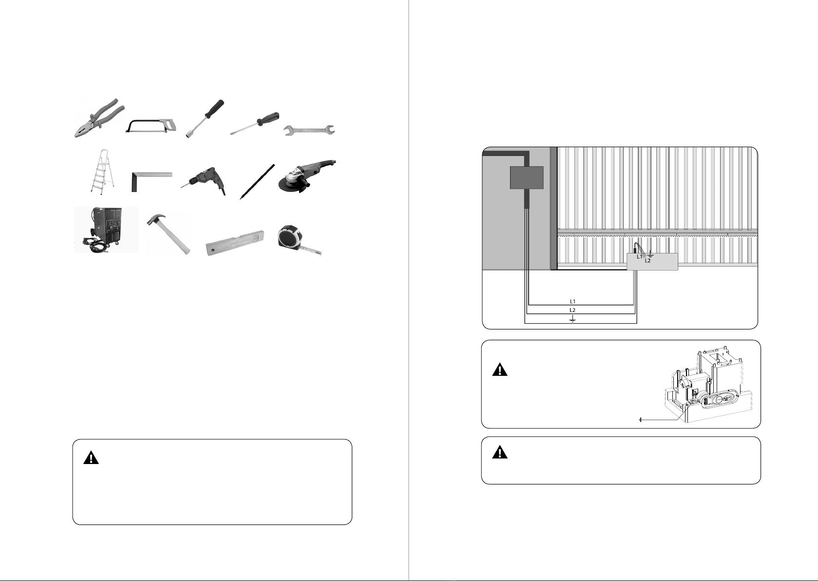
- Before installing the operator, make sure
the local electric power supply is compa-
ti-ble with the one required on the equip-
ment identication label.
- Do not turn on the electric power supply
until installation or maintenance are com-
pleted. Always make the control board
electrical connections with the power su-
pply turned o.
- Once installation is complete, ensure the
gate parts do not extend into the paths and
public sidewalk.
- Using total shutdown devices when ins-
talling an operator is mandatory.
TECHNICAL FEATURES
DZ HUB R 600 DZ HUB R 350
JETFLEX
DZ HUB R 550
JETFLEX
DZ HUB R 450
24V
TYPE OF OPERATOR Sliding Sliding Sliding Sliding
MODEL Single-phase Jetex Jetex Brushless 24V
RATED VOLTAGE 127 V / 220 V 127 V / 220 V 127 V / 220 V 85 – 265 V
NOMINAL FREQUENCY 60 Hz 60 Hz 60 Hz 60 Hz
NOMINAL POWER 250 W / 400 W 280 W / 340 W 450 W / 500 W 50 W
MOTOR ROTATION 1740 RPM 5800 RPM 5800 RPM 2200 RPM
NOMINAL CURRENT 2.3 A / 2.0 A 2.5 A / 2.4 A 4.5 A / 3.5 A 0.7 A
REDUCTION RATIO 1:23 1:23 1:23 1:23
LINEAR SPEED 17.1 m/min (Z18)
20.9 m/min (Z22) 57 m/min (Z18) 57 m/min (Z18) 16,8 m/min (Z14)
21.6 m/min (Z18)
CYCLES/HOUR 30 to 60 30 40 40
DEGREE OF PROTECTION IPX4 IPX4 IPX4 IPX4
TEMPERATURE RANGE -5° C / +50° C -5° C / +50° C -5° C / +50° C -5° C / +50° C
INSULATION TYPE Class B, 130° C Class B, 130° C Class B, 130° C Class B, 130° C
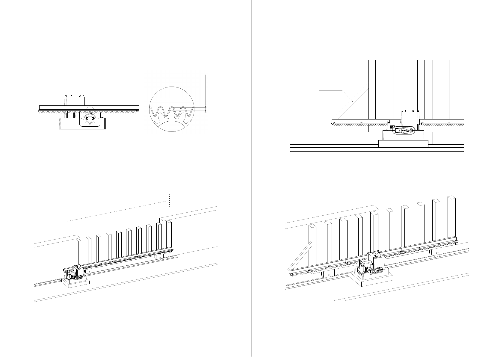
LIMIT SWITCH Analog or Digital Hybrid Hybrid Hybrid
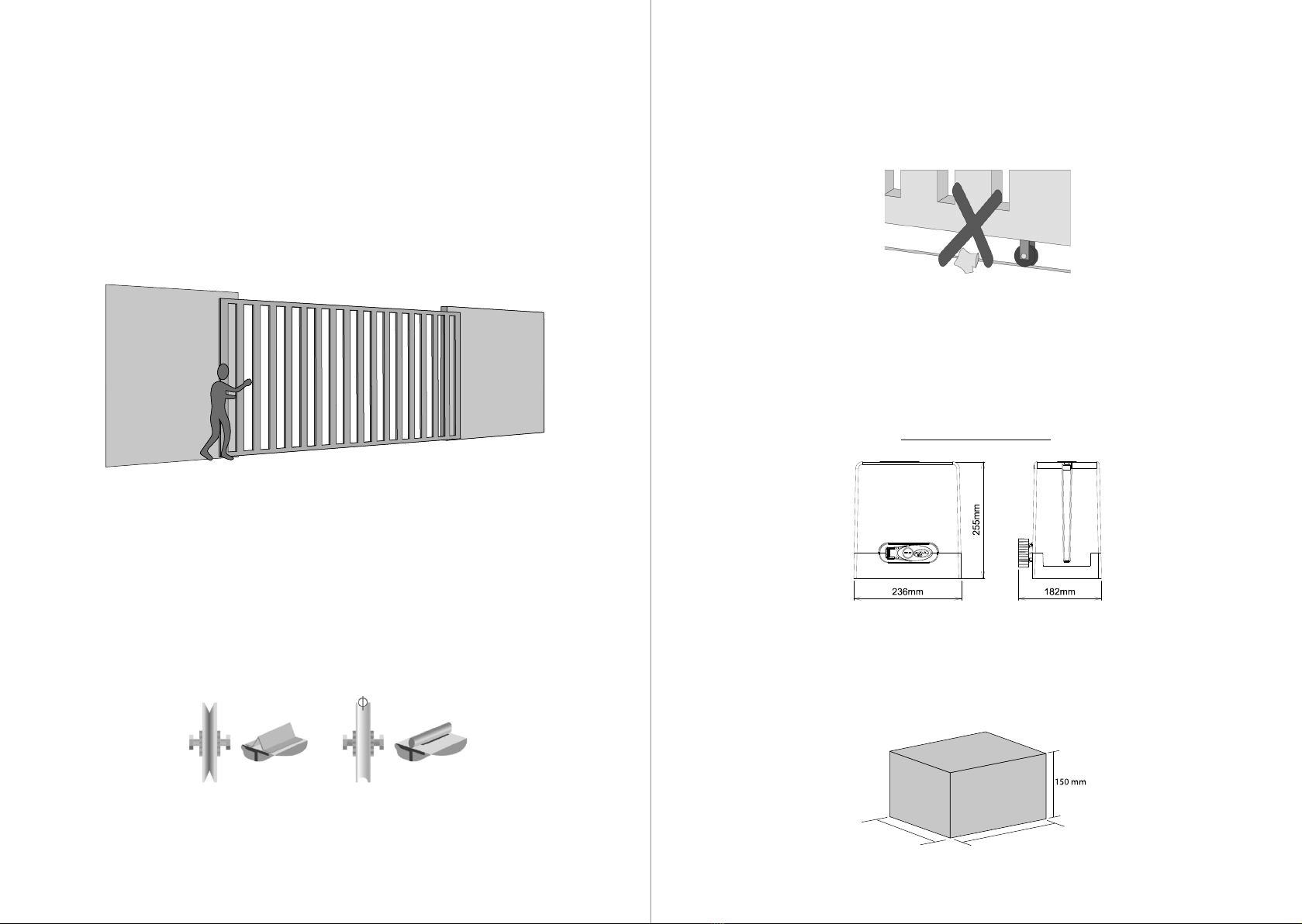
GATE LEAF MAX. MASS 600 Kg 350 Kg 550 Kg 450 Kg
GATE MAX. DIMENSION HEIGHT = 2.5 m
LENGTH = 3.0 m
HEIGHT = 2.5 m
LENGTH = 3.0 m
HEIGHT = 2.5 m
LENGTH = 3.0 m
HEIGHT = 2.5 m
LENGTH = 3.0 m

6 7
TOOLS REQUIRED FOR INTALLATION
Below are some of the tools required to install the operator:
ELECTRICAL INSTALLATION
For the electrical installation, the electrical power supply must have the following
features.
- Power supply: 127 V or 220 V.
- Have 5-A circuit breakers in the electric power distribution box.
- 3/4” diameter conduits between the electrical distribution box and the total shu-
tdown device.
- 3/4”diameter conduits between the total shutdown device and the point
automation connection.
- 1/2”diameter conduits for external and optional push-buttons.
- 1/2”diameter conduit for safety photocells (optional).
- The cable for the xed wiring must comply with NBR NM 247-3.
- The power supply conductor of a product for indoor use must
be a 3 x 0.75-mm² exible cable; 500 V, according to the NM 247-5
NBR norm.
- The power supply conductor of a product for external use
must be a 3 x 0.75-mm² exible cable; 500V, according to the IEC
60245-57 norm.
PLIERS SAW BOW CANNON KEY SCREWDRIVER OPEN-END WRENCH
LADDER
WELDING MACHINE HAMMER LEVEL RULER METERING TAPE
ANGLE RULER DRILL PENCIL SANDERS /
GRINDER
CAUTION WITH THE ELECTRICAL
INSTALLATION
All electrical conductors must be installed on the operator correctly to avoid dama-
ging the wiring. The wiring must run through conduits and internally through the
oor base to en-sure no wiring conductor is trapped or damaged.
- The grounding terminal must
be connected to the mains
grounding cable.
IMPORTANT
The device must be powered via a residual-current device (RCD)
with a rat-ed residual operating current exceeding 30 mA.
SHUTDOWN
MEANS
CONDUIT

8 9
CAUTION WITH THE GATE BEFORE THE
AUTOMATION
Before adapting the operator to the gate, check its sliding according to the
following instructions:
1st step: Before installing the operator, check the gate’s mechanical condi-tions,
that is, if it is closing and opening correctly. Open the gate manually and observe
the eort demanded. This eort must be minimum along the entire gate path.
2nd step: Close the gate manually and check if the eort demanded was the same
as in the previous step.
The gate must have a resistant structure and, as far as possible, one that does not
deform. The diameter of the pulleys must match the dimensions of the gate. The
pulleys must be in perfect running conditions and mount-ed so that the gate leaf
has stability throughout its movement. We recom-mend pulleys with a minimum
diameter of 120 mm.
The gures below represent the two types of rails and pulleys used. The system
that uses a straight section (Figure A – angle bracket) has greater friction and wear.
The circular section (Figure B) allows for better gate movement and less friction for
the operator.
3rd step: Check if the gate leaf does not get stuck in the opening and clos-ing mo-
vements. The gate’s sliding rail must be perfectly straight, leveled, and periodically
cleared of any element or dirt that makes it dicult for the pulleys to slide along its
entire length, as shown in the gure below.
INSTALLING AND FIXING THE
OPERATOR
Before installing the operator, remove all unnecessary cables and turn o any equi-
pment or systems connected to the electrical network.
EQUIPMENT DIMENSIONS
The perfect operation of this equipment depends on the instructions in this manu-
al. To x the equipment, proceed as follows:
1st step: Make sure the oor is rm enough so the equipment can be screwed in
and stay level. If it is not, provide a concrete base according to the following gui-
delines:
210 mm 286 mm
FIGURE A FIGURE B

10 11
2nd step: The base dimensions must be appropriate for the operator dimen-sions.
The concrete base must be approximately 20 mm from the face of the gate leaf.
3rd step: Once the conditions have been met, fully open the gate and posi-tion the
operator close to the face of the gate leaf, keeping 50 mm between the edge of the
gate leaf and the concrete base.
4th step: Pre-align the operator to the gate, position the rack over the gear, and
place the assembly against the gate. Then, mark xing holes on the oor or con-
crete base.
5th step: Drill the holes for xing, and position the operator aligned with the gate.
Before tightening the screws S ¼”x 2 ½”, move the gate to check if it does not touch
the operator during its course. If this occurs, move the operator back.
GATE LEAF
SIDE VIEW
CONCRETE BASE
MARK THE FIXING HOLES
ON THE FLOOR
OPERATOR’S FIXING
HOLES
OPERATOR’S FIXING
HOLES
USE 2 S ¼”X 2 ½”SCREWS
WITH S10 BUSHINGS
USE 2 S ¼”X 2 ½”SCREWS
WITH S10 BUSHINGS
MARK THE FIXING HOLES
ON THE FLOOR

12 13
6th step: With the operator unlocked, position the rack over the gear and align it
with the gate.
Leave approximately 2 mm clearance between the rack tooth’s top and the gear
tooth’s bottom.
7th step: Fix the rack along the entire length of the gate leaf with welding or screw
every 300 or 400 mm.
8th step: Provide shims to ensure rack alignment if the gate leaf is warped. There
are cases where the rack must exceed the length of the sheet. In this case, provide
an angle bracket, so it does not skip the teeth when starting the operator.
9th step: After xing the rack, x the operator on the oor or concrete base, and
tighten the screws.
2 mm CLEARANCE
ANGLE BRACKET
300 or 400 mm 300 or 400 mm

14 15
INSTALLING THE ANALOG LIMIT SWITCH
1st step: With the gate closed, place the magnet support on the rack, positioned in
front of the operator’s REED. This magnet will act as a closing limit switch.
2nd step: Fully open the gate and place the other magnet support on the rack, fa-
cing the operator’s REED. This magnet will act as the opening limit switch.
3rd step: Start the motor and check if the REEDs are shutting down cor-rectly. If
necessary, reverse the board connector.
Once the magnet brackets are xed, make the nal adjustments, moving them to
the right or left, down or up, according to the desired adjustment.
4th step: To nish installing the operator and before operating it, the fair-ing must
be installed and secured with 2 screws 3.5 X 16 mm (available in the kit).
GATE CLOSING
BRACKET ADJUSTMENT
GATE OPENING
MAGNET SUPPORT
MAGNET SUPPORT
REED
REED
MAGNET
SUPPORT
MAGNET
SUPPORT

16
CONTROL BOARD
Check the product label (shown be-
side), which is the operator board.
After that, refer to the control board
manual available for download at
www.ppa.com.br and make all con-
nections and congurations.
Lot:
Code:
Model:
Reduction:
Technology:
Voltage:
Board:
Size:
Assembly:
Fairing:
Gear:
MAINTENANCE
The table below lists some PROBLEMS — DEFECTS, PROBABLE CAUSES, AND
CORRECTIONS — that may occur in your operator. Before any maintenance, turn
o the electrical power supply.
DEFECTS PROBABLE CAUSES CORRECTIONS
The motor does
not turn on / does
not operate
A) Power supply is o
B) Open / blown fuse
C) Locked gate
D) Defective limit switch
A) Make sure the electrical power
supply is connected correctly
B) Replace the fuse with the same
specication
C) Make sure no objects blocking
the gate operation
D) Replace the limit switch system
(analog and/or digital)
The motor is
blocked
A) Inverted motor connection
B) Locked gate or operator
A) Check the motor wires
B) Put in manual mode and check
separately
The electronic
control board
does not accept
command
A) Fuse blown
B) Mains disconnected (power
supply)
C) Defect in the discharged remote
control
D) Transmitter range (remote
control)
A) Replace the fuse
B) Turn on the mains (power supply)
C) Check and change the battery
D) Check the position of the
receiver antenna and, if necessary,
reposition it to ensure the range
The motor only
runs to one of the
sides
A) Inverted motor wires
B) Inverted end-of-course system
C) Defect in the control board
A) Check the motor connection
B) Invert the limit switch connector
(analog and/or digital)
C) Replace the control board
This manual suits for next models
4
Table of contents
Other PPA Gate Opener manuals

PPA
PPA BV POTENZA PREDIAL CUSTOM User manual

PPA
PPA DZ 1500 User manual

PPA
PPA DZ HUB User manual

PPA
PPA Central Agility Pop Connect User manual

PPA
PPA DZ BRUTALLE 3.0T JetFlex User manual

PPA
PPA SPIN User manual

PPA
PPA DZ HOME User manual

PPA
PPA TORE User manual

PPA
PPA PIVOTING User manual

PPA
PPA BV LEVANTE User manual
Popular Gate Opener manuals by other brands

Dea
Dea 202 E Instructions and warnings

RIB
RIB ACG4773 quick start guide

Nice
Nice thor1500 Instructions for installation and use

Total Door Automation
Total Door Automation DKC400Y user manual

Wallace Perimeter Security
Wallace Perimeter Security Kinetic 1 Installation and maintenance manual

Beninca
Beninca RI.15M operating instructions