PPA PIVO CONDOMINIUM INOX User manual

WARNING:
Do not use the equipment
without rst reading the
instruction manual
PIVO
CONDOMINIUM
INOX
Technical Manual
P30458 - 03/2022
Rev. 0
All images in this manual are for illustrative purposes only.
Made by: Motoppar Indústria e Comércio de Automatizadores Ltda
Av. Dr. Labieno da Costa Machado, 3526 - Distrito Industrial - Garça - SP - CEP 17406-200 - Brasil
CNPJ: 52.605.821/0001-55
www.ppa.com.br | +55 14 3407 1000

2 32 3
INDEX IMPORTANT SAFETY INSTRUCTIONS
Recommendation:
For the installation of the equipment, it is
important that the PPA specialized installer
follow all the instructions mentioned in this
technical manual and in the user manual.
Equipped with the user manual, the
installer must present all the information,
uses and safety items of the equipment to
the user.
Before using the operator, read and strictly
follow all instructions contained in this
manual.
-Before installing the operator, make
sure that the local electrical network is
compatible with that required on the
equipment identication label;
-Do not turn on the mains until the
installation / maintenance is completed.
Make the electrical connections of the
command center always with the power
grid turned o;
-After installation, make sure that the gate
parts do not extend over the streets and the
public footpath;
-The use of total shutdown devices is
mandatory when installing the operator.
IMPORTANT SAFETY INSTRUCTIONS........................................................................................ 3
TECHNICAL CHARACTERISTICS .................................................................................................. 4
TOOLS REQUIRED FOR INSTALLATION .................................................................................... 5
ELECTRICAL INSTALLATION ........................................................................................................ 5
GATE CARE BEFORE AUTOMATION .......................................................................................... 7
INSTALLATION AND FIXATION OF OPERATOR ...................................................................... 7
MAINTENANCE ..............................................................................................................................14

4 54 5
TECHNICAL CHARACTERISTICS
TOOLS REQUIRED FOR INSTALLATION
Below are some tools needed to install the operator:
ELECTRICAL INSTALLATION
For electrical installation, the network must contain the following characteristics:
- Mains 127 V or 220 V;
- Have 5 A circuit breakers in the electrical energy distribution box;
- 3/4” diameter conduits between the electrical power distribution box and the
total shutdown device;
- 3/4” diameter conduits between the total shutdown device and the operator
connection point;
- 1/2”diameter conduits for external and optional push buttons;
- 1/2”diameter conduits for safety photocells (mandatory).
PLIERS SAW ARCH CANNON KEY SCREWDRIVER FIXED KEY
LADDER
SOLDERING MACHINE HAMMER LEVEL TAPE
FRAME DRILLING
MACHINE
PENCIL SANDER
*The operator is available in ANALOG, DIGITAL or HYBRID limit switch models. Check the model of the
operator on the product packaging or label.
**Maximum length is determined by the operator model, being Standard (2.0 m), Super (3.5 m) and
Mega (4.5 m).
PISTON CONDOMINIUM PISTON CONDOMINIUM
JETFLEX
PISTON CONDOMINIUM
JETFLEX BRUSHLESS
OPERATOR TYPE Pivoting Pivoting Pivoting
MODEL Single Phase Jet Flex Brushless
RATED VOLTAGE 220 V / 127 V 220 V / 127 V 220V / 127V
NOMINAL FREQUENCY 60 Hz 60 Hz 60 Hz
RATED POWER 395 W / 350 W 150 W 155 W / 195 W
ENGINE ROTATION 1740 RPM 5800 RPM 4500 RPM
ENGINE CURRENT 1.8 A / 2.9 A 1.2 A / 2.1 A 0.7A / 2.1A
REDUCTION 1:23 1:23 1:30
LINEAR SPEED 2.7 m/min 9 m/min 5.4 m/min
MANEUVERS 60 cycles/h 80 cycles/h 90 cycles/h
DEGREE OF
PROTECTION IPX4 IPX4 IPX4
TEMPERATURE RANGE -5°C / +50°C -5°C / +50°C -5°C / +50°C
TYPE OF INSULATION Class B, 130°C Class B, 130°C Class B, 130°C
LIMIT SWITCH Analog / Digital / Hybrid * Analog / Digital / Hybrid * Analog / Digital / Hybrid *
MAXIMUM MASS OF
THE GATE LEAF 300 Kg 350 Kg 350 Kg
MAXIMUM GATE
DIMENSION
HEIGHT = 2.5 m
LENGTH** = (Value
determined according to
the operator model)
HEIGHT = 2.5 m
LENGTH** = (Value
determined according to
the operator model)
HEIGHT = 2.5 m
LENGTH** = (Value
determined according to
the operator model)

6 76 7
- The cable for the xed wiring must comply with NBR NM 247-3;
- The power conductor, of a product for internal use, must be a
exible cable 3 x 0.75 mm²; 500 V, according to the NBR standard
NM 247-5;
- The power conductor, of a product for external use, must be a
exible cable 3 x 0.75 mm²; 500 V, as per IEC standard 60245-57
It is mandatory that the
ground terminal is connected
to the mains ground cable.
IMPORTANT
The instrument shall be powered via a residual dierential current
(DR) device with a nominal residual operating current exceeding 30
mA.
GATE CARE BEFORE AUTOMATION
Before applying the operator to the gate, some procedures must be taken:
-Check the performance of the gate before starting the machine installation;
-Verify the eort required to move the gate. It should be moved smoothly along
the entire route. To check this eort, move the gate at a distance of 80 cm from the
turning point (where the operator exerts force to move);
-The gate must have a resistant structure and, as much as possible, non-deformable.
INSTALLATION AND FIXATION OF
OPERATOR
Before installing the operator, remove all unnecessary cables
and disable any equipment or system connected to the electrical
network.
To install the equipment, follow the steps mentioned below:
The pivoting equipment is supplied with a left or right side. Therefore, for your
identication, follow the instructions below:
-Observing the operator, as shown in the image below, check the position of the
motor cable. If the cable is on the right side, the operator is on the right. If the cable
is on the left side, the operator is on the left.
LEFT RIGHT

8 98 9
To check which leaf of the gate is on the left and which is on the right, stand on the
inside of the property, in front of the gate. In this way, the leaf of the gate that is on
your right side is on the right and the one on your left is on the left.
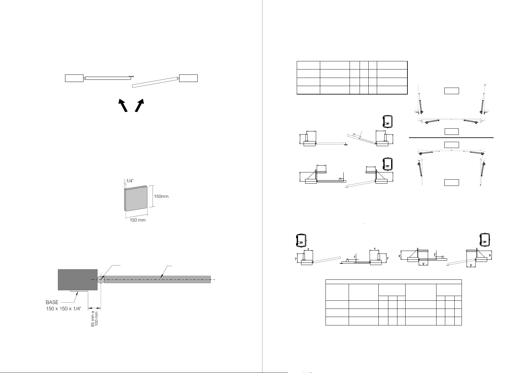
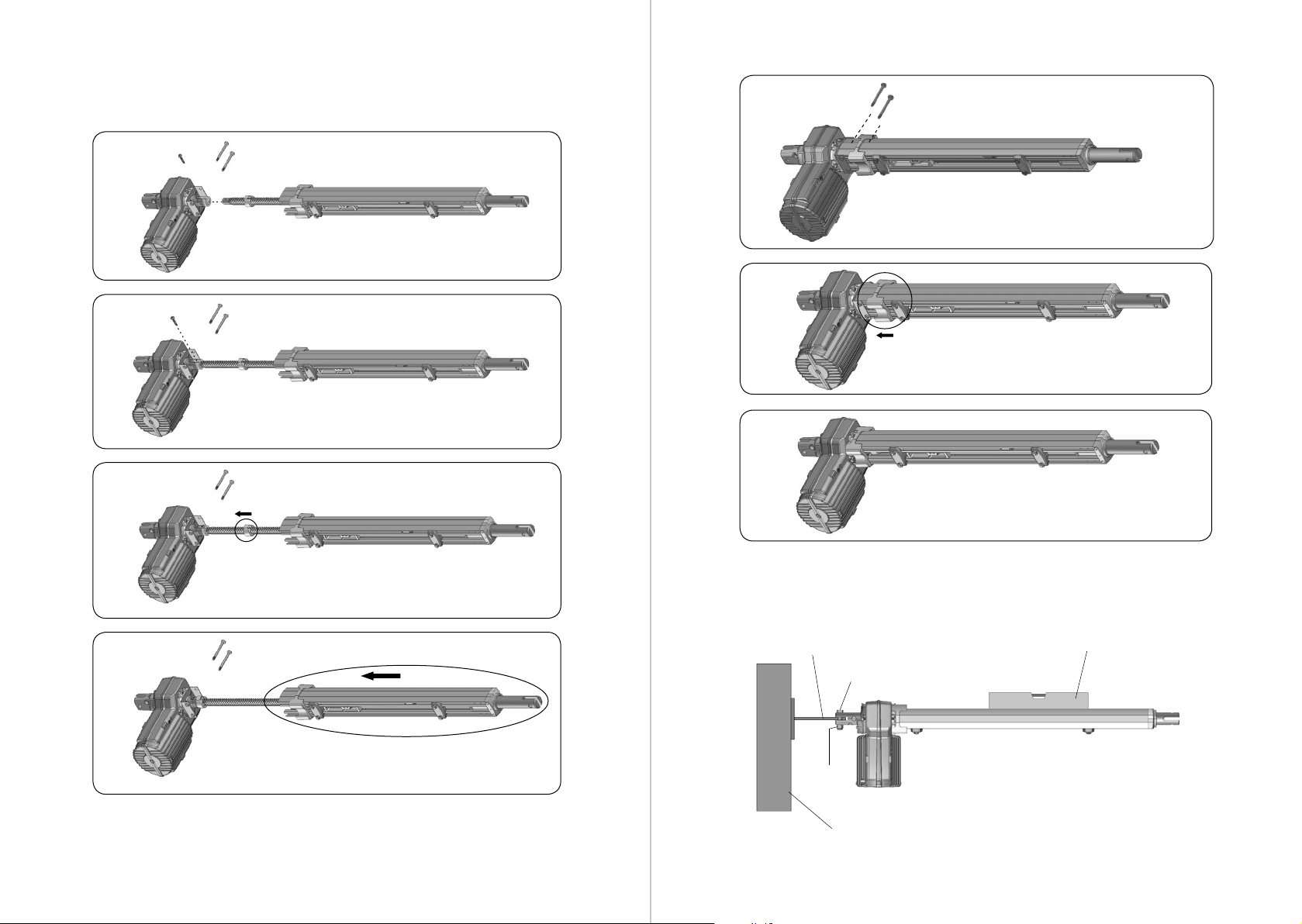
To x the equipment, carefully follow the instructions below:
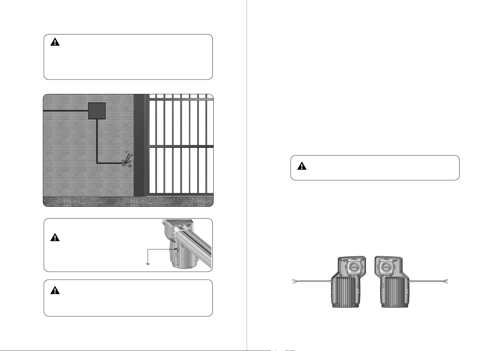
1st Step: The gate must open to the interior of the property. Provide a 150mm x
150mm x 1/4”at iron base. This will be the base of the xture.
2nd Step: Fix, on the wall or on the gate column, the base of the xing bracket at
a distance of 85 to 100 mm from the turning point of the gate and at the desired
height for xing the operator to the gate, as shown in the gure below.
3rd Step: Weld the xing bracket on the base, according to instructions /
illustrations below:
ABERTURA INTERNA (CENTRAL DUPLA)
TABELA DE REFERÊNCIA (CENTRAL DUPLA)
ABERTURA EXTERNA (CENTRAL DUPLA)
yy
xx
z
yy
xx
z
AUTOMATIZADORES
PIVOTANTES
GUIA DE INSTALAÇÃO
P03817 - Rev. 4
Medidas máxima permitidas para instalação padrão (em milímetros).
Retardo Fechamento (RF)
Retardo Abertura (RA)
ACIONAMENTO AUTOMATIZADOR X Y Z
COMPRIMENTO MÁXIMO
DA FOLHA
PIVO HOME 160 160 50 1500
SK 130 130
SK PREDIAL 175 175
PISTON PREDIAL
PISTON CONDOMINIUM
PIVO HOME 270 270
SK 215 215 50 3000
SK PREDIAL 350 350
PISTON PREDIAL
PISTON CONDOMINIUM
SK PREDIAL
PISTON PREDIAL
PISTON CONDOMINIUM
3500
370 370
SUPER
190 190
STANDARD
200050
50
MEGA 400 400 50 4500
ABERTURA EXTERNA (COM RETARDO MECÂNICO)
SUPORTE PARA RETARDO MECÂNICO PPA
ABERTURA INTERNA (COM RETARDO MECÂNICO)
Medida para instalação da chapa
Medidas máxima permitidas para instalação padrão (em milímetros).
STANDARD
ACTIVATION OPERATOR X Y Z MAXIMUM LEAF
LENGTH
STANDARD PISTON
CONDOMINIUM 190 190 50 2000
SUPER PISTON
CONDOMINIUM 370 370 50 3500
MEGA PISTON
CONDOMINIUM 400 400 50 4500
Maximum allowable measurements for standard installation (in
millimeters).
SUPPORT MEASURES FOR INSTALLING PPA PIVOTING OPERATORS WITH MECHANICAL DELAY
ACTIVATION OPERATOR
SLAVE LEAF
Internal opening
or external
LENGTH
MAXIMUM SHEET
MASTER LEAF
X Y Z X Y Z
STANDARD PISTON
CONDOMINIUM 180 180 50 2000 190 190 50
SUPER PISTON
CONDOMINIUM 360 360 50 3500 370 370 50
MEGA PISTON
CONDOMINIUM 390 390 50 4500 400 400 50
Maximum allowable measurements for standard installation (in millimeters).
LEFT LEAF
BASE OF THE
FIXTURE
TURNING POINT GATE LEAF
COLUMN
RIGHT LEAF
INSIDE THE
PROPERTY
REFERENCE TABLE (DOUBLE CENTER)
INTERNAL OPENING (DOUBLE CENTRAL)
INTERNAL OPENING
SUPPORT FOR MECHANICAL DELAY PPA
INTERNAL OPENING (WITH MECHANICAL DELAY) EXTERNAL OPENING (WITH MECHANICAL DELAY)
EXTERNAL OPENING (DOUBLE CENTRAL)
EXTERNAL OPENING
Opening Delay (RA)
STREET
STREET
CLOSED
CLOSED
HOUSE
HOUSE
Opening Delay (RA)
Measure for installing the leaf
Master
Master
Slave Slave
Closing Delay (RF)
Closing Delay (RF)

10 1110 11
4th Step: Couple the gearmotor to the drive, as instructed / illustrated below.
5th Step: Fit the operator to the xing bracket, place the M10 x 45 mm screw and
x it with the M10 hex nut (available in the kit), as shown in the gure below.
FIXING
SUPPORT
M10x45
SCREW
NUT M10
COLUMN
LEVEL

12 1312 13
6th Step: Then, t the sheet xing bracket on the end of the plunger and x it with
M10 x 45 mm screw and M10 hex nut (available in the kit), as shown in the gure
below.
7th Step: With the gate closed, advance the plunger fully and weld the xing
bracket to the gate leaf.
8th Step: Adjust the stops and position the opening and closing limit switches on
the rail, so that they activate when the gate leaf completes its movement. Fix the
limit switch reeds with the 3 x 10 screws (available in the kit) and connect it to the
board.
Before the operator works, it is mandatory to screw board cover
with 4 screws 3.5 x 16 mm (available in kit).
COMMAND BOARD:
Check the label attached to the product
(according to the model on the side)
which is the operator board. Once this is
done, consult the board manual which
is available for download at www. ppa.
com.br and perform all connections
and settings.
Lot:
Code:
Model:
Reduction:
Technology:
Voltage:
Board:
Size:
Mounting:
Fairing:
Gear:
M10x45 SCREW
NUT M10
LEFT LEAF
STOP
STOP
LIMIT SWITCH REED
RIGHT LEAF
GATE OPENING DIRECTION
(INSIDE THE PROPERTY)
FIXING SUPPORT
LEAF
PLUNGER

1414
MAINTENANCE
In the table below, some PROBLEMS will be mentioned — DEFECTS, PROBABLE
CAUSES AND CORRECTIONS — that may occur in your Operator. Before any
maintenance, it is necessary to completely disconnect the electrical network.
DEFECTS PROBABLE CAUSES CORRECTIONS
Engine does not
start / does not
move
A) Power o
B) Open / blown fuse
C) Locked gate
D) Limit switch Defective
A) Make sure the electrical network
is connected correctly
B) Replace fuse with same
specication
C) Make sure there is no object
blocking the gate operation
D) Replace the limit switch system
(analog and/or digital)
Engine blocked A) Inverted motor connection
B) Gate or switch locked
A) Check motor wires
B) Put in manual mode and check
separately
Electronics board
do not accept
command
A) Blown fuse
B) Mains disconnected (power)
C) Defect in remote control
unloaded
D) Transmitter range (remote
control)
A) Replace the fuse
B) Connect the network (power)
C) Check and replace battery
D) Check the position of the receiver
antenna and, if necessary,
reposition it to ensure reach
Motor only runs for
one side
A) Inverted motor wires
B) Inverted limit switch system
C) Defect in command board
A) Check motor connection
B) Invert the limit switch connector
(analog and/or digital)
C) Replace the command board
This manual suits for next models
3
Table of contents
Other PPA Gate Opener manuals
Popular Gate Opener manuals by other brands

BFT
BFT ELI-250 Installation and user manual

Motorline professional
Motorline professional Gateway Control SLIDE 500 Operating and installation instructions

Motorline professional
Motorline professional MC62 User's and installer's manual

Chamberlain
Chamberlain LiftMaster Professional SL585 user manual

Chamberlain
Chamberlain HDLGARM quick start guide

Motorline professional
Motorline professional FIX User's and installer's manual