DK UK FR DE
Ledningskvadrat (min....max.) 0,13...2,08 mm2/ AWG
26...14 flerkoret ledning.
Klemskruetilspændingsmoment 0,5 Nm.
Wire size (min....max.) 0.13...2.08 mm2/
AWG 26...14 stranded wire.
Screw terminal torque 0.5 Nm.
Taille des fils (min....max.) 0,13...2,08 mm2/
AWG 26...14 fils multibrins.
Pression max. avant déformation de la vis 0,5 Nm.
Leitungsquerschnitt (min....max.) 0,13...2,08 mm2/
AWG 26...14 Litzendraht.
Klemmschraubenanzugsmoment 0,5 Nm.
DK
UK
FR
DE
ADVARSEL
Følgende operationer bør kun udføres på
modulet i spændingsløs tilstand og under
ESD-sikre forhold:
Installation, ledningsmontage og -demon-
tage.
Fejlfinding på modulet.
Reparation af modulet må kun foretages af
PR electronics A/S.
ADVARSEL
PR Loop Link programmeringsenheden
må ikke benyttes til kommunikation med
moduler installeret i Ex-område.
Enhederne skal installeres i henhold til
den tilhørende installationsvejledning
ved montering i eksplosionfarlig område.
System 6300 skal monteres på DIN-skin-
ne efter DIN EN 60715.
SIKKERHEDSREGLER
Modtagelse og udpakning
Udpak modulet uden at beskadige det. Kontrollér ved
modtagelsen, at modultypen svarer til den bestilte.
Indpakningen bør følge modulet, indtil dette er mon-
teret på blivende plads.
Miljøforhold
Undgå direkte sollys, kraftigt støv eller varme, me-
kaniske rystelser og stød, og udsæt ikke modulet for
regn eller kraftig fugt. Om nødvendigt skal opvarm-
ning, ud over de opgivne grænser for omgivelses-
temperatur, forhindres ved hjælp af ventilation.
Installation
Modulet må kun tilsluttes af kvalificerede teknikere,
som er bekendte med de tekniske udtryk, advarsler
og instruktioner i installationsvejledningen, og som
vil følge disse.
Hvis der er tvivl om modulets rette håndtering, skal
der rettes henvendelse til den lokale forhandler eller
alternativt direkte til PR electronics A/S.
Installation og tilslutning af modulet skal følge lan-
dets gældende regler for installation af elektrisk
materiel bl.a. med hensyn til ledningstværsnit, for-
sikring og placering.
Beskrivelse af indgang / udgang og forsyningsfor-
bindelser findes i produktmanualen og på sideskiltet.
Kalibrering og justering
Under kalibrering og justering skal måling og til-
slutning af eksterne spændinger udføres i henhold
til denne installationsvejledning, og teknikeren skal
benytte sikkerhedsmæssigt korrekte værktøjer og
instrumenter.
Rengøring
Modulet må, i spændingsløs tilstand, rengøres med
en klud let fugtet med destilleret vand.
PC-programmering af SYSTEM 6300
Modulet konfigureres til den aktuelle opgave ved
hjælp af en PC og PR electronics A/S’ kommunika-
tionsinterface Loop Link. Det er muligt at konfigu-
rere modulet både med og uden tilsluttet forsynings-
spænding, idet kommunikationsinterfacet leverer
nødvendig forsyning til opsætningen. Kommunika-
tionsinterfacet er galvanisk isoleret, så PC’ens port
er optimalt beskyttet. Kommunikationen er 2-vejs,
så modulets opsætning kan hentes ind i PC’en, og
opsætningen i PC’en kan sendes til modulet. For de
brugere, der ikke selv vil foretage opsætning, kan
modulet leveres konfigureret efter oplyst specifikati-
on: indgangstype, måleområde, følerfejlsdetektering
og udgangssignal.
Elektriske specifikationer
Specifikationsområde............. -40°C til +85°C
Forsyningsspænding DC
6333A....................................... 8...35 VDC
6333B....................................... 8...30 VDC
Maks. forbrug, 1 / 2 kanaler,
6333A .......................................... 0,8 W / 1,6 W
Maks. forbrug, 1 / 2 kanaler,
6333B .......................................... 0,7 W / 1,4 W
Internt effekttab, 6333A ..... 0,19...0,8 W
Internt effekttab, 6333B...... 0,19...0,7 W
Kalibreringstemperatur ......... 20...28°C
Relativ fugtighed..................... < 95% RH (ikke kond.)
Mål ................................................. 109 x 23,5 x 104 mm
Kapslingsklasse........................ IP20
Indgangstyper:
Pt100............................................ -200°C...+850°C
Ni100............................................ -60°C...+250°C
Lin. R............................................. 0 Ω...10000 Ω
Strømudgang:
Signalområde............................. 4...20 mA
Min. signalområde.................... 16 mA
Belastningsmodstand, Ω....... ≤ (Vforsyn.-8,0 V)/0,023
Godkendelser:
EAC Ex.......................................... RU C-DK.
НА65.В.00355/19
Overholdte myndighedskrav:
EMC................................................ 2014/30/EU
RoHS ............................................. 2011/65/EU
ATEX .............................................. 2014/34/EU
EAC................................................. TR-CU 020/2011
EAC Ex.......................................... TR-CU 012/2011
WARNING
The following operations should only be
carried out on a disconnected device and
under ESD safe conditions:
General mounting, connection and
disconnection of wires.
Troubleshooting the device.
Repair of the device must be done by PR
electronics A/S only.
WARNING
Do not use the Loop Link programming
interface to program the units in Ex area.
For installation in classified area the
modules must be installed according to
the appropriate installation drawings.
SYSTEM 6300 must be mounted on a DIN
rail according to DIN EN 60715.
SAFETY INSTRUCTIONS
Receipt and unpacking
Unpack the device without damaging it. The packing
should always follow the device until this has been
permanently mounted. Check at the receipt of the
device whether the type corresponds to the one
ordered.
Environment
Avoid direct sunlight, dust, high temperatures,
mechanical vibrations and shock, as well as rain and
heavy moisture. If necessary, heating in excess of
the stated limits for ambient temperatures should be
avoided by way of ventilation.
Mounting
Only qualified technicians who are familiar with the
technical terms, warnings, and instructions in this
installation guide and who are able to follow these
should connect the device.
Should there be any doubt as to the correct handling
of the device, please contact your local distributor or,
alternatively, PR electronics A/S.
Mounting and connection of the device should
comply with national legislation for mounting of
electric materials, i.e. wire cross section, protective
fuse, and location. Descriptions of input / output and
supply connections are shown in the product manual
and on the side label.
Calibration and adjustment
During calibration and adjustment, the measuring
and connection of external voltages must be
carried out according to the specifications of this
installation guide. The technician must use tools and
instruments that are safe to use.
Cleaning
When disconnected, the device may be cleaned with
a cloth moistened with distilled water.
PC programming of SYSTEM 6300
The device is configured to the present task by way
of a PC and PR electronics A/S’ communications
interface Loop Link. The device can be configured
with or without a connected supply voltage as the
communications interface supplies the necessary
voltage to the set-up. The communications interface
is galvanically isolated to protect the PC port.
Communication is 2-way to allow the retrieval of
the device set-up into the PC and to allow the
transmission of the PC set-up to the device. For
users who do not wish to do the set-up themselves,
the device can be delivered configured according to
customer specifications: input type, measurement
range, sensor error detection, and output signal.
Electrical specifications
Specifications range............... -40°C to +85°C
Supply voltage, DC
6333A....................................... 8...35 VDC
6333B....................................... 8...30 VDC
Max. required power,
1 / 2 channels, 6333A........... 0.8 W / 1.6 W
Max. required power,
1 / 2 channels, 6333B........... 0.7 W / 1.4 W
Internal power dissipation,
6333A .......................................... 0.19...0.8 W
Internal power dissipation,
6333B .......................................... 0.19...0.7 W
Calibration temperature ........ 20...28°C
Relative humidity..................... < 95% RH (non-cond.)
Dimensions................................. 109 x 23.5 x 104 mm
Protection degree.................... IP20
Input types:
Pt100............................................ -200°C...+850°C
Ni100............................................ -60°C...+250°C
Lin. R............................................. 0 Ω...10000 Ω
Current output:
Signal range............................... 4...20 mA
Min. signal range...................... 16 mA
Load resistance, Ω.................... ≤ (Vsupply-8.0 V)/0.023
Approvals:
EAC Ex.......................................... RU C-DK.
НА65.В.00355/19
Observed aothority requirements:
EMC................................................ 2014/30/EU
RoHS ............................................. 2011/65/EU
ATEX .............................................. 2014/34/EU
EAC................................................. TR-CU 020/2011
EAC Ex.......................................... TR-CU 012/2011
AVERTISSEMENT
Les opérations suivantes doivent être
eectuées avec le module débranché
et dans un environnement exempt
de décharges électrostatiques (ESD):
Montage général, raccordement et
débranchement de fils et recherche de
pannes sur le module.
Seule PR electronics SARL est autorisée à
réparer le module.
AVERTISSEMENT
Ne pas utiliser le kit de programmation
“Loop Link” en zone classée dangereuse
Ex. Pour des installations en zone
classée, les modules doivent être monté
conformément aux plans appropriés.
Il convient de monter l’appareil SYSTEME
6300 sur un rail DIN en se conformant à la
norme DIN EN 60715.
CONSIGNES DE SECURITE
Réception et déballage
Déballez le module sans l’endommager. Il est
recommandé de conserver l’emballage du module
tant que ce dernier n’est pas définitivement monté.
A la réception du module, vérifiez que le type de
module reçu correspond à celui que vous avez
commandé.
Environnement
N’exposez pas votre module aux rayons directs du
soleil et choisissez un endroit à humidité modérée
et à l’abri de la poussière, des températures élevées,
des chocs et des vibrations mécaniques et de la
pluie. Le cas échéant, des systèmes de ventilation
permettent d’éviter qu’une pièce soit chauée au-
delà des limites prescrites pour les températures
ambiantes.
Montage
Il est conseillé de réserver le raccordement du module
aux techniciens qualifiés qui connaissent les termes
techniques, les avertissements et les instructions
de ce guide et qui sont capables d’appliquer ces
dernières.
Si vous avez un doute quelconque quant à la
manipulation du module, veuillez contacter votre
distributeur local. Vous pouvez également vous
adresser à : PR electronics SARL.
Le montage et le raccordement du module doivent
être conformes à la législation nationale en vigueur
pour le montage de matériaux électriques, par ex-
emple, diamètres des fils, fusibles de protection
et implantation des modules. Les connexions des
alimentations et des entrées / sorties sont décrites
dans le manuel du produit et sur l’étiquette de la face
latérale du module.
Etalonnage et réglage
Lors des opérations d’étalonnage et de réglage, il
convient d’eectuer les mesures et les connexions
des tensions externes en respectant les spécifica-
tions mentionnées dans ce guide. Les techniciens
doivent utiliser des outils et des instruments
pouvant être manipulés en toute sécurité.
Maintenance et entretien
Une fois le module hors tension, prenez un chion
imbibé d’eau distillée pour le nettoyer.
Programmation par PC du SYSTEME 6300
Le module peut être programmé en fonction d’une
application donnée à partir d’un PC et le kit de
programmation Loop Link de PR electronics A/S. Le
module peut être programmé sans être alimenté car
l’interface de communication fournit l’alimentation
nécessaire pour la configuration. L’interface de
communication est doté d’une isolation galvanique
pour protéger le port du PC. La communication
est bidirectionnelle. Cela permet non seulement
la programmation du module mais également la
récupération d’une configuration existante ainsi
que la lecture du numéro de série et du repère. Le
module peut être livré déjà programmé, si l’utilisateur
le souhaite.
Spécifications
Plage de température............ -40°C à +85°C
Tension d’alimentation, cc
6333A....................................... 8...35 Vcc
6333B....................................... 8...30 Vcc
Puissance maximale requise,
1 / 2 voies, 6333A.................. 0,8 W / 1,6 W
Puissance maximale requise,
1 / 2 voies, 6333B.................. 0,7 W / 1,4 W
Puissance dissipée, 6333A... 0,19...0,8 W
Puissance dissipée, 6333B... 0,19...0,7 W
Température d’étalonnage... 20...28°C
Humidité relative ..................... < 95% HR (sans cond.)
Dimensions................................. 109 x 23,5 x 104 mm
Degré de protection................ IP20
Types d’entrée :
Pt100............................................ -200°C...+850°C
Ni100............................................ -60°C...+250°C
Résistance linéaire.................. 0 Ω...10000 Ω
Sortie courant :
Gamme de signal...................... 4...20 mA
Plage de signal min................. 16 mA
Résistance de charge, Ω........ ≤ (Valim.-8,0 V)/0,023
Approbations :
EAC Ex.......................................... RU C-DK.
НА65.В.00355/19
Compatibilité avec les normes:
CEM................................................ 2014/30/UE
RoHS ............................................. 2011/65/UE
ATEX .............................................. 2014/34/UE
EAC................................................. TR-CU 020/2011
EAC Ex.......................................... TR-CU 012/2011
WARNUNG
Folgende Maßnahmen sollten nur in span-
nungslosem Zustand des Gerätes und
unter ESD-sicheren Verhältnisse durchge-
führt werden: Installation, Montage und
Demontage von Leitungen. Fehlersuche
im Gerät und Reparaturen des Gerätes
dürfen nur von PR electronics A/S vorge-
nommen werden.
WARNUNG
Benutzen Sie die Programmierschnitt-
stelle Loop Link nicht im Ex Bereich.
Zur Montage in klassifizierten Zonen
müssen die Geräte nach den dazuge-
hörigen Einbauzeichnungen installiert
werden.
Das System 6300 muss auf eine DIN-
Schiene nach DIN EN 60715 montiert
werden.
SICHERHEITSREGELN
Empfang und Auspacken
Packen Sie das Gerät aus, ohne es zu beschädigen,
und kontrollieren Sie beim Empfang, ob der Gerä-
tetyp Ihrer Bestellung entspricht. Die Verpackung
sollte beim Gerät bleiben, bis dieses am endgültigen
Platz montiert ist.
Umgebungsbedingungen
Direkte Sonneneinstrahlung, starke Staubentwick-
lung oder Hitze, mechanische Erschütterungen und
Stöße sind zu vermeiden; das Gerät darf nicht Regen
oder starker Feuchtigkeit ausgesetzt werden. Bei Be-
darf muss eine Erwärmung, welche die angegebenen
Grenzen für die Umgebungstemperatur überschreitet,
mit Hilfe eines Kühlgebläses verhindert werden.
Installation
Das Gerät darf nur von qualifizierten Technikern an-
geschlossen werden, die mit den technischen Aus-
drücken, Warnungen und Anweisungen in dieser Ins-
tallationsanleitung vertraut sind und diese befolgen.
Sollten Zweifel bezüglich der richtigen Handhabung
des Gerätes bestehen, sollte man mit dem Händler
vor Ort Kontakt aufnehmen. Sie können aber auch
direkt mit PR electronics GmbH Kontakt aufnehmen.
Die Installation und der Anschluss des Gerätes haben
in Übereinstimmung mit den geltenden Regeln des
jeweiligen Landes bez. der Installation elektrischer
Apparaturen zu erfolgen, u.a. bezüglich Leitungs-
querschnitt, (elektrischer) Vor-Absicherung und Po-
sitionierung.
Eine Beschreibung von Eingangs- / Ausgangs- und
Versorgungsanschlüssen befindet sich im Produkt-
manual und auf dem Typenschild.
Kalibrierung und Justierung
Während der Kalibrierung und Justierung sind die
Messung und der Anschluss externer Spannungen
entsprechend dieser Installationsanleitung auszu-
führen, und der Techniker muss hierbei sicherheits-
mäßig einwandfreie Werkzeuge und Instrumente
benutzen.
Reinigung
Das Gerät darf in spannungslosem Zustand mit ei-
nem Lappen gereinigt werden, der mit destilliertem
Wasser leicht angefeuchtet ist.
PC-Programmierung des Systems 6300
Das Gerät wird für die jeweilige Aufgabe mit Hilfe
eines PCs und PR electronics A/S Kommunikations-
schnittstelle Loop Link konfiguriert. Es ist möglich,
das Gerät sowohl mit als auch ohne angeschlos-
sene Versorgungsspannung zu konfigurieren, da
die Kommunikationsschnittstelle die notwendige
Versorgung für die Einstellung liefert. Die Kommu-
nikationsschnittstelle ist galvanisch isoliert, sodass
der Anschluss des PCs optimal geschützt ist. Die
Kommunikation erfolgt in beiden Richtungen, sodass
die Einstellung des Gerätes in den PC geholt, und
die Einstellung im PC an das Gerät gesandt werden
kann. Für diejenigen Anwender, welche die Einstel-
lung nicht selbst vornehmen wollen, kann das Gerät
nach folgenden Kundenspezifikationen konfiguriert
geliefert werden: Eingangstyp, Messbereich, Fühler-
fehlererkennung und Ausgangssignal.
Elektrische Daten
Spezifikationsbereich............. -40°C bis +85°C
Versorgungsspannung, DC
6333A....................................... 8...35 VDC
6333B....................................... 8...30 VDC
Leistungsbedarf, max.,
1 / 2 Kanäle, 6333A............... 0,8 W / 1,6 W
Leistungsbedarf, max.,
1 / 2 Kanäle, 6333B............... 0,7 W / 1,4 W
Verlustleistung, 6333A......... 0,19...0,8 W
Verlustleistung, 6333B......... 0,19...0,7 W
Kalibrierungstemperatur....... 20...28°C
Luftfeutigkeit............................ < 95% RF (nicht kond.)
Maß................................................ 109 x 23,5 x 104 mm
Schutzart..................................... IP20
Eingangs-Typen:
Pt100............................................ -200°C...+850°C
Ni100............................................ -60°C...+250°C
Lin. R............................................. 0 Ω...10000 Ω
Stromausgang:
Signalbereich............................. 4...20 mA
Min. Signalbereich.................... 16 mA
Belastungswiderstand, Ω...... ≤ (VVers.-8,0 V)/0,023
Zulassungen:
EAC Ex.......................................... RU C-DK.
НА65.В.00355/19
Eingehaltene Behördenvorschriften:
EMV................................................ 2014/30/EU
RoHS ............................................. 2011/65/EU
ATEX .............................................. 2014/34/EU
EAC................................................. TR-CU 020/2011
EAC Ex.......................................... TR-CU 012/2011
6334
13 (23)
11 (21)
*
*
Loop
Link 5909 - USB
FileProductInputOutputCommunication LanguageOption08:30:00
PRetop5331
Date:2004-8-10
043201594
PRelectronics
AnaloginputAnalogoutput
Serialno:
Inputtype:Outputtype:4-20mA
Upscale
Sensorerror:
Pt100DIN/IEC
0.00-50.00C
3-wire
1.00sec
------
Inputrange:
Connection:
Coldjunctioncomp:
Responsetime:
Tagno:
Disconnect
+Vsupply
*Connectedonlyfor
on-lineprogramming
Black
Red Yellow
Green
Input
Receiving
equipment
Connector
63xx
Loop Link er et kommunikationsinterface, der er nødvendigt for programmering af
63xx. Loop Link må ikke benyttes til kommunikation med moduler installeret i Ex-
område.
Loop Link is a communications interface that is needed for programming 63xx. Loop
Link is not approved for communication with devices installed in hazardous (Ex) areas.
Loop Link est un kit de programmation permettant de programmer les 63xx. Loop
Link ne doit pas être utilisé pour communication avec des modules installés en zone
dangereuse.
Loop Link ist eine Schnittstelle zur Programmierung des 63xx. Loop Link darf nicht zur
kommunikation mit Geräten, die in Ex-gefährdeten Bereichen installiert sind, benutz
werden.
UK
DK
FR
DE
Frigørelse fra DIN-skinne
Husk først at demontere tilslutningsklemmerne med
farlig spænding. Modulet frigøres fra DIN-skinnen ved
at løfte i den nederste lås.
Demounting from DIN rail
First, remember to demount the connectors with
hazardous voltages. Detach the device from the DIN
rail by lifting the bottom lock.
Démontage du rail DIN
Tout d’abord, n’oubliez pas de démonter les connecteurs
où règnent des tensions dangereuses. Débloquez le
verrou inférieur pour dégager le module du rail DIN.
Lösen von DIN-Schiene
Zunächst ist gefährliche Spannung von den Anschluss-
klemmen zu trennen. Das Gerät wird von der DIN-
Schiene gelöst, indem man den unteren Verschluss
löst.
DK
UK
FR
DE
Montering på DIN-skinne.
Mounting on DIN rail.
Montage sur rail DIN.
Montage auf DIN-Schiene.
DK
UK
FR
DE
DK Ex-godkendelser UK I.S approvals FR Approbations S.I. DE Ex-Zulassungen
ATEX Area Installation
drawing IECEx Area Installation
drawing FM Area Installation
drawing CSA Area Installation
drawing
6333A DEKRA 20ATEX 0106 X 2, 22 6333QA02 DEK 20.0062X 2, 22 6333QI02 FM17US0013X 2 / Div 2 6333QF01 1125003 2 / Div 2 6333QC02
6333B DEKRA 20ATEX 0105 X 0, 1, 2, 21, 22, M1 6333QA01 DEK 20.0062X 0, 1, 2, 21, 22, M1 6333QI01 FM17US0013X 0, 1, 2 / Div 1 6333QF01 1125003 0 , 1, 2 / Div 1 6333QC01
DK UK FR DE
A Indgangssignaler Input signals Signaux d’entrée Eingangssignale
B Udgangssignaler Output signals Signaux de sortie Ausgangssignale
C RTD, 3-leder RTD, 3-wire RTD, 3-fils WTH, 3-Leiter
D RTD, 2-leder RTD, 2-wire RTD, 2-fils WTH, 2-Leiter
F Modstand, 3-leder Resistance, 3-wire Résistance, 3-fils Widerstand, 3-Leiter
F Modstand, 2-leder Resistance, 2-wire Résistance, 2-fils Widerstand, 2-Leiter
G
6333A
Forsyning
+ 8,0...35 VDC
6333A
Supply
+ 8.0...35 VDC
6333A
Alimentation
+ 8,0...35 Vcc
6333A
Versorgung
+ 8,0...35 VDC
H
6333B
Forsyning
+ 8,0...30 VDC
6333B
Supply
+ 8.0...30 VDC
6333B
Alimentation
+ 8,0...30 Vcc
6333B
Versorgung
+ 8,0...30 VDC
I4...20 mA udgang 4...20 mA output Sortie 4...20 mA 4...20 mA-Ausgang
Ch.1 Kanal 1 Channel 1 Voie 1 Kanal 1
Ch.2 Kanal 2 Channel 2 Voie 2 Kanal 2
44
43
42
41
44
43
42
41
13
12
11
23
22
21
54
53
52
51
Ch.2
Ch.1
B
A
A
+
+-
+
+-
I
G/H
I
G/H
B
Ch.2
Ch.1
C
3
E
3
DF
C
3
E
3
DF
Part Name
Hazardous Substances
Lead
(Pb) Mercury
(Hg) Cadmium
(Cd)
Hexavalent
Chromium
(Cr (VI))
Polybrominated
biphenyls
(PBB)
Polybrominated
diphenyl ethers
(PBDE)
Printed
circuit board X O O O O O
This table is prepared in accordance with the provisions of SJ/T 11364
O: Indicates that said hazardous substance contained in all of the homogeneous materials for this
part is below the limit requirement of GB/T 26572.
X: Indicates that said hazardous substance contained in at least one of the homogeneous materials
used for this part is above the limit requirement of GB/T 26572.
The product’s Environmentally Friendly Use Period (EFUP) is 50 years 50
DK Kina RoHS UK China RoHS FR RoHS chinois DE China-RoHS
PR electronics A/S • Lerbakken 10 • DK-8410 Rønde • Tel. +45 8637 2677 • www.prelectronics.com
DK
Dokumentation, godkendelser og yderligere information
findes på internettet på www.prelectronics.dk
UK
Documentation, permits and other information can be
found on the internet at www.prelectronics.com
FR
La documentation et toute autre information peuvent
être trouvées sur l’Internet sur notre site:
www.prelectronics.fr
DE
Dokumentationen, Zulassungen und andere Informatio-
nen können auf unserer Internet-Seite unter
www.prelectronics.de gefunden und abgerufen werden.
SN56333_107 (2220)
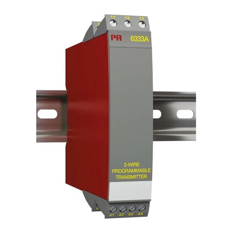
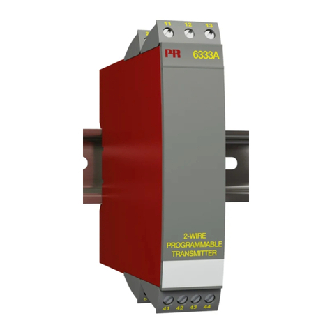
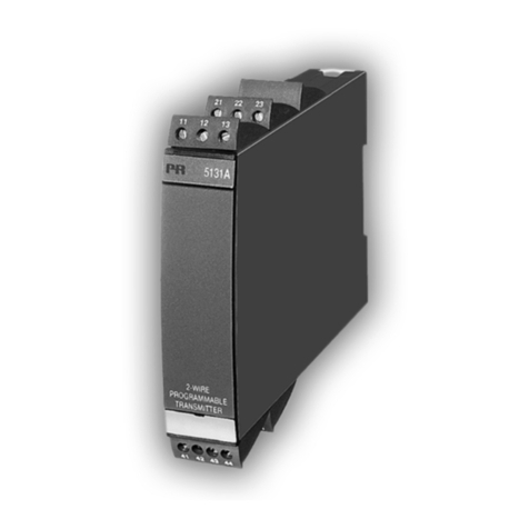
6333A & 6333B
6333A 6333B Installationsvejledningen for teknikere omfatter følgende
produkter: 6333A og 6333B.
The installation guide for technical personnel covers the
following products: 6333A and 6333B.
Le guide d’installation pour le personnel qualifié couvre les
produits suivants: 6333A et 6333B.
Die Installationsanleitung für Techniker umfasst die
folgenden Produkte: 6333A und 6333B.
DK
UK
FR
DE
DK Sideskilt UK Side label FR Etiquette DE Typenschild
Godkendelser.
Approvals.
Homologations.
Zulassungen.
Typenr.
Type no.
No. de type.
Typennr.
}
}
DK
UK
FR
DE
DK
UK
FR
DE
Benforbindelser.
Pin connections.
Raccordement
des bornes.
Klemmen-
anschluss.
}DK
UK
FR
DE


