Pro-face GC4000 Series User manual

http://www.proface.com.cn
简体中文 English
GC4000 Series Installation Guide
GC4000 Series
Installation Guide
10/2011

2
English

English
3
Important Information
NOTICE
Read these instructions carefully, and look at the equipment to become
familiar with the device before trying to install, operate, or maintain it. The
following special messages may appear throughout this documentation or on
the equipment to warn of potential hazards or to call attention to information
that clarifies or simplifies a procedure.

4
English
PLEASE NOTE
Electrical equipment should be installed, operated, serviced, and maintained
only by qualified personnel. No responsibility is assumed by Pro-face for any
consequences arising out of the use of this material.
A qualified person is one who has skills and knowledge related to the
construction and operation of electrical equipment and its installation, and
has received safety training to recognize and avoid the hazards involved.
suke Pro!" at http://www.pro-face.com/otasuke/.
Product Related Information
DANGER
HAZARD OF ELECTRIC SHOCK, EXPLOSION OR ARC FLASH
Disconnect all power from all equipment including connected devices
prior to removing any covers or doors, or installing or removing any
accessories, hardware, cables, or wires except under the specific
conditions specified in the appropriate hardware guide for this
equipment.
Always use a properly rated voltage sensing device to confirm the power
is off.
Unplug the power cable from both the equipment and the power supply.
Replace and secure all covers, accessories, hardware, cables, and
wires and confirm that a proper ground connection exists before
applying power to the equipment.
Use only the specified voltage when operating this equipment and any
associated products.
Failure to follow these instructions will result in death or serious
injury.

English
5
WARNING
LOSS OF CONTROL
Consider the potential failure modes of control paths in the machine
control system design, such as:
The possibility of backlight failure,
Unanticipated link transmission delays or failures,
The operator being unable to control the machine,
The operator making errors in the control of the machine.
Provide a means to achieve a safe state during and after a path failure
for critical control functions such as emergency stop and overtravel stop.
Provide separate or redundant control paths for critical control functions.
Test individually and thoroughly each implementation of the panel for
correct operation before service.
Failure to follow these instructions can result in death, serious injury,
or equipment damage.

6
English

English
7
GC4000 Series of Panels
GC4000 Part Numbers
The following table presents the different GC4000 panels:
Package Contents
Make sure all items listed here are included in the panel package.:
1 Panel
2 DC power connector
3 Screw installation fasteners (GC4408W and GC4401W: x4, GC4501W: x6)
4 GC4000 Installation guide
Part number Screen size USB
type A
USB
type mini B
RS232 RS422/
RS485
RTC
battery
GC4408W 17.78 cm (7 in.) No Yes Yes1Yes1No
GC4401W 17.78 cm (7 in.) Yes Yes Yes Yes Yes
GC4501W 25.65 cm (10.1 in.) Yes Yes Yes Yes Yes
1If "COM1" (RS232) is selected, COM2 (RS422/RS485) cannot be used. If "COM2"
(RS422/RS485) is selected, COM1 (RS232) cannot be used.

8
English
Handling the LCD panel
If the panel is damaged and any liquid comes in contact with your skin,
immediately rinse the area with running water for at least 15 minutes If the
liquid gets in your eyes, immediately rinse your eyes with running water for
at least 15 minutes and consult a doctor.
Product Label Sticker
You can identify the product version (PV) and the revision level (RL) from the
product label on the panel.
The following diagram is a representation of a typical label:
CAUTION
SERIOUS EYE AND SKIN INJURY
The LCD panel’s liquid contains an irritant. Avoid direct skin contact with the
liquid.
Wear gloves when you handle a broken or leaking panel.
Do not use sharp objects or tools in the vicinity of the LCD touch panel.
Handle the LCD panel carefully to prevent puncture, bursting, or
cracking of the panel material.
Failure to follow these instructions can result in injury or equipment
damage.

English
9
GC4000 Parts Identification
Side GC4408W GC4•01W
Front
Rear
Bottom
Part Description
A LED Indicator
B Touch panel
C Replaceable battery for RTC
D USB (Type mini B)
E Screw installation fasteners (GC4408W and GC4401W: x4, GC4501W: x6)
F Power connector
G Serial Interface COM1 (RS232)
H Serial Interface COM2 (RS485/RS422)
I USB (Type A)

10
English
Installation
Panel-cut
Create a panel-cut and insert the panel from the front. The following
illustration shows the panel-cut for the GC4000 series:
Panel-cut Dimensions
The following table shows the panel-cut dimensions for each panel:
Installation Fasteners
Mount the panel in an enclosure that provides a clean, dry, robust and
controlled environment (IP65 enclosure) (see GC4000 Series Hardware
Manual, ).
The fasteners are used to mount the GC4000 series:
Model A B C (Panel
Thickness)
R
GC440•W 190 mm (7.48 in)
± 1 mm (0.04 in)
135 mm (5.31 in)
±0.7 mm (0.03 in)
1.5...10 mm
(0.06...0.39 in)
3 mm
(0.12 in)
max.
GC4501W 255 mm (10.04 in)
± 1.8 mm (0.07 in)
185 mm (7.28 in)
+1 mm (0.04 in) -
0mm
1.5...10 mm
(0.06...0.39 in)
3 mm
(0.12 in)
max.
Model Screw Installation Fasteners
GC440•W 4
GC4501W 6

English
11
Panel Setup Procedure
Stage Description
1 Check that the installation panel or the surface of the cabinet is flat, in good
condition and has no jagged edges. Metal reinforcing strips may be attached to the
inside of the panel wall, near the panel-cut, to increase the rigidity of the panel.
2 Decide on the installation the thickness of the panel based on the level of panel
strength required: 1.5 mm (0.06 in.) to 10 mm (0.4 in.).
3 Be sure that the ambient operation temperature and the ambient humidity are
within their designated ranges. (When installing the panel in a cabinet or
enclosure, the ambient operation temperature is the internal temperature of the
cabinet or enclosure.)
4 Be sure that heat from surrounding equipment does not cause the panel to exceed
its standard operating temperature (see GC4000 Series Hardware Manual, ).
5 When installing the panel in a vertical position, the logo on the panel face must be
on the right side to keep the power connector at the top.

12
English
Panel Mounting Procedure
6 When installing the panel in a slanted position, the panel face should not incline
more than 30°.
When installing the panel in a slanted position, and the panel face inclines more
than 30°, the ambient temperature must not exceed 40 °C. You may need to use
forced air cooling (fan, A/C) to ensure the ambient operating temperature is 40°C
or below.
7 For easier maintenance, operation and improved ventilation, install the panel at
least 100 mm (3.94 in.) away from adjacent structures and other equipment as
shown in the following illustration:
Stage Description
NOTICE
PANEL UNSTEADY WHEN UNSECURED
Keep panel stabilized in the panel-cut while you are installing or removing
the screw fasteners.
Failure to follow these instructions can result in equipment damage.

English
13
Step Action
1 Place the panel on a clean and level surface with the display face pointing
downward.
2 Check that the gasket of the panel is seated securely which runs around the
perimeter of the frame.
3 Create the correct sized opening required to install the panel, using the installation
dimensions (see GC4000 Series Hardware Manual, ).
4 Insert the panel into the panel-cut.
5 Insert the installation fasteners into the panel‘s insertion slots on the top and
bottom sides (and left and right sides for the GC4501W). Slide the fasteners flat
against the panel. If the fasteners are not correctly attached, the panel may shift or
fall out.
6 Use a Phillips screwdriver to tighten each fastener and secure the panel in place.
The necessary torque is 0.8...1 Nm (7.08...8.85 lb-in):
NOTICE
BROKEN ENCLOSURE
Do not exert more than 1 Nm (8.85 in-lb) of torque when tightening the
fastener’s screws.
Failure to follow these instructions can result in equipment damage.
14
English
Installing and Replacing the RTC Battery
While lithium batteries are preferred due to their slow discharge and long life,
they can present hazards to personnel, equipment and the environment, and
must be handled properly.
NOTE: Replace battery only with identical type: Renata Type CR2032.
To install or replace the RTC battery, follow these steps:
DANGER
EXPLOSION, FIRE, OR CHEMICAL HAZARD
Follow these instructions for the lithium batteries:
Replace with identical type.
Follow all battery manufacturer’s instructions.
Remove all replaceable batteries before discarding panel.
Recycle or properly dispose of used batteries.
Protect battery from any potential short circuit.
Do not recharge, disassemble, heat above 100 °C (212 °F), or
incinerate.
Use your hands or insulated tools to remove or replace the battery.
Maintain proper polarity when inserting and connecting a new battery.
Failure to follow these instructions will result in death or serious
injury.
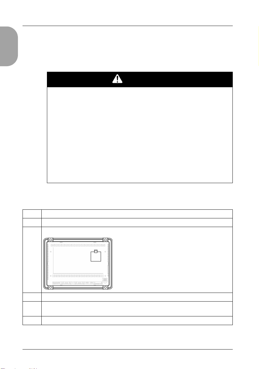
Step Action
1 Power off your panel.
2Open the cover to access the backup battery compartment as shown below:
3 Remove the used battery from the compartment.
4 Insert the new battery in the compartment in accordance with the polarity markings in
the compartment and on the battery.
5 Close the cover and verify that the latch clicks into place.

English
15
NOTE: Replacement of the panel’s battery other than with the type specified
in this documentation may present a risk of fire or explosion.
6 Power up your GC4000.
NOTE: If you do not power up your GC4000 immediately, the external backup battery life may be
significantly reduced.
7 Set the internal clock. For further details on the internal clock, please refer to
Adjusting the clock on the display (see the GP-Pro EX screen editor).
Step Action

16
English
Wiring Principles
Connecting the Power Cord
Follow these instructions when supplying power to the panel:
When the functional ground (FG) terminal is connected, be sure the wire
is grounded. Not grounding the panel can result in excessive
Electromagnetic Interference (EMI). Grounding is required to meet EMC
level immunity.
The shield ground (SG) and FG terminals are connected internally in the
panel.
Disconnect the power before wiring the panel’s power terminals.
The panel uses only 24 Vdc power. Using any other level of power can
damage both the power supply and the panel.
Since the panel is not equipped with a power switch, be sure to connect a
power switch to the panel’s power supply.
Be sure to ground the panel’s FG terminal.
Power Cord Preparation
Make sure the ground wire is either the same or heavier gauge than the
power wires.
Do not use aluminum wires in the power supply’s power cord.
If the ends of the individual wires are not twisted correctly, the wires may
create a short circuit. To avoid this, use D25CE/AZ5CE cable ends.
Wherever possible, use wires that are 0.75 to 2.5 mm2(AWG 18 - 12) for
the power cord, and twist the wire ends before attaching the terminals.
The conductor type is solid or stranded wire.
Power Plug Illustration
Connection Wire
+24Vdc
-0Vdc
FG Grounded terminal connected to the panel chassis.

English
17
How to Connect the Power Cord
The following table explains how to connect the power plug:
NOTE:
Do not solder the wire directly to the power receptacle pin.
The power supply cord should meet the specification shown above. Be
sure to twist the power cords together, up to the power plug, for EMC
cancellation.
Connecting the Power Supply
Connect the power cord to the power connector on the side of the panel
using the power plug.
Between the line and the ground, be sure to use a regulated power supply
with a Class 2 power supply.
To increase the electromagnetic noise resistance, be sure to twist the
ends of the power cord wires before connecting them to the power plug.
The panel’s power supply cord should not be bundled with or kept close
to main circuit lines (high voltage, high current), or input/output signal
lines.
Connect a lightning surge absorber to handle power surges.
To reduce electromagnetic noise, make the power cord as short as
possible.
Step Action
1 Remove the power cord from the power supply.
2 Remove the power plug from the panel.
3 Remove 7 mm (0.28 in.) of the vinyl cover off the ends of the power cord wires.
4 If using stranded wire, twist the ends. Tinning the ends with solder reduces risk of
fraying and ensures good electrical transfer.
5 Connect the wires to the power plug by using a flat-bladed screwdriver (size
0.6 X 3.5).
6 Tighten the mounting screws using the defined torque: 0.5...0.6 nm (5...7 lb-in).
7 Replace the power plug onto the power connector.

18
English
Power Supply Connections
For ease of maintenance, use the following connection diagram to set up
your power supply connections.
NOTE:
Ground the surge absorber (E1) separately from the panel (E2).
Select a surge absorber that has a maximum circuit voltage greater than
that of the peak voltage of the power supply.
The following shows a lightning surge absorber connection:
WARNING
SHORT CIRCUITS, FIRE, OR UNINTENDED EQUIPMENT OPERATION
Avoid excessive force on the power cable to prevent accidental
disconnection:
Securely attach power cables to the panel or cabinet.
Use the torque 0.8...1 Nm (7.08...8.85 in-lb) to tighten the panel’s
terminal block screws.
Install and fasten panel on installation panel or cabinet prior to
connecting Power Supply and Communication lines.
Failure to follow these instructions can result in death, serious injury,
or equipment damage.

English
19
Grounding
Take the following precautions for grounding the panel. Connect the
functional ground (FG) terminal on the power plug to an exclusive ground.
Grounding Procedure
Common Grounding
Electromagnetic Interference (EMI) can be created if the devices are
improperly grounded. EMI can cause loss of communication.
Do not use common grounding, except for the authorized configuration
described below.
Step Action
1Check that the grounding resistance is less than 0.1 Ω(1).
2The FG wire should have a cross sectional area greater than 2 mm (1). Create the
connection point as close to the panel as possible, and make the wire as short as
possible. When using a long grounding wire, replace the thin wire with a thicker
wire, and place it in a duct.
3 If the equipment does not function properly when grounded, disconnect the ground
wire from the FG terminal.
(1) Observe local codes and standards. Ensure the ground connection has a resistance of less
than 0.1 Ωand that the ground wire has a cross-section of at least 2 mm2or AWG 14.

20
English
If exclusive grounding is not possible, use a common connection point.
Other manuals for GC4000 Series
1
This manual suits for next models
3
Table of contents
Other Pro-face Monitor manuals

Pro-face
Pro-face Xycom SXT1811 Installation instructions

Pro-face
Pro-face GP-4000M User manual

Pro-face
Pro-face PL-X900 Series User manual

Pro-face
Pro-face SP5000 Series User manual

Pro-face
Pro-face FP-790T User manual

Pro-face
Pro-face PS-3000B Series User manual

Pro-face
Pro-face SP-5600TP User manual

Pro-face
Pro-face FP3650-T41 User manual

Pro-face
Pro-face GP-3600T Series User manual

Pro-face
Pro-face GP577R-TC11 User manual


