Pro-face GP-4201TM User manual

GP-4201TM/4301TM/4000M
Hardware Manual

GM4000 Series Hardware Manual
2
The information provided in this documentation contains general descriptions and/or
technical characteristics of the performance of the products contained herein. This
documentation is not intended as a substitute for and is not to be used for
determining suitability or reliability of these products for specific user applications. It
is the duty of any such user or integrator to perform the appropriate and complete
risk analysis, evaluation and testing of the products with respect to the relevant
specific application or use thereof. Neither Pro-face nor any of its affiliates or
subsidiaries shall be responsible or liable for misuse of the information contained
herein. If you have any suggestions for improvements or amendments or have found
errors in this publication, please notify us.
No part of this document may be reproduced in any form or by any means, electronic
or mechanical, including photocopying, without express written permission of Pro-
face.
All pertinent state, regional, and local safety regulations must be observed when
installing and using this product. For reasons of safety and to help ensure
compliance with documented system data, only the manufacturer should perform
repairs to components.
When devices are used for applications with technical safety requirements, the
relevant instructions must be followed.
Failure to use Pro-face software or approved software with our hardware products
may result in injury, harm, or improper operating results.
Failure to observe this information can result in injury or equipment damage.
Copyright © 2014.11 Digital Electronics Corporation. All Rights Reserved.

3
Table of Contents
Table of Contents
Safety Information . . . . . . . . . . . . . . . . . . . . . . . . . . . . . . . . . . 5
About the Book. . . . . . . . . . . . . . . . . . . . . . . . . . . . . . . . . . . . . 7
Chapter 1 General Overview . . . . . . . . . . . . . . . . . . . . . . . . . . . . . . . . . . . 9
Package Contents . . . . . . . . . . . . . . . . . . . . . . . . . . . . . . . . . . . . . . . . . . . . . . 10
Parts Identification and Functions . . . . . . . . . . . . . . . . . . . . . . . . . . . . . . . . . . 13
Certifications and Standards . . . . . . . . . . . . . . . . . . . . . . . . . . . . . . . . . . . . . . 16
Chapter 2 Device Connectivity . . . . . . . . . . . . . . . . . . . . . . . . . . . . . . . . . 19
System Design. . . . . . . . . . . . . . . . . . . . . . . . . . . . . . . . . . . . . . . . . . . . . . . . . 20
Accessories . . . . . . . . . . . . . . . . . . . . . . . . . . . . . . . . . . . . . . . . . . . . . . . . . . . 24
Chapter 3 Specifications . . . . . . . . . . . . . . . . . . . . . . . . . . . . . . . . . . . . . . 27
3.1 General Specifications . . . . . . . . . . . . . . . . . . . . . . . . . . . . . . . . . . . . . . . . . . 28
General Specification. . . . . . . . . . . . . . . . . . . . . . . . . . . . . . . . . . . . . . . . . . . . 28
3.2 Functional Specifications . . . . . . . . . . . . . . . . . . . . . . . . . . . . . . . . . . . . . . . . 30
Display . . . . . . . . . . . . . . . . . . . . . . . . . . . . . . . . . . . . . . . . . . . . . . . . . . . . . . . 31
Memory, Clock, and Touch Panel . . . . . . . . . . . . . . . . . . . . . . . . . . . . . . . . . . 32
3.3 Interface Specifications . . . . . . . . . . . . . . . . . . . . . . . . . . . . . . . . . . . . . . . . . . 33
Interface Specifications . . . . . . . . . . . . . . . . . . . . . . . . . . . . . . . . . . . . . . . . . . 34
Specifications of Serial Interface COM1 . . . . . . . . . . . . . . . . . . . . . . . . . . . . . 35
3.4 Dimensions . . . . . . . . . . . . . . . . . . . . . . . . . . . . . . . . . . . . . . . . . . . . . . . . . . . 37
Display Module GP-4201TM . . . . . . . . . . . . . . . . . . . . . . . . . . . . . . . . . . . . . . 37
Display Module GP-4301TM . . . . . . . . . . . . . . . . . . . . . . . . . . . . . . . . . . . . . . 38
Rear Module (for all GP units) . . . . . . . . . . . . . . . . . . . . . . . . . . . . . . . . . . . . . 39
Display and Rear Modules GP-4201TM . . . . . . . . . . . . . . . . . . . . . . . . . . . . . 40
Display and Rear Modules GP-4301TM . . . . . . . . . . . . . . . . . . . . . . . . . . . . . 41
Cable Attached Dimensions . . . . . . . . . . . . . . . . . . . . . . . . . . . . . . . . . . . . . . 42
Separation Cable Attached Dimension . . . . . . . . . . . . . . . . . . . . . . . . . . . . . . 43
DIN Rail Attached Demention . . . . . . . . . . . . . . . . . . . . . . . . . . . . . . . . . . . . . 43
Chapter 4 Installation and Wiring. . . . . . . . . . . . . . . . . . . . . . . . . . . . . . . 45
4.1 Installation . . . . . . . . . . . . . . . . . . . . . . . . . . . . . . . . . . . . . . . . . . . . . . . . . . . . 46
Panel Cut-out Dimensions and Installation . . . . . . . . . . . . . . . . . . . . . . . . . . . 47
Installation Procedures . . . . . . . . . . . . . . . . . . . . . . . . . . . . . . . . . . . . . . . . . . 51
4.2 Wiring Principles . . . . . . . . . . . . . . . . . . . . . . . . . . . . . . . . . . . . . . . . . . . . . . . 57
Connecting the Power Cord. . . . . . . . . . . . . . . . . . . . . . . . . . . . . . . . . . . . . . . 58
Connecting the Power Supply . . . . . . . . . . . . . . . . . . . . . . . . . . . . . . . . . . . . . 60
Grounding . . . . . . . . . . . . . . . . . . . . . . . . . . . . . . . . . . . . . . . . . . . . . . . . . . . . 62
4.3 USB Interface . . . . . . . . . . . . . . . . . . . . . . . . . . . . . . . . . . . . . . . . . . . . . . . . . 64
Important Considerations When Using the USB interface. . . . . . . . . . . . . . . . 65
USB Data Transfer Cable (ZC9USCBMB1) - USB Driver Installation . . . . . . . 66
USB (Type A) interface . . . . . . . . . . . . . . . . . . . . . . . . . . . . . . . . . . . . . . . . . . 67
USB (mini-B) interface . . . . . . . . . . . . . . . . . . . . . . . . . . . . . . . . . . . . . . . . . . . 70
Chapter 5 Maintenance . . . . . . . . . . . . . . . . . . . . . . . . . . . . . . . . . . . . . . . 73
Regular Cleaning . . . . . . . . . . . . . . . . . . . . . . . . . . . . . . . . . . . . . . . . . . . . . . . 74

GP-4201TM/4301TM/4000M Hardware Manual
4
Periodic Check Points . . . . . . . . . . . . . . . . . . . . . . . . . . . . . . . . . . . . . . . . . . . 74
After-sales service . . . . . . . . . . . . . . . . . . . . . . . . . . . . . . . . . . . . . . . . . . . . . . 74

5
§
Safety Information
Safety Information
Important Information
NOTICE
Read these instructions carefully, and look at the equipment to become familiar with
the device before trying to install, operate, or maintain it. The following special
messages may appear throughout this documentation or on the equipment to warn
of potential hazards or to call attention to information that clarifies or simplifies a
procedure.
The addition of this symbol to a Danger or Warning safety label
indicates that an electrical hazard exists which will result in personal
injury if the instructions are not followed.
This is the safety alert symbol. It is used to alert you to potential
personal injury hazards. Obey all safety messages that follow this
symbol to avoid possible injury or death.
DANGER
DANGER indicates a hazardous situation which, if not avoided, will result in death
or serious injury.
WARNING
WARNING indicates a hazardous situation which, if not avoided, could result in
death or serious injury.
CAUTION
CAUTION indicates a hazardous situation which, if not avoided, could result in
minor or moderate injury.
NOTICE
NOTICE is used address practices not related to physical injury.

GP-4201TM/4301TM/4000M Hardware Manual
6
PLEASE NOTE
Electrical equipment should be installed, operated, serviced, and maintained only by
qualified personnel. No responsibility is assumed by Pro-face for any consequences
arising out of the use of this material.
A qualified person is one who has skills and knowledge related to the construction
and operation of electrical equipment and the installation, and has received safety
training to recognize and avoid the hazards involved.

7
About the Book
About the Book
At a Glance
Thank you for purchasing Pro-face's GP-4201TM/4301TM/4000M (Hereafter
referred to as the "GP unit").
Document Scope
This manual describes how to use the GP unit.
Validity Note
This documentation is valid for the GP unit when used with GP-Pro EX version 4.02
or later.
The technical characteristics of the device(s) described in this manual appear
online. To access this information online, please go to our site
http://www.pro-face.com/.
The characteristics presented in this manual should be constantly improved for
clarity and accuracy. In the event that you see a difference between the manual in
your PC and online information, use the online information as your reference.
Product Related Information
Related Documents
You can download these technical publications and other technical information from
our website at http://www.pro-face.com/trans/en/manual/1001.html.
WARNING
UNINTENDED EQUIPMENT OPERATION
The application of this product requires expertise in the design and programming
of control systems. Only persons with such expertise should be allowed to
program, install, alter, and apply this product.
Follow all local and national safety codes and standards.
Failure to follow these instructions can result in death, serious injury, or
equipment damage.
Title of Documentation
GP-Pro EX Reference Manual
GP-Pro EX Device/PLC Connection Manual
GP-Pro EX Maintenance/Troubleshooting
GP-4201TM/4301TM/4000M Hardware Manual
8
Model Name Indication
Model name
PFXGM4
*
**
T
A
D
GP-4201TM/4301TM/4000M Model Names
Global Code
A global code is assigned to every Pro-face product as a universal model number.
For more information on product models and their matching global codes, please
refer to the following URL.
http://www.pro-face.com/trans/en/manual/1003.html
ABCE
D
A
2 GP-4200 series (3.5-inch): QVGA (320 x 240 dots)
3 GP-4300 series (5.7-inch): QVGA (320 x 240 dots)
B No display (Rear Module)
B 01 RS-232C/RS-422/RS-485
CT TFT color LCD
- No display (Rear Module)
DA Analog Touch Panel
- No display (Rear Module)
E D DC type power supply is used.
Series Names Models
GP4000 Series
GP-4200 Series GP-4201TM
(Modular Type) PFXGM4201TAD
GP-4300 Series GP-4301TM
(Modular Type) PFXGM4301TAD
GP-Rear Module GP-4000M
(Rear Modular Type) PFXGM4B01D

9
General Overview
1
EIO0000000614 07/2010
General Overview
Overview
This chapter describes the GP unit's General Overview.
What's in this Chapter?
This chapter contains the following topics:
Topic Page
Package Contents 10
Parts Identification and Functions 13
Certifications and Standards 16

GP-4201TM/4301TM/4000M Hardware Manual
10
Package Contents
Package Contents
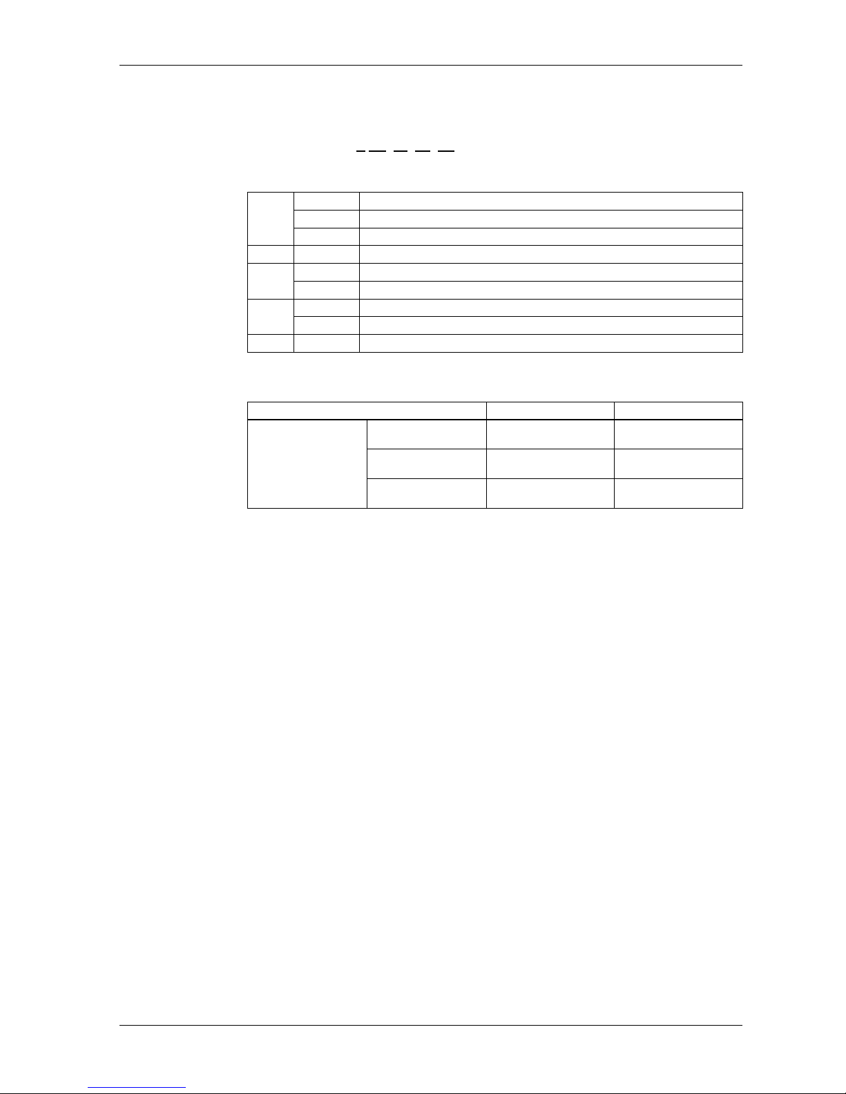
Verify all items listed here are present in your package:
*1. Display Module and Rear Module
Product Label Sticker
You can identify the product version (PV), revision level (RL) and software version
(SV) from the product label on the panel.
The following diagram is a representation of a typical label:
When PV is 03 or later and SV is 3.0 or later, GP can also be used as a rear module.
Legend Description
Package Type
GP *1 Display
Module
Rear
Module
1 Display Module Yes Yes No
2 Rear Module Yes No Yes
3 Socket Wrench Yes No No
4 USB Clamp Type A (1Port) Yes No Yes
5 Anti-rotation Tee Yes Yes No
6 DC Power Supply Connector Yes No Yes
7Display Installation Nut
(Attached to the Display Module) Yes Yes No
8GP-4201TM/4301TM/4000M
Installation Guide Yes Yes Yes
9 Warning/Caution Information Yes Yes Yes
21 3
65
4
789
395/69

General Overview
11
Critical systems, Detected Alarms and Handling Requirements
Critical detected alarm indicators and system functions require independent and
redundant protection hardware and/or mechanical interlocks.
If the unit for any reason becomes inoperative (for example, an inoperative
backlight) it may be difficult or impossible to identify a function. Functions that may
present a hazard if not immediately executed, such as emergency stop, must be
provided independently of the unit. The design of the control system must take into
account an inoperative unit (backlight) and that the operator is unable to control the
machine or respond to detected errors using the unit.
When the power is cycled, wait at least 10 seconds before restoring the power to the
GP Unit. Switching the power OFF and ON quickly can damage the unit.
WARNING
LOSS OF CONTROL
Consider the potential failure modes of control paths in the machine control
system design, such as:
The possibility of backlight failure,
Unanticipated link transmission delays or failures,
The operator being unable to control the machine,
The operator making errors in the control of the machine.
Provide a means to achieve a safe state during and after a path failure for critical
control functions such as emergency stop and overtravel stop.
Provide separate or redundant control paths for critical control functions.
Test individually and thorougly each implementation of the GP unit for correct
operation before service.
Failure to follow these instructions can result in death, serious injury, or
equipment damage.
WARNING
UNINTENDED EQUIPMENT OPERATION
Do not use the unit as the only means of control for critical system functions
such as motor start/stop or power control.
Do not use the unit as the only notification device for critical alarms, such as
device overheating or overcurrent.
Failure to follow these instructions can result in death, serious injury, or
equipment damage.
GP-4201TM/4301TM/4000M Hardware Manual
12
Handling the LCD Panel
The following characteristics are specific to the LCD unit and are considered normal
behavior:
LCD screen may show unevenness in the brightness of certain images or may
appear different when seen from outside the specified viewing angle. Extended
shadows, or cross-talk, may also appear on the sides of screen images.
LCD screen pixels may contain black and white colored spots and color display
may seem to have changed over time.
When the same image is displayed on the screen for a long period, an after-
image may appear when the image is changed.
NOTE: Do not display the same image for a long time, change the screen image
periodically.
Using Touch Panel Correctly
Use only one finger to select an object on the touch panel.
If the touch panel receives pressure at two or more points at the same time, an
unintended object could be selected.
CAUTION
SERIOUS EYE AND SKIN INJURY
The liquid present in the LCD panel contains an irritant:
Avoid direct skin contact with the liquid.
Wear gloves when you handle a broken or leaking unit.
Do not use sharp objects or tools in the vicinity of the LCD touch panel.
Handle the LCD panel carefully to prevent puncture, bursting, or cracking of the
panel material.
If the panel is damaged and any liquid comes in contact with your skin, immediately
rinse the area with running water for at least 15 min.
If the liquid gets in your eyes, immediately rinse your eyes with running water for
at least 15 minutes and consult a doctor.
Failure to follow these instructions can result in injury or equipment damage.
WARNING
UNINTENDED EQUIPMENT OPERATION
Operate the GP unit touch panel with only one finger.
Do not activate two or more points of the touch panel simultaneously.
Failure to follow these instructions can result in death, serious injury, or
equipment damage.

General Overview
13
Parts Identification and Functions
Display Module
Front:
A Display: displays user created screens and remote equipment variables.
B Touch panel: performs screen change operations and sends data to the host (PLC).
Rear:
A, B
GP-4201TM/4301TM/4000M Hardware Manual
14
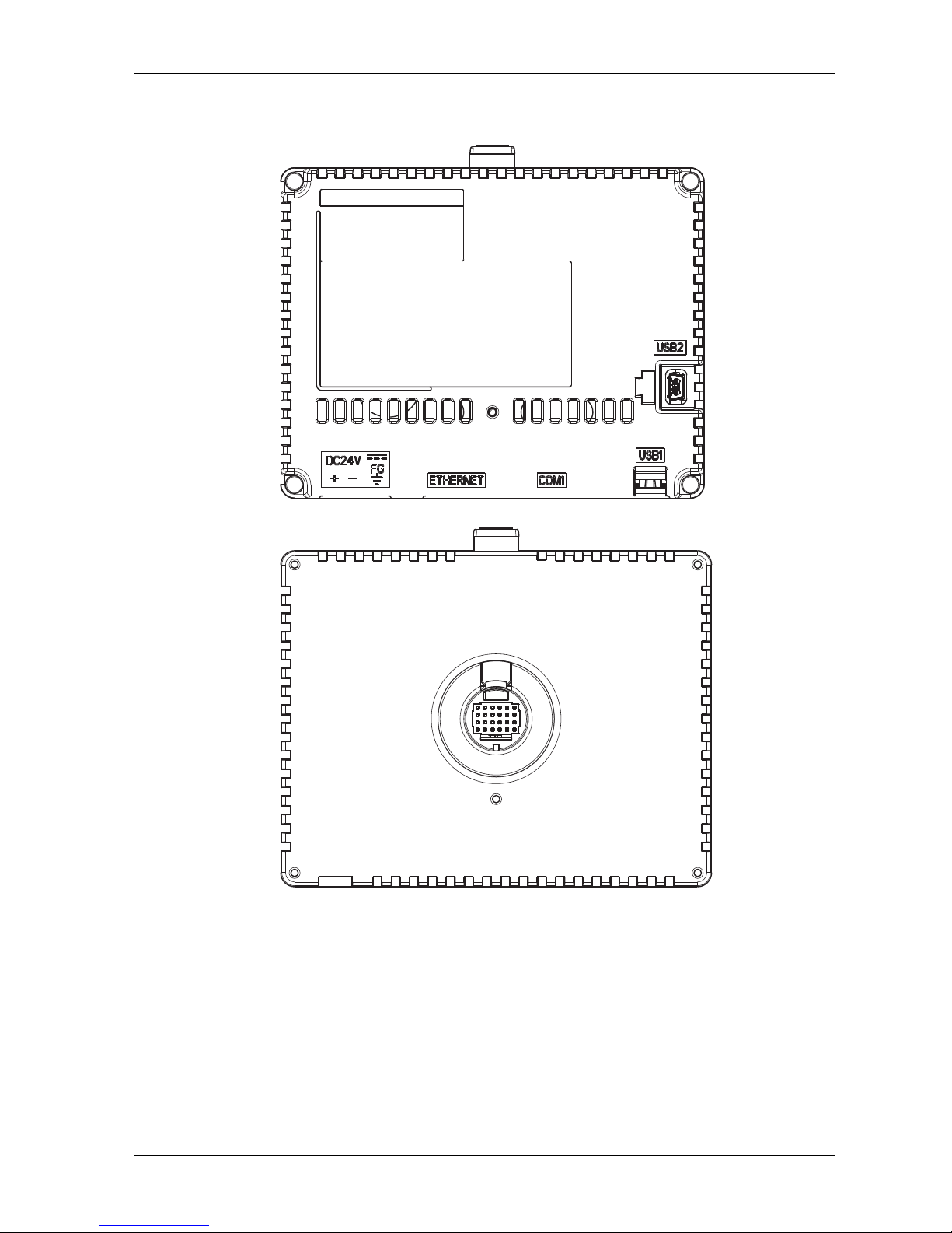
Rear Module
Front:
Rear:

General Overview
15
Connectors:
Bottom:
C USB (Type A) interface connector: connects the memory stick to the unit.
D Serial I/F (host I/F): connects a RS232C/RS422/RS485 cable (from the host/PLC) to the
GP unit. D-Sub 9-pin plug type connector.
E Ethernet Interface (LAN): connects an Ethernet cable (from the host/PLC) to the unit.
F DC Power Supply Connector: connects the power input and ground wires to the unit.
Side:
G USB (mini-B) interface connector: connects the data transfer PC cable to the unit.
C D EF
G

GP-4201TM/4301TM/4000M Hardware Manual
16
Certifications and Standards
Introduction
Pro-face submitted this product for independent testing and qualification by third-
party listing agencies. These agencies have certified this product as meeting the
following standards.
For information on Standards and Regulations, such as certified models and
certificates, see the following.
http://www.pro-face.com/trans/en/manual/1002.html
Agency Certifications for GP Unit
GP unit is certified by the Underwriters Laboratory according to:
UL 508 and CSA C22.2 n142 for Industrial Control Equipment
ANSI/ISA 12.12.01 and CSA C22.2 n213 for Electrical Equipment for Use in Class
I, Division 2 Groups A, B, C and D Hazardous (classified) Locations
NOTE:
For use in Pollution Degree 2 environments.
For use on a flat surface of Type 4X Enclosure.
Hazardous Substances
GP unit is designed for compliance with:
WEEE, Directive 2012/19/EU
RoHS, Directive 2011/65/EU and 2015/863/EU
RoHS China, Standard (GB/T 26572)

General Overview
17
UL Conditions of Acceptability and Handling Cautions for GP Unit
The GP unit is suitable for use in hazardous locations in accordance with Class I,
Division 2 Groups A, B, C and D standards. All relevant local, state, and regional
codes must be followed.
WARNING
RISK OF EXPLOSION IN HAZARDOUS LOCATIONS
Verify that the power, input and output (I/O) wiring are in accordance with Class
I, Division 2 wiring methods.
Substitution of any components may impair suitability for Class I, Division 2.
Do not disconnect equipment unless power has been switched off or the area
is known to be Non-Hazardous.
Securely lock externally connected units and each interface before turning on
the power supply.
Do not disconnect while circuit is live unless area is known to be Non-
Hazardous.
USB mini-B connector is for temporary connection only. Do not use, connect, or
disconnect unless area is known to be non-hazardous.Connection or
disconnection in an explosive atmosphere could result in an explosion.
Potential electrostatic charging hazard: wipe the front panel of the terminal with
a damp cloth before turning ON.
Do not substitute a rear module labeled GP-4201TM/4301TM by a rear module
labeled PFXGM4B01D when installed in Hazardous Locations.
Failure to follow these instructions can result in death, serious injury, or
equipment damage.

GP-4201TM/4301TM/4000M Hardware Manual
18
CE Markings
This product conforms to the necessary requirements of the following Directives for
applying the CE label:
Directive 2014/35/EU (Low Voltage)
Directive 2014/30/EU (EMC)
This conformity is based on compliance with EN 61131-2.
KC Markings
GGGG㇠㟝㣄㙼⇨ⱬ
ὤG㦹Gⷸ ㇠GG㟝GG㣄GG㙼GG⇨GGⱬ
GhἽGὤὤ
O㛹ⱨ㟝Gⵝ㋕䋩㐔ὤ㣄㣠P
㢨Gὤὤ⏈G㛹ⱨ㟝OhἽPG㤸㣄䑀㤵䚝ὤὤ⦐㉐G䑄⬘㣄G❄⏈G㇠㟝㣄
⏈G㢨G㥄㡸G㨰㢌䚌㐐ὤGⵈ⢰⮤SGᴴ㥉㞬㢌G㫴㜡㜄㉐G㇠㟝䚌⏈Gᶷ㡸
⯝㤵㡰⦐G䚝⏼␘U

19
Device Connectivity
2
EIO0000000614 07/2010
Device Connectivity
Introduction
This chapter presents the equipment connectable to GP unit.
What's in this Chapter?
This chapter contains the following topics:
Topic Page
System Design 20
Accessories 24

GP-4201TM/4301TM/4000M Hardware Manual
20
System Design
Introduction
The following diagrams represent equipment that can be connected to the unit.
RUN Mode Peripherals - Serial Communication
NOTE:
For instructions on how to connect to other devices, always refer to the “GP-Pro EX
Device/PLC Connection Manual”.
RS-232C Cable
CA3-CBL232/5M-01
GP unit
Mitsubishi PLC Q-Series Link Cable
CA3-CBLLNKMQ-01
Omron PLC SYSMAC Link Cable
CA3-CBLSYS-01
Mitsubishi PLC Q-Series Connection Cable
CA3-CBLQ-01
Mitsubishi PLC
A-Series Connection Cable
CA3-CBLA-01
Mitsubishi PLC
FX-Series Connection Cable
CA3-CBLFX/1M-01
CA3-CBLFX/5M-01
Host Controller
PLC etc.
MPI Cable
ST03-A2B-MPI21-PFE
RS-232C Port
RS-232C Port
RS-232C Port
RS-232C Port
RS-485 Port
Programming
Console Port
Programming
Console Port
Serial Interface (COM1)
(RS-232C mode)
Serial Interface(COM1)
(RS-422 mode)
RS-422 Cable
CA3-CBL422/5M-01
RS-422 Cable
(Prepared by user)
RS-422 Cable
CA3-CBL422-01
Terminal Block
Conversion Adapter
CA3-ADPTRM-01
Mitsubishi PLC A, QnA,
FX Series' 2 Port Adapter II
GP070-MD11
2 Port
Adapter Cable
CA3-MDCB11
COM Port
Conversion
Adapter
CA3-ADPCOM-01
RS-422 Port
Programming
Console Port
RS-422 Port
RS-422 Port
Multi-Link Cable
CA3-CBL422-01
RS-422 Port
This manual suits for next models
6
Table of contents
Other Pro-face Monitor manuals

Pro-face
Pro-face FP2650-T41 User manual

Pro-face
Pro-face GC4000 Series User manual

Pro-face
Pro-face GP-4000M User manual

Pro-face
Pro-face FP-790T User manual

Pro-face
Pro-face GP-3600T Series User manual

Pro-face
Pro-face PL-X900 Series User manual

Pro-face
Pro-face SP5000 Series User manual

Pro-face
Pro-face GP77R Series Instruction manual

Pro-face
Pro-face SP-5600TP User manual

Pro-face
Pro-face GP-3300T Manual


