Pro-face GP-3750T User manual

第6版2014 年6月
Easy! Smooth!
Replacement Guidebook
GP-3750T
>SP-5700TP(Premium Display)
+ SP-5B00(Standard Box)
The 4th Edition Nov. 2018
Preface
This guidebook introduces the procedures to replace a unit in GP-3750T series with a
SP-5700TP+SP-5B00.
Model in use
Model No.
Recommended Substitution
GP-3750T
AGP3750-T1-AF
SP-5700TP (Premium Display) +
SP-5B00 (Standard Box) ※
->see 1.1
AGP3750-T1-D24
※SP-5700TP (Premium Display) and SP-5B00(Standard Box) doesn’t have Video Input I/F and doesn’t
support Multimedia features. if using these features on GP-3750T, be aware that you could not
replace to SP5000 series. -> see 2.7
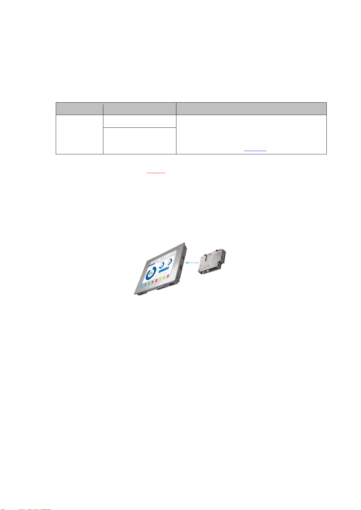
‘Display’ and ‘Box’ of SP5000 series can be separated, so you can freely select a
suitable combination of them according to use. This guidebook introduces
specifications for a combination of SP-5700TP (Premium display) that is a 15-inch
display module and SP-5B00(Standard box) that is a box module.
Safety Information
HAZARD OF OPERATOR INJURY, OR UNINTENDED EQUIPMENT DAMAGE
Before operating any of these products, be sure to read all related manuals
thoroughly.
Failure to follow these instructions can result in death, serious injury or unintended
equipment damage.

Contents
CHAPTER 1 SPECIFICATION COMPARISON 5
1.1. SPECIFICATION OF GP-3750T AND SP-5700TP+SP-5B00 5
CHAPTER 2 COMPATIBILITY OF HARDWARE 7
2.1. LOCATIONS OF CONNECTOR 7
2.2. POWER SUPPLY 9
2.3. USB TRANSFER CABLE 9
2.4. INTERFACE 9
2.4.1. SERIAL INTERFACE 9
2.4.2. AUXILIARY I/O INTERFACE (AUX) 9
2.4.3. SOUND INPUT INTERFACE 10
2.4.4. SOUND OUTPUT INTERFACE 10
2.4.5. CF CARD INTERFACE 10
2.5. PERIPHERAL UNITS AND OPTION UNITS 11
2.5.1. BARCODE/2D [TWO-DIMENSIONAL]CODE READER CONNECTION 11
2.5.2. PRINTER CONNECTION 11
2.5.3. EXPANSION UNIT 11
2.5.4. ISOLATION UNIT 12
2.6. BACKUP BATTERY 12
2.7. SUPPORTED FEATURES 12
2.8. POWER CONSUMPTION 13
2.9. ABOUT PRO-SERVER EX 13
2.10. OTHER NOTES 13
CHAPTER 3 REPLACEMENT PROCEDURE 14
3.1. WORK FLOW 14
3.2. PREPARATION 15
3.3. RECEIVE SCREEN DATA FROM GP3000 SERIES 16
3.4. CHANGE THE DISPLAY UNIT TYPE 20
3.5. TRANSFER THE SCREEN DATA TO SP5000 SERIES 21
3.6. DIFFERENCES OF SOFTWARE 25

Chapter 1 Specification Comparison
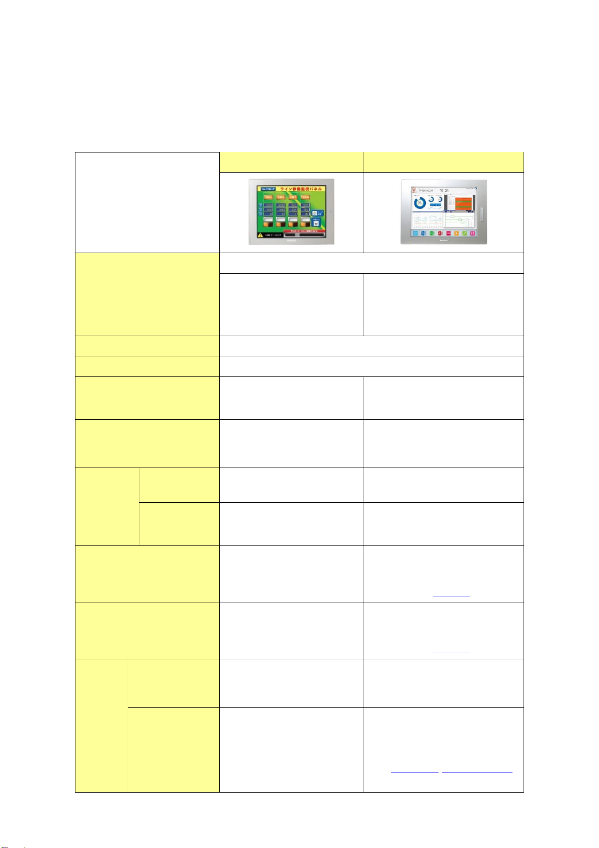
1.1. Specification of GP-3750T and SP-5700TP+SP-5B00
GP-3750T
SP-5700TP+SP-5B00
Display Type
TFT Color LCD
Display Colors
65,536 colors
(without blink)/
16,384 colors
(with blink)
UP!
16,777,216 colors
(without blink) *1
Display Resolution
XGA (1,024×768 pixels)
Panel Cut Dimensions
W383.5×H282.5mm
External Dimensions
W395×H294×D60mm
NEW!
W397×H296×D67mm *2
Touch Panel Type
Resistive film
(Analog)
UP!
Resistive film
(Analog, multi-touch)
Memory
Application
16MB
UP!
64MB
SRAM
SRAM : 320KB
UP!
NVRAM : 320KB
Backup Battery
Secondary Battery
(Rechargeable Lithium
battery)
UP!
-
-> see 2.6
Input Voltage
DC24V
AC 100 to 240V
NEW!
DC 12 to 24V
-> see 2.2
Serial
I/F
COM1
D-Sub9 pin (plug)
RS-232C/422/485
D-Sub9 pin (plug)
RS-232C
COM2
D-Sub9 pin (socket)
RS-422/485
NEW!
D-Sub9 pin (plug)
RS-422/485
-> see 2.4.1 see Chapter 4
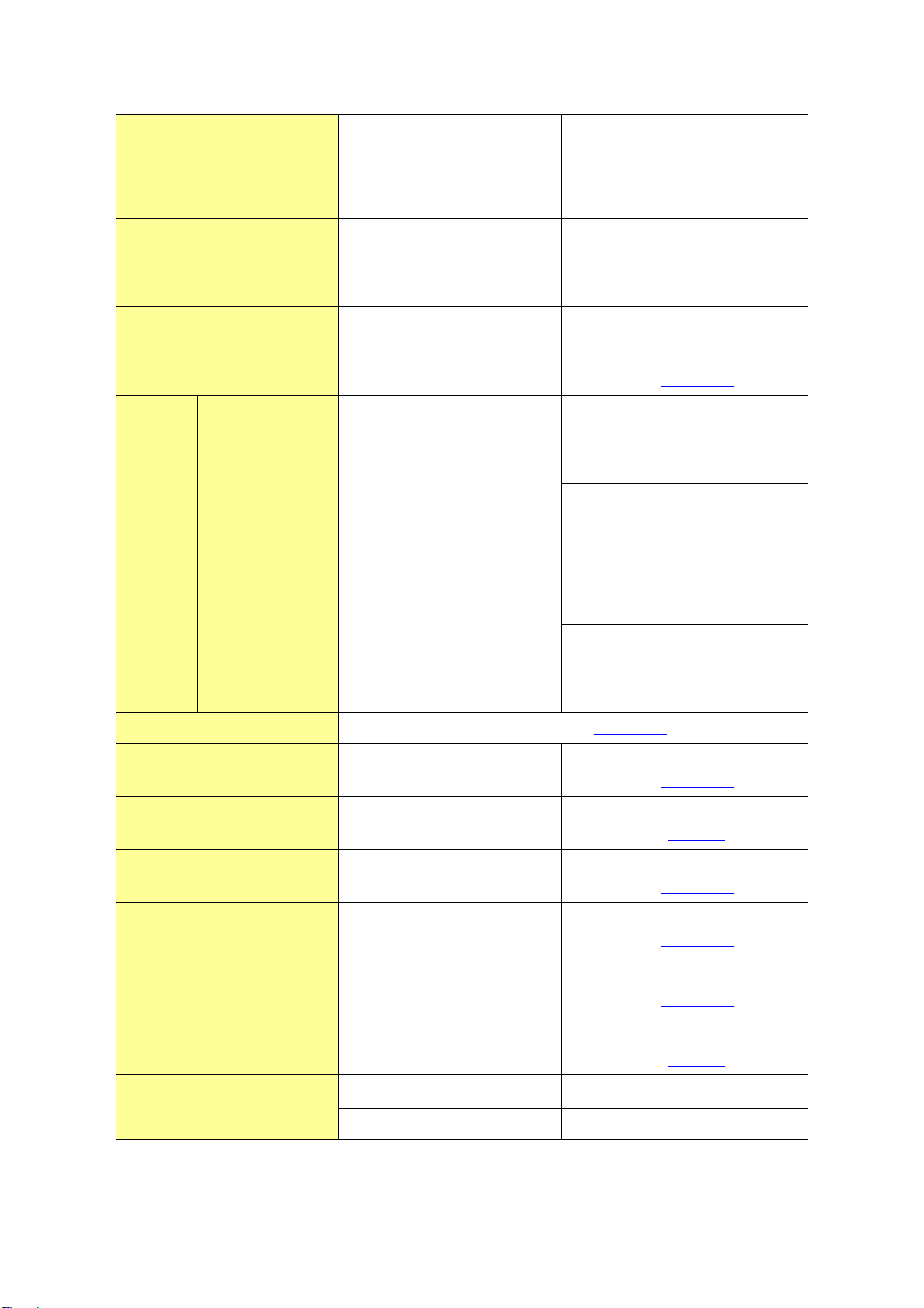
Ethernet I/F
1 port
10BASE-T/100BASE-TX
UP!
2 ports
10BASE-T/100BASE-TX
CF Card I/F
✔
NEW!
-
-> see 2.4.5
SD Card I/F
-
NEW!
✔
-> see 2.4.5
USB
I/F
Type A
2 ports
UP!
SP-5700TP (premium display) :
1 port (Front)
SP-5B00 (Standard box) :
2 ports
Type mini B
-
NEW!
SP-5700TP (premium display) :
1 port (Front)
NEW!
SP-5B00 (Standard box) :
1 port
Printer I/F
USB Type A-> see 2.5.2
Auxiliary I/O I/F
✔
-*3
-> see 2.4.2
Video Input I/F
✔
-
-> see 2.7
Sound Input I/F
✔
-*3
-> see 2.4.3
Sound Output I/F
Speaker output : 70mW
-*3
-> see 2.4.4
Expansion Unit I/F
(Communication Unit)
✔
-*3
-> see 2.5.3
Expansion Unit I/F
(Image Unit)
✔
-
-> see 2.7
Expansion Memory
✔
-*4
Software
GP-Pro EX 2.00 or later
GP-Pro EX 4.08.200 or later
*1: SP-5B00 does not support hardware 3rd speed blink.
*2: Size for the time when SP-5700TP (Premium display) is combined with SP-5B00 (Standard
box).
*3: If need this I/F, SP5B10(Power box) is required.
*4: No expansion unit but SP5000 series has enough memory to cover GP3000 series +
expansion memory.

Chapter 2 Compatibility of Hardware
2.1. Locations of connector
Connector locations of GP-3750T and SP-5700TP+SP-5B00
GP-3750T
SP-5700TP (Premium display)
SP-5B00(Standard box)
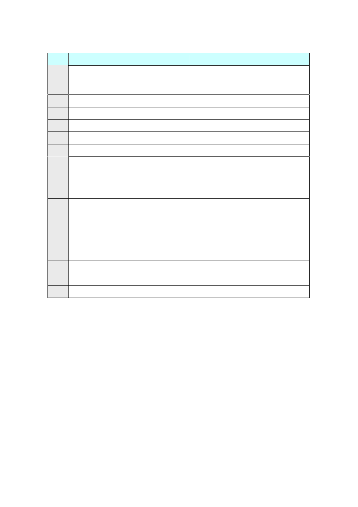
GP-3750T
SP-5700TP+SP-5B00
1
Power Input Terminal Block (AC) /
Power Connector (DC)
Power Connector (DC)
2
Serial I/F (COM1)
3
Serial I/F (COM2)
4
Ethernet I/F
5
USB I/F (Type A)
6
-
USB I/F (Type mini B)
7
-
Storage Card Cover (There’s a SD
card I/F for storage under the cover.)
8
CF card I/F
-
9
Expansion Unit I/F (Communication
Unit)
-
10
Auxiliary I/O / Sound Output I/F
(AUX)
-
11
Expansion Unit I/F
(Image Unit)
-
12
Sound Input I/F
-
13
Video Input I/F
-
14
Expansion Memory Cover
-
2.2. Power supply
SP5000 has a DC power supply type only. When replacing GP-3750T AC type with
SP5000 series, changing to DC power supply is required. For the detailed electric
specifications, see the hardware manual.
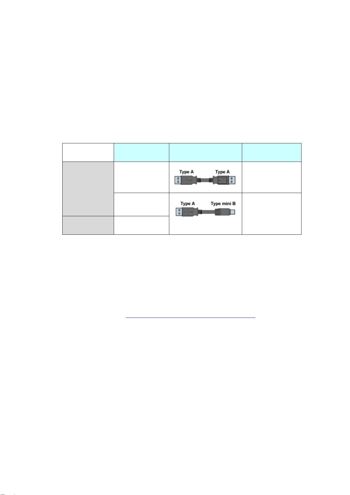
2.3. USB Transfer cable
Like the GP3000 series, a USB transfer cable (CA3-USBCB-01) can be used for the
SP5000 series. Also, a USB (Type mini B) cable (ZC9USCBMB1) and commercial
cables can be used on the SP5000 series’ side.
Model
Connector Type
Connector on
Display
Options
CA3-USBCB-01
USB (Type A)
ZC9USCBMB1
USB (Type mini B)
Commercial
Item
-
2.4. Interface
2.4.1. Serial Interface
The SP5000 series has a COM port on the side of box module.
The pin array and the shapes of the plug and the socket differ between GP-3750T
COM2 port and SP-5B00(Standard box) COM port. The PLC connection cable that
used to be connected to GP3000 Series via its COM2 port cannot be used as it is.
For details, refer to “Chapter 4 Communication with Device/PLC”. Cables other
than that can be used as they are.
When both the COM1 port and the COM2 port have the RS-422/485 setting, only
the COM2 port can be used for RS-422/485 connection after replacement to
SP-5B00(Standard box).
2.4.2. Auxiliary I/O Interface (AUX)
There is no Auxiliary I/O interface (AUX) on SP-5B00(Standard box).
If using AUX, please select SP-5B10(Power box) for the box module.

2.4.3. Sound Input Interface
SP-5B00 (Standard Box) does not have the sound input interface. It’s an
important note especially for those who use sound input with a microphone.
2.4.4. Sound Output Interface
If needed, apply SP5B10(Power box)’s AUX I/F.
The output value has been increased from 70mW to 300mW. Please take note of
it when you use an amplifier.
2.4.5. CF Card Interface
SP5000 series is not equipped with a CF card slot. But a SD card slot and a USB
interfaces are installed. In order to use the GP-3750T data saved in the CF card and
the functions using the CF card, use a SD card or a USB flash drive instead.
When the setting of the output destination folder is set to “CF Card” on GP-Pro EX,
if you change the display unit type, the setting will automatically change to the
one that uses a SD card.
To change the setting of the output destination folder, see [5.1 Changing the
setting of the external media to use].

2.5. Peripheral units and option units
2.5.1. Barcode/ 2D [two-dimensional] code reader connection
Like GP3000 series, SP5000 series allows you to connect a barcode reader to its
USB interface (Type A) or its serial interface. In replacing GP3000 series with
SP5000 series, verify proper operation of the barcode/2D code reader before use.
2.5.2. Printer connection
Like GP3000 series, SP5000 series allows you to connect a printer on its USB
interface (Type A). In replacing GP3000 series with SP5000 series, verify proper
operation of the printer before use.
2.5.3. Expansion Unit
The expansion unit cannot be used with SP-5B00(Standard box).
If you used PROFIBUS unit for GP3000 series (model:CA5-PFSALL/EX-01), please
replace with SP-5B10(Power Box).
In this case, apply PROFIBUS DP Slave (model no.: PFXZCDEUPF1) for
SP-5B10(Power box)
Reference:
[FA315627] Replacement for GP3000 series PROFIBUS unit (Model no.:
CA5-PFSALL/EX-01)
https://www.proface.com/en/support/faq?page=content&country=PROFACE&la
ng=en&locale=en_US&id=FA315627&prd=&redirect=true
SP5000 Series Option List
(https://www.proface.com/en/product/hmi/sp5000/option)
The expansion unit (each kind of unit like CC-LINK Unit, VM unit) for GP3000
series cannot be used for SP5000 series.
2.5.4. Isolation Unit
RS-485 isolation unit for GP3000 Series (CA3-ISO485-01) cannot be used for
SP-5B00(Standard box). You can use the RS-232C isolation unit
(CA3-ISO232-01) for SP-5B00 (Standard box) instead. (The communication
method is switched with this unit’s DIP switch.)
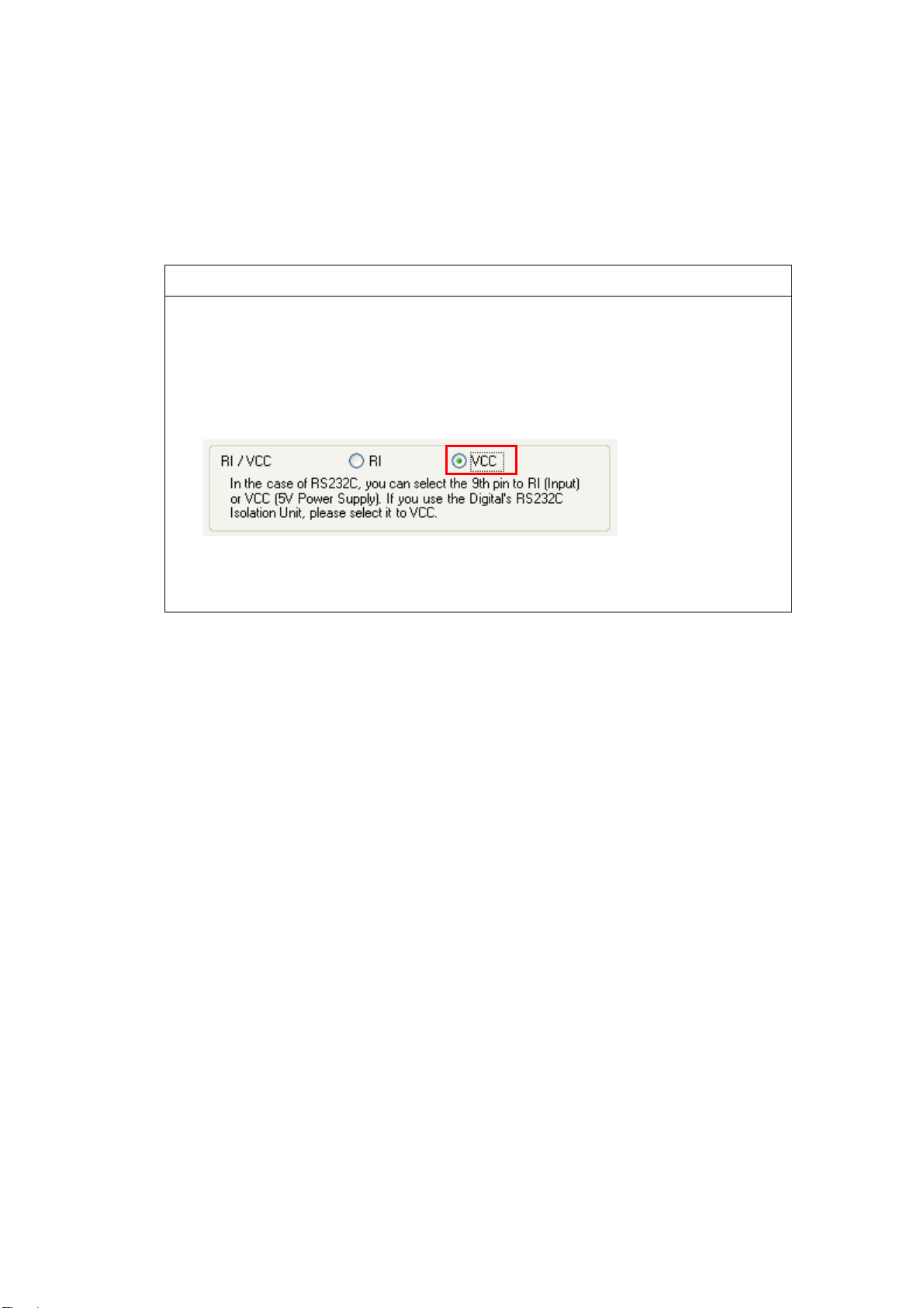
Note for using RS-232C isolation unit (CA3-ISO232-01)
・Connect it to SP5000 series via COM1 (232C).
・In the case of RS-232C, it’s necessary to set the 9th pin of the COM port to
VCC.
[Settings on GP-ProEX]
Select “VCC” from [System Settings] -> [Device/PLC] in the [Project] menu
on GP-Pro EX.
・RS-422/485 (2-wire type) communication and serial multilink are not
supported.
2.6. Backup Battery
SP-5B00 is not needed a backup battery for Clock.
Supercapacitor (electric double-layer capacitor) can be back up clock data.
Please note the following points,
When the voltage from the Supercapacitor is low, clock data is lost when this
product is turned OFF. In order to charge up the super capacitor, power
needs to be supplied to the main unit for 5 minutes or longer.
The average period for backup is as follows:
Initial: Approximately 100 days
After 5 years: Approximately 30 days (used at ambient temperature of 25 °C [77 °F])
By connecting the Battery for Memory Backup (Model Number PFXZCBBT1)
accessory, you can set up a backup period of up to 10 years or more.
2.7. Supported features
SP5000 Series does not support the following features.
Recording/Playing a video
Features using Image Unit (VM/DVI/RGB input)
Camera-Viewer EX
RPA
PLC Ladder Monitor

2.8. Power Consumption
The power consumption of GP3000 series is different from that of SP5000 series.
GP-3750T
ST-5700TP+SP-5B00
50W or less
40W or less
2.9. About Pro-Server EX
Use Pro-Server EX Ver.1.36 or later. For more detail, please refer to the following.
(http://www.proface.co.jp/otasuke/qa/server_ex/replace/)
2.10. Other Notes
Do not expose SP5000 series to direct sunlight.
Do not use SP5000 series outdoors.
Do not turn on SP5000 series if condensation has occurred inside the device.
When you are continuously using SP5000 series without oxygen, the
brightness might decrease. Please ventilate the control panel periodically.

Chapter 3 Replacement Procedure
3.1. Work Flow
Installation
Screen
Communication
Check the compatibility of
hardware in Chapter 2.
Receive screen data from
GP3000 Series. *1
Remove GP3000 Series.
Install SP5000 series.
Connect the power cord.
Check the performance
and start operation.
Change the received data
on GP-Pro EX.
Check and modify the
data on GP-Pro EX.
Transfer the screen data
to SP5000 series.
Check the connection
between SP5000 series
and a PLC in the GP-Pro
EX Device/PLC
Connection Manual.
Connect SP5000 series
and PLC with the PLC’s
cable.
Start connection and
check the communi-
cation.
*1: This step is required if screen data is saved only in the GP unit, not in any other device.
When replacing GP3000
series to SP5000 series
process the panel.

15 / 29
3.2. Preparation
Requirements for
receiving screen data
from GP3000 Series*1
PC in which GP-Pro EX Transfer Tool is installed. *2
USB Transfer Cable (model: CA3-USBCB-01)
* Possible to send/receive a screen via a CF card, a USB
storage device or Ethernet.
Requirements for
converting screen data
of GP3000 Series and
transferring the
converted data to
SP5000 series.
PC with GP-Pro EX installed.
Ver4.08.200 or later is required for SP-5B00.
Transfer Cable (The following three types of cables are
available)
・A USB transfer cable (model: CA3-USBCB-01)
・A USB data-transfer cable (model: ZC9USCBMB1)
・A commercial USB cable (USB Type A/mini B)
* Possible to send/receive a screen via a SD card , a USB
storage device or Ethernet.
*1: This step is required if screen data is saved only in the GP unit, not in any other device.
*2: Please use the same version or later as or than that of the software used during creating screens on
GP3000 Series. If you don’t know the version, we recommend you to use the newest version. For the
newest version, you can download the transfer tool from our web site called [OtasukePro!]
(http://www.pro-face.com/otasuke/download/freesoft/gpproex_transfer.htm).

16 / 29
3.3. Receive screen data from GP3000 series
You can transfer data to GP3000 Series via;
A USB transfer cable (model: CA3-USBCB-01)
A CF card/USB storage device
Ethernet
If you have backed up screen data, this step is unnecessary, skip to the next
section [3.4 Change the Display Unit Type].
(1) Connect your PC and GP3000 Series with a USB transfer cable.
If the driver of the cable has not been installed on your PC yet, a dialog
box will appear. Please follow the instructions.
NOTE
The “Hardware Installation” dialog box as shown below may appear
during installing the USB driver depending on the security level of
Windows®. Click [Continue Anyway] to start installing the driver. When
installation is completed, click [Finish].
17 / 29
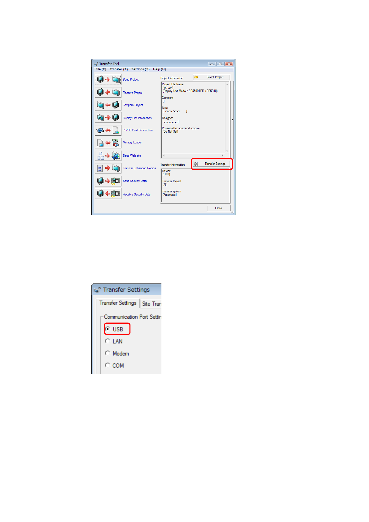
(2) Start the Transfer Tool of GP-Pro EX.
(3) Make sure that the [Device] in the “Transfer Settings Information” is set
to [USB].
If not, click the [Transfer Setting] button to open the “Transfer Setting”
dialog box.
Select [USB] in the Communication Port Settings field and click [OK].
18 / 29
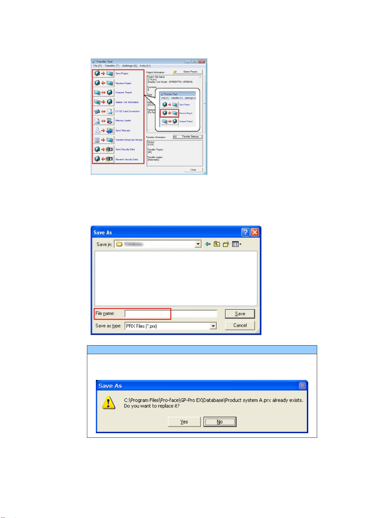
(4) Start GP-Pro EX Transfer Tool and click the [Receive Project] button
(5) Click [Receive Project], and the following dialog box will appear. Specify a
place to save the received data in and a project file name, and then click
[Save] to start transfer.
NOTE
When a file exists, the window that confirms whether or not to overwrite
the file is displayed.
19 / 29
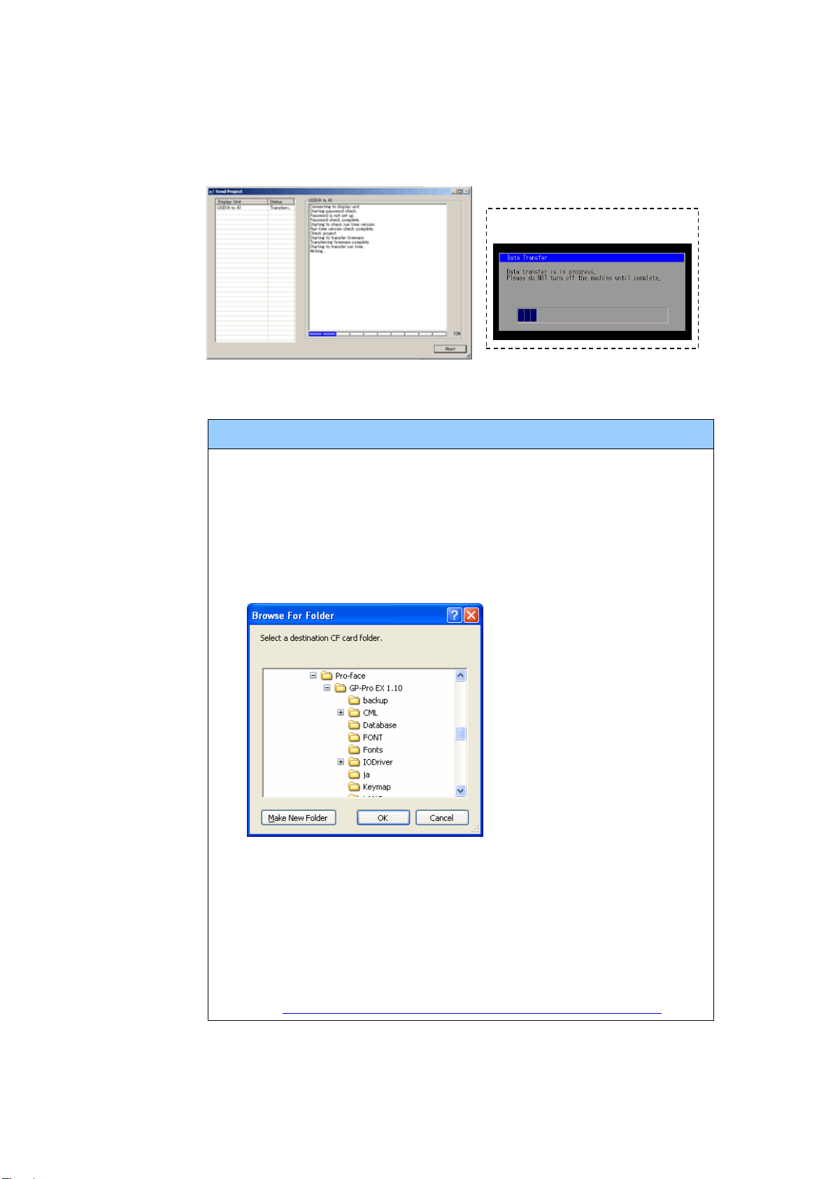
(6) The following dialog box appears during transfer and you can check the
communication status. (The display unit enters the Transferring mode
and communication with the device such as a PLC is terminated.)
NOTE
(1) If you receive the project files that use CF card data such as Recipe
Function (CSV data), the following dialog box will appear during
transfer. Specify a place to save the CF card data in. Click [OK],
and the [Receive Project] dialog box will return and transfer will be
completed.
(2) SP5000 series that is a replacement model is not equipped with a
CF card slot. If the display unit type is changed to SP5000 series,
the CF card setting will be replaced with the SD card setting
automatically. To check or change the destination folder setting,
see [5.1 Changing the setting of the external media to use].
Display Screen
20 / 29
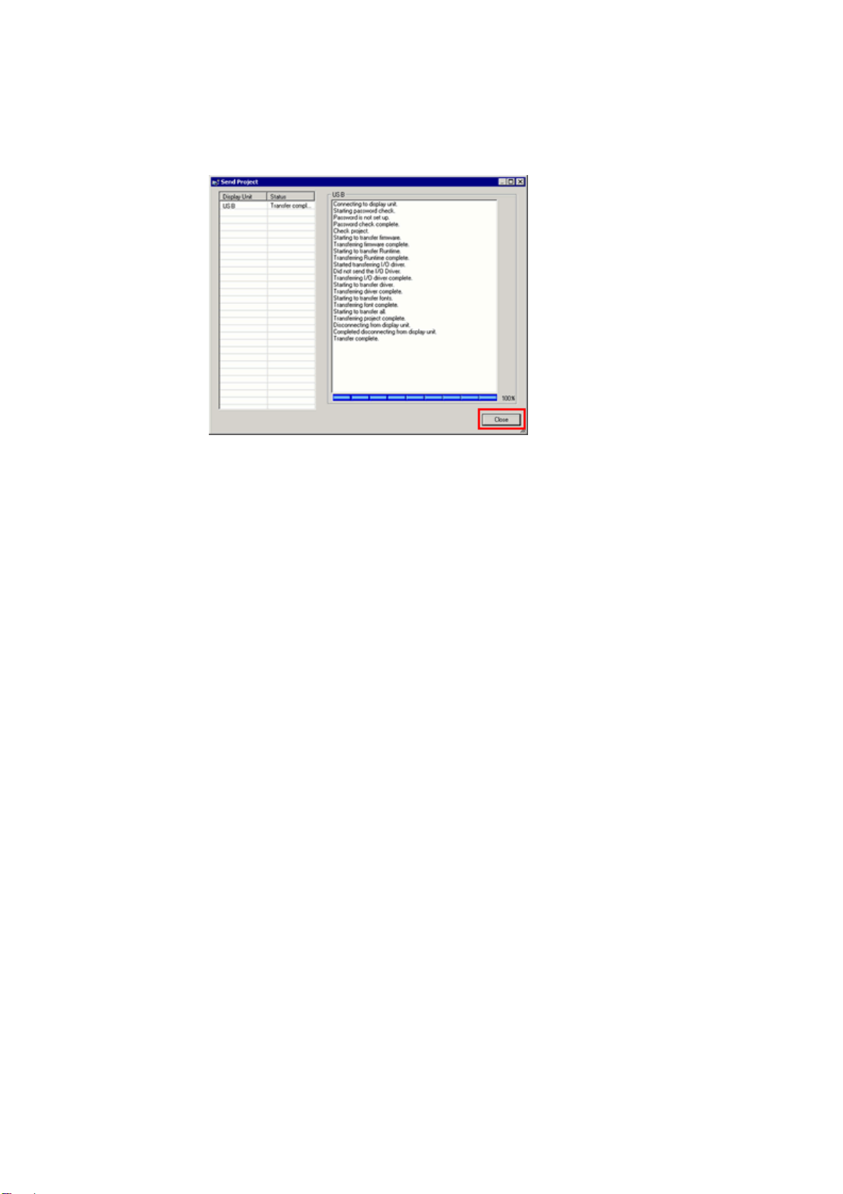
(7) When transfer is completed, the status displayed in the dialog box will
change from [Transferring] to [Complete Transfer]. Click [Close] to close
the dialog box.
(8) Close the Transfer Tool.
3.4. Change the Display Unit Type
Open the received project file (*.prx) of GP3000 Series on GP-Pro EX and change
the display unit type to SP5000 series.
(1) Open the received project file (*.prx) on GP-Pro EX.
(2) Click [System Settings]->[Display]->[Change Display] in [Project] menu and
change the Display Unit type to the replacement model.
(3) Click [Project]->[Save As] and save the changed project file.
This manual suits for next models
4
Other Pro-face Monitor manuals

Pro-face
Pro-face SP5000 Series User manual

Pro-face
Pro-face GP-4201TM User manual

Pro-face
Pro-face GP-4000M User manual

Pro-face
Pro-face GP577R-TC11 User manual

Pro-face
Pro-face GP77R Series Instruction manual

Pro-face
Pro-face FP-790T User manual

Pro-face
Pro-face FP2650-T41 User manual

Pro-face
Pro-face GC4000 Series User manual

Pro-face
Pro-face GP-3300T Manual

Pro-face
Pro-face Xycom SXT1811 Installation instructions


