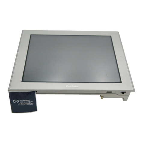
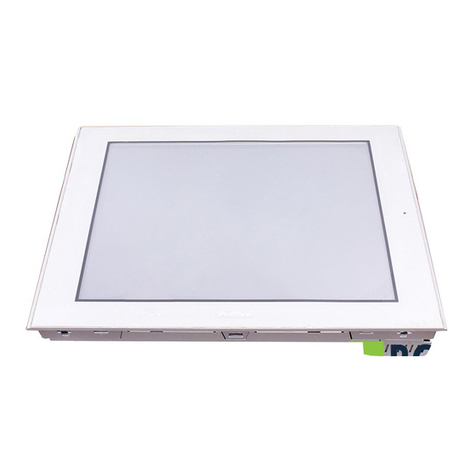
Pro-face SP-5600TP User manual

SP5000 Series (Display Module)
Installation Guide

3
English
Safety Information
Important Information .......................................................................................5
Model Numbers
Model Numbers ...............................................................................................7
Overview
Package Contents............................................................................................8
About the Manual .............................................................................................9
Global Code .....................................................................................................9
Part Numbers and Functions
SP-5500TP ....................................................................................................10
SP-5600TP/5660TP ......................................................................................11
SP-5700TP ....................................................................................................12
SP-5400WA ..................................................................................................13
SP-5500WA ..................................................................................................14
SP-5600WA ..................................................................................................15
LED Indications ..............................................................................................16
Specifications
Electrical Specifications .................................................................................17
Environmental Specifications .........................................................................19
Installation
Panel Cut Dimensions....................................................................................20
Installation Requirements...............................................................................21
Installation Procedure ....................................................................................27
Removal Procedure .......................................................................................31
Wiring
Wiring .............................................................................................................34
Front USB Cover
Front USB Cover............................................................................................41
Please read the “Warning/Caution Information” on the attached
sheet before using the product.

4
English
Front USB Port
Front USB Port............................................................................................... 43
Standards
Standards....................................................................................................... 46

5
English
Safety Information
Important Information
Notice
Read these instructions carefully, and look at the equipment to become
familiar with the device before trying to install, operate, or maintain it. The
following special messages may appear throughout this documentation or on
the equipment to warn of potential hazards or to call attention to information
that clarifies or simplifies a procedure.

6
English
Safety Information
PLEASE NOTE
Electrical equipment should be installed, operated, serviced, and maintained
only by qualified personnel. No responsibility is assumed by Pro-face for any
consequences arising out of the use of this material.
A qualified person is one who has skills and knowledge related to the
construction and operation of electrical equipment and its installation, and has
received safety training to recognize and avoid the hazards involved.

7
English
Model Numbers
Model Numbers
NOTE: These models can be connected to all models of SP5000 Series Box Module. For
the model numbers of the Box Module, refer to the SP5000 Series (Box Module) Installation
Guide.
Series Model name Model number
SP5000 Series Premium Display SP-5500TP PFXSP5500TPD
SP-5600TP PFXSP5600TPD
SP-5660TP PFXSP5660TPD
SP-5700TP PFXSP5700TPD
Advanced Display SP-5400WA PFXSP5400WAD
SP-5500WA PFXSP5500WAD
SP-5600WA PFXSP5600WAD

8
English
Overview
Package Contents
The following items are included in the package. Before using this product,
please confirm that all items listed here are present.
1SP5000 Series Display Module: 1
2Installation gasket: 1 (attached to this product)
3DC power supply connector (right-angle type*1): 1
4SP5000 Series (Display Module) Installation Guide (this guide): 1
5Warning/Caution Information: 1
*1 Straight type for SP-5400WA
This product has been carefully packed, with special attention to quality.
However, should you find anything damaged or missing, please contact your
local distributor immediately.

9
Overview
English
About the Manual
This manual describes wiring and installation procedures. For more detailed
information, refer to the SP5000 Series Hardware Manual.
You can download the manual from our website “Otasuke Pro!” at
http://www.pro-face.com/trans/en/manual/1001.html
Global Code
A global code is assigned to every Pro-face product as a universal model
number.
For more information on product models and their matching global codes,
please refer to the following URL.
http://www.pro-face.com/trans/en/manual/1003.html

10
English
Part Numbers and Functions
SP-5500TP
A: Brightness sensor
B: Front USB cover
C: USB (Type A) interface
D: USB (mini-B) interface
E: Status LED (see page 16)
F: Power plug connector
Front
Rear

11
Part Numbers and Functions
English
SP-5600TP/5660TP
A: Wireless LAN antenna (only for SP-5660TP)
B: Brightness sensor
C: Front USB Cover
D: USB (Type A) interface
E: USB (mini-B) interface
F: Status LED (see page 16)
G: Power plug connector
Front
Rear

12
English
Part Numbers and Functions
SP-5700TP
A: Brightness sensor
B: Front USB cover
C: USB (Type A) interface
D: USB (mini-B) interface
E: Status LED (see page 16)
F: Power plug connector
Front
Rear

13
Part Numbers and Functions
English
SP-5400WA
A: Status LED (see page 16)
B: Power plug connector
Front
Rear

14
English
Part Numbers and Functions
SP-5500WA
A: Status LED (see page 16)
B: Power plug connector
Front
Rear

15
Part Numbers and Functions
English
SP-5600WA
A: Status LED (see page 16)
B: Power plug connector
Front
Rear

16
English
Part Numbers and Functions
LED Indications
Status LED
*1 Only when your screen editing software supports the Logic Program.
*2 Make sure your screen editing software supports the function.
NOTE: When Open Box is connected, even if its operating system is shut down, the status
LED on the Display Module will display red if connected to a power supply.
Color Indicator
Connected to Power Box
Connected to Open Box
HMI
Operation
Logic
Program
Operation*1
HMI
Operation
Logic
Program
Operation*1
Green ON Offline – Offline –
In
operation
RUN In
operation
RUN
Flashing*1 In
operation
STOP In
operation
STOP
LED
fade*2
Backlight OFF (Standby Mode)
Orange Flashing Software starting up
Red ON Power is ON.
Flashing*1 In
operation
Major error In
operation
Major error
Red/
Green
Alternating Box Module connection error
Orange/
Red
Alternating SD Card boot error –
Orange/
Red/
Green
Alternating Display Module internal error
– OFF Power is OFF.

17
English
Specifications
Electrical Specifications
SP-5500TP/5600TP/5660TP/5700TP
*1 The power consumption for the combined unit of Box Module and Display Module equals
the sum of the power consumption for the Modules.
Specification
SP-5500TP SP-5600TP SP-5660TP SP-5700TP
Power supply
Rated input voltage 12...24 Vdc
Input voltage limits 10.8...28.8 Vdc
Voltage drop 12 Vdc: 1.25 ms or less
24 Vdc: 5 ms or less
Power consumption
(primary power supply
including power loss)
Max (including
Box Module)
50W56W58W57W
Max (Display
Module only)*1
15W21W23W22W
When power is
not supplied to
external
devices
(Display
Module only)*1
12 W or
less
18 W or
less
20 W or
less
19 W or
less
When screen
turns off the
backlight
(Stand-by
Mode) (Display
Module only)*1
6 W or less 8 W or
less
6 W or
less
When screen
backlight 20%
(Display
Module only)*1
8 W or
less
11 W or
less
13 W or
less
11 W or
less
In-rush current 30 A or less
Voltage endurance 1,000 Vac, 20 mA for 1 minute (between
charging and FG terminals)
Insulation resistance 500 Vdc, 10 MΩor more (between charging
and FG terminals)

18
English
Specifications
SP-5400WA/5500WA/5600WA
*1 The power consumption for the combined unit of Box Module and Display Module equals
the sum of the power consumption for each of the Modules.
Specification
SP-5400WA SP-5500WA SP-5600WA
Power supply
Rated input voltage 12...24 Vdc
Input voltage limits 10.8...28.8 Vdc
Voltage drop 12 Vdc: 1.25 ms or less
24 Vdc: 5 ms or less
Power consumption
(primary power supply
including power loss)
Max (including Box
Module)
41 W 43 W 45 W
Max (Display
Module only)*1
6.5 W 8.5 W 11.5 W
When power is not
supplied to external
devices (Display
Module only)*1
–
When screen turns
off the backlight
(Stand-by Mode)
(Display Module
only)*1
2 W or less 2.5 W or less 2.5 W or less
When screen
backlight 20%
(Display Module
only)*1
4 W or less 5 W or less 6 W or less
In-rush current 30 A or less
Voltage endurance 1,000 Vac, 20 mA for 1 minute (between
charging and FG terminals)
Insulation resistance 500 Vdc, 10 MΩor more (between
charging and FG terminals)

19
Specifications
English
Environmental Specifications
NOTE: When using any of the options for this product, check the specifications for special
conditions or cautions that may apply to this product.
Physical environment
Surrounding air
temperature
0...60 °C (32...140 °F)
Storage temperature -20...60 °C (-4...140 °F)
Surrounding air and
storage humidity
10...90% RH (non-condensing, wet bulb
temperature 39 °C [102.2 °F] or less)
Dust 0.1 mg/m3(10-7 oz/ft3) or less (non-conductive
levels)
Pollution degree For use in Pollution Degree 2 environment

20
English
Installation
Panel Cut Dimensions
Based on the panel cut dimensions, open a mount hole on the panel.
Model name A B C
SP-5500TP 259 mm
(10.2 in)
201 mm
(7.91 in)
1.6... 5 mm
(0.06... 0.2 in)
SP-5600TP/
5660TP 301.5 mm
(11.87 in)
227.5 mm
(8.96 in)
SP-5700TP 383.5 mm
(15.1 in)
282.5 mm
(11.12 in)
SP-5400WA 190 mm
(7.48 in)
135 mm
(5.31 in)
SP-5500WA 255 mm
(10.04 in)
185 mm
(7.28 in)
SP-5600WA 295 mm
(11.61 in)
217 mm
(8.54 in)
+1
-0
+0.04
-0
+1
-0
+0.04
-0
+1
-0
+0.04
-0
+1
-0
+0.04
-0
+1
-0
+0.04
-0
+1
-0
+0.04
-0
+1
-0
+0.04
-0
+1
-0
+0.04
-0
+1
-0
+0.04
-0
+1
-0
+0.04
-0
+1
-0
+0.04
-0
+1
-0
+0.04
-0

21
Installation
English
Installation Requirements
This product is designed for use on flat surfaces of Type 1, Type 4X (Indoor
Use Only) or Type 13 Enclosure.
Mount this product in an enclosure that provides a clean, dry, robust and
controlled environment (IP65F*1, IP66F*1, IP67F*1, Type 1, Type 4X [Indoor
Use Only], or Type 13 Enclosure).
For Advanced Display, the front surface is IP66F*1, IP67F*1, Type 1, Type 4X
(Indoor Use Only) or Type 13 Enclosure.
For Premium Display, when using a factory-installed front USB cover (without
screw), the front surface is IP65F*1, IP67F*1 or Type 1 Enclosure. When using
a front USB cover (with screw*2) manufactured by Pro-face (Model Number
PFXZCDCVUS1), the front surface is IP66F*1, IP67F*1, Type 1, Type 4X
(Indoor Use Only) or Type 13 Enclosure.
For Premium Display, regardless of using a factory-installed front USB cover
or a front USB cover with screw, when the cover is open, the front surface is
Type 1 Enclosure.
Be aware of the following when building this product into an end-use product:
• The rear face of this product is not approved as an enclosure. When building this
product into an end-use product, be sure to use an enclosure that satisfies
standards as the end-use product’s overall enclosure.
• Install this product in an enclosure with mechanical rigidity.
• This product is not designed for outdoor use. UL certification obtained is for
indoor use only.
• Install and operate this product with its front panel facing outward.
*1 IP65F, IP66F and IP67F are not part of the UL certification.
*2 The necessary torque is 0.5 N•m (4.4 lb-in).
Display front surface Enclosure front
surface
Premium Display Advanced Display
Without
screw
With screw
IP65F, IP67F,
Type 1
IP66F, IP67F,
Type 1, Type 4X
(Indoor Use
Only), Type 13
IP66F, IP67F,
Type 1, Type 4X
(Indoor Use Only),
Type 13
IP65F, IP66F,
IP67F,
Type 1, Type 4X
(Indoor Use Only),
Type 13
This manual suits for next models
6
Table of contents
Other Pro-face Monitor manuals
Pro-face
Pro-face GC4000 Series User manual
Pro-face
Pro-face GP577R-TC11 User manual
Pro-face
Pro-face FP3650-T41 User manual
Pro-face
Pro-face PS-3000B Series User manual
Pro-face
Pro-face Xycom SXT1811 Installation instructions
Pro-face
Pro-face GP-3300T Manual
Pro-face
Pro-face GP-4000M User manual

Pro-face
Pro-face SP5000 Series User manual
Pro-face
Pro-face FP-790T User manual
Pro-face
Pro-face GP-4201TM User manual

