Pro-face FP-790T User manual

Flat Panel Display
FP-790T
User Manual
Digital Electronics Corporation

FP-790T User Manual 1
1) It is forbidden to copy the contents of this manual, in whole or in part, except for the
user's personal use, without the express permission of the Digital Electronics Corporation
of Japan.
2) The information provided in this manual is subject to change without notice.
3) This manual has been written with care and attention to detail; however, should you find
any errors or omissions, please contact the Digital Electronics Corporation and inform
them of your findings.
4) Please be aware that the Digital Electronics Corporation is not responsible for any dam-
ages resulting from the use of our products, regardless of article 3 above.
<Note>
Thank you for purchasing Digital's TFT type color display panel, the 'FP-790T'(hereafter referred
to as "the FP").
The FP is a TFT type color liquid crystal display monitor for Windowscompatible personal
computers (VGA, XGA and SVGA modes).
Please read this manual completely to insure the correct use and complete understanding of the
FP's functions.
The FP's analog interface is designed to comply with VESA standards. Please be aware that this
unit may not be able to be connected with devices using nonstandard VGA interfaces. For
further information, please refer to this chapter's "PC Connection Notes" section.
Preface
All Company/Manufacturer names used in this manual are the registered trademarks of their
respective companies.
© Copyright 2001 Digital Electronics Corporation
FP-790T User Manual2
• To avoid the possiblity of an electric shock, be sure to connect the power
cord to the FP before connecting it to the main power supply.
• A fire or electrical shock may occur if voltages used with the FP are beyond
the specified range. Be sure to use only the specified voltage.
• Before opening the FP's protective cover, be sure to turn the units power
OFF. This is because the FP's internal parts carry high voltages.
• To avoid fires or electrical hazards, do not modify the FP in any way.
• Do not create touch panel switches that are used to either control or to
ensure the safety of equipment and personnel. Mechanical switches, such
as an emergency stop switch, a deadman (two-handed) start switch, etc.,
must be installed and operated via a separate control system.
• Do not create touch panel switches which could possibly endanger the safety
of humans and equipment. This is due to the possibility of a malfunction in
the FP or its cable(s), causing the output of a signal that could result in a
major accident. All of a system’s major, safety-related switches should be
designed to be operated separately from the FP.
This section describes the safety precautions necessary for the correct use of the FP.
Please keep this manual close at hand and refer to it when necessary.
Safety Icons
The following symbols are used throughout this manual to ensure the safe use of the
FP. Please be sure to follow all instructions given since they explain important safety
points.
Essential Safety Precautions
This mark warns of a situation that could cause
either serious or fatal injury if the instruction is
ignored and/or the unit is used incorrectly.
This mark warns of a situation that could cause
either personal injury or property damage if the
instruction is ignored and/or the unit is used
incorrectly.
Warning
Cautions
WARNINGS

FP-790T User Manual 3
WARNINGS
• After the FP's backlight burns out, unlike the FP's "Standby Mode", the touch
panel is still active. If the operator fails to notice that the backlight is burned
out and touches the panel, a potentially dangerous machine operation
mistake can occur.
If your FP's backlight suddenly turns OFF, use the following steps to
determine if the backlight is actually burned out.
1)If your FP is not set to "Standby Mode" and the screen has gone blank,
your backlight is burned out.
2)Or, if your FP is set to Standby Mode, but touching the screen does not
cause the display to reappear, your backlight is burned out.
• If metal particles, water or other types of liquids contact any of the FP's
internal parts, immediately turn the units power OFF, unplug the power cord,
and contact either your FP distributor or the Digital Electronics Corporation.
• Read and understand Chapter 3 "Installation and Wiring" thoroughly in order
to select an appropriate installation location for the FP.
• Before either plugging in or unplugging a board or interface connector, be
sure to turn the FP's power OFF.
• To prevent a possible explosion, do not install the FP in areas containing
flammable gases.
• The FP is not appropriate for use with aircraft control devices, aerospace
equipment, central trunk data transmission (communication) devices, nuclear
power control devices, or medical life support equipment, due to these
devices inherent requirements of extremely high levels of safety and
reliability.
• When using the FP with transportation vehicles (trains, cars and ships),
disaster and crime prevention devices, various types of safety equipment,
non-life support related medical devices, etc. redundant and/or failsafe
system designs should be used to ensure the proper degree of reliability
and safety.
FP-790T User Manual4
About the FP's Display Panel
•The FP's currently displayed data, its voltage and brightness setting each affect the intensity
of Contouring. (i.e, when some parts of the screen are brighter than others, creating a
wavelike pattern)
•There are minute grid-points (dark and light) on the Display Panel's surface. This is part of
the FP's design and not a defect.
•Shadows may appear at the top of the LCD. This is normal for an LCD display.
•Sometimes the display area may look as if the display colors have changed. This is a
common attribute of LCD's and is not a defect.
•Displaying a single image for long periods can cause an afterimage to remain when the
display is changed to another screen. To prevent this, periodically turn the FP OFF and
then ON again to remove this afterimage.
• Do not push on the FP’s screen too strongly, with either your finger or with a
hard object. Excessive pressure can scratch, crack or damage the screen.
• Do not use a pointed object, such as a mechanical pencil or screw-driver, to
press any of the touch panel’s switches, since they can damage the display.
• If the screen becomes dirty or smudged, moisten a soft cloth with diluted
neutral detergent, wring the cloth well, and wipe the display. Do not use thin-
ner or organic solvents.
• Avoid exposing the FP to, or operating the FP in direct sunlight, high tem-
peratures and humidity, and in areas where excessive dust and vibration will
occur.
• Avoid using the FP in areas where sudden, extreme changes in temperature
can occur. This may cause con-densation to form inside the unit, possibly
leading to an accident.
• To prevent the FP from overheating, be sure its air circulation vents are clear
and clean, and keep the unit’s operation area well-ventilated.
• Avoid operating or storing the FP near chemicals, or where chemicals can
come into contact with the unit.
CAUTIONS

FP-790T User Manual 5
Table of Contents
Preface ...................................................................................................................................... 1
Essential Safety Precautions ............................................................................................................ 2
Table of Contents .............................................................................................................................. 5
CE Marking Notes ............................................................................................................................ 7
PC Connection Notes ........................................................................................................................ 7
FP-790T Features.............................................................................................................................. 8
Package Contents .............................................................................................................................. 9
Symbol Information........................................................................................................................ 10
Chapter 1—Introduction
1-1 Connecting the FP to a PC .....................................................................................................1-1
1-2 Optional Equipment ...............................................................................................................1-3
Chapter 2—Specifications
2-1 General Specifications ............................................................................................................2-1
2-1-1 Electrical Specifications.................................................................................................2-1
2-1-2 Structural Specifications ................................................................................................2-1
2-1-3 Environment Specifications ...........................................................................................2-2
2-1-4 Touch Panel Specifications ............................................................................................2-2
2-1-5 External Interface Specifications ...................................................................................2-3
2-2 Functional Specifications .......................................................................................................2-3
2-2-1 Display Specifications....................................................................................................2-3
2-3 Interface Specifications ..........................................................................................................2-4
2-3-1 Analog RGB Interface....................................................................................................2-4
2-3-2 RS-232C Interface ..........................................................................................................2-5
2-3-3 Mouse Connector ...........................................................................................................2-6
2-3-4 Mouse Type Host Connector..........................................................................................2-6
2-4 Option Cable Pin Diagrams...................................................................................................2-7
2-5 Parts Names and Functions ..................................................................................................2-9
2-6 Dimensions ...........................................................................................................................2-10
2-6-1 FP-790T External Dimensions .....................................................................................2-10
2-6-2 Installation Fasteners....................................................................................................2-11
2-6-3 Panel Cut Dimensions ..................................................................................................2-10

FP-790T User Manual6
Chapter 3—Installation and Wiring
3-1 Installation ...............................................................................................................................3-1
3-1-1 Installation Procedures ...................................................................................................3-1
3-2 Wiring ...................................................................................................................................3-4
3-2-1 Power Cable Connection Precautions ............................................................................3-4
3-2-2 FP Power Cable Connection Procedures .......................................................................3-6
3-2-3 FP Power Supply Connection Procedures .....................................................................3-7
3-2-4 FP Grounding Cautions ..................................................................................................3-7
3-2-5 FP Input/Output Signal Line Cautions...........................................................................3-7
3-3 Setup of Operation Mode and Positioning of Display.........................................................3-8
3-3-1 Operation Mode Setup and Adjustment.........................................................................3-8
3-4 Screen Adjustment using OSD ............................................................................................3-10
Chapter 4—Touch Panel Commands
4-1 Command List .........................................................................................................................4-1
4-2 Touch Panel Data Input..........................................................................................................4-3
4-3 Boot-up Initialization..............................................................................................................4-7
Chapter 5—Troubleshooting
5-1 Troubleshooting.......................................................................................................................5-1
5-1-1 Possible Device Problems ..............................................................................................5-1
5-1-2 No Display......................................................................................................................5-2
5-1-3 The Touch Panel Does Not Function .............................................................................5-4
Chapter 6—Maintenance
6-1 Cleaning the FP's Display ......................................................................................................6-1
6-2 Periodic Check-Up ..................................................................................................................6-2
6-3 Changing the Backlight ..........................................................................................................6-3

FP-790T User Manual 7
CE Marking Notes
The FP's analog RGB interface offers normal display performance within the
following ranges:
Since some commercially-available video interface equipment also accomodates
tracking ranges in excess of those shown above, they may not offer normal display
performance when used with the PC. Before using a video interface, be sure to
check its specifications.
Also, even if the same type personal computer is used to transfer data to the PC,
the above mentioned problems can also occur when the PC's video board is
replaced.
While the FP('s OS) is starting up, please do not touch the screen's touch panel.
PC Connection Notes
VESA standard
displaymode Size Horizontal
frequency Vertical
frequency Dot clock
frequency SyncLogic
V.H
31.469kHz 59.992Hz 25.175MHz -,-
37.500kHz 75.000Hz 31.500MHz -,-
37.879kHz 60.317Hz 40.000MHz +,+
46.875kHz 75.000Hz 49.500MHz +,+
48.363kHz 60.004Hz 65.000MHz -,-
56.476kHz 70.069Hz 75.000MHz +,+
60.023kHz 75.029Hz 78.750MHz +,+
31.469kHz 70.087Hz 28.322MHz +,-
37.927kHz 85.039Hz 35.500MHz +,-
640×480
800×600
1024×768
720×400
VGA
SVGA
XGA
USText
The FP-790T is a CE marked, EC compliant product.
<Complies with the following Standards>
Safety (EN60950)
EMI (EN55011 class A), EN61000-3-2, EN61000-3-3
EMS (EN61000-6-2)
• The allowable frequency fluctuation range in both the horizontal
and vertical frequencies is +/- 1%. If fluctuations exceed these
ranges, the FP will enter power save mode and the display will go
blank.
• Be sure to turn FP-790T and PC ON at the same time, or before
turning PC ON. If PC is turned ON first, a touch panel and an exter-
nal mouse will not work.

FP-790T User Manual8
•Large-sized, high-quality color LCD
The monitor uses a 14.1 inch TFT type color LCD, and the 260,000 display colors
allow a wide variety of screen designs. The features of this display are easy-to-
read images and text, wide view angle, high contrast, and fast response.
•FP's large-sized display is XGA mode compatible
The FP is compatible with XGA mode, allowing a large variety of information to
be displayed.
•Display mode is automatically selected (Multi-scan)
The FP's multi-scan feature automatically selects the display mode, according to
the host’s display mode (VGA, SVGA, XGA or US Text).
•PC data can be displayed on the FP
Since the FP is connected to the host through an analog RGB interface, it can also
be easily connected to a personal computer and used as a display.
For the available display modes, see “PC Connection Notes”
•Rear-mounting type is designed to be built into other equipment
The slim and compact body is designed specifically to be built into machine cabinets
and panels. Since the FP can be easily used with other equipment, it can be used as
a monitor for your PC-based Industrial Automation system. Also, the FP front
panel's installation gasket provides a dust and drip-resistant seal between the FP's
front face and the installation panel. Thus, the FP can be used even in harsh industrial
environments.
• Touch panel can be operated while PLC data is monitored (Standard feature)
The FP's touch panel is standard equipment and is suitable for monitoring systems
that require touch operations.
FP-790T Features

FP-790T User Manual 9
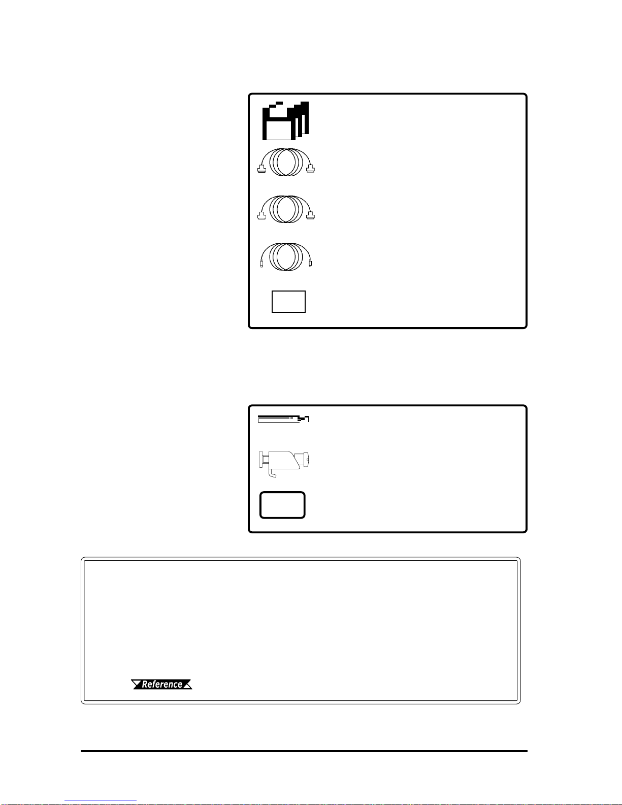
The FP's packing box contains the items listed below. Please check to be sure each is
included and is not damaged.
FP unit (FP790-T21)
CD-ROM *1 Installation brackets (12)
(contains the PDF manuals) <GP070-AT01>
Package Contents
FP-790T Installation Guide
FP-790T
Installation
Guide
These items have all been carefully packed with special attention to product quality.
However, should you find any item(s) damaged or missing, please contact your local
distributor immediately for prompt service.
Installation gasket
<FP790-WP00>
*1 For description and usage of the application programs stored in the floppy disk, see
that disk's English “READ_ME.DOC” file.

FP-790T User Manual10
Symbol Meaning
Used to indicateimportantinformationor procedures thatmustbe followedfor
correctandrisk-freesoftware/deviceoperation.
Used to refer to useful or importantsupplemental information.
Used to provide useful or importantsupplementalinformation.
*1 Used to provide useful or importantsupplementalinformation.
1) , 2) Indicates steps in a procedure. Be sure to perform these steps in the order
given.
Symbol Information
The list below describes the symbols used in this manual.

1-1FP-790T User Manual
The following diagram illustrates the connection options available between the FP
and a PC.
Chapter 1
Introduction
1. Connecting the FP to a PC
2. Optional Equipment
Microsoft Mouse
(Commercially available type)
Mouse/Keyboard cable
(Keyboard output)
FP-CK01
SIO cable (RS-232C)
FP61V-IS00-O
RGB cable
(Analog RGB input)
FP-CV00, FP-CV01
DOS compatible
personalcomputer
<OS>
Windows95
Windows98
Windows NT
Windows2000
d
e
f
g
h
i
FP Unit
(FP790-T21)
For a description of each reference no. used (h, etc.) refer to the next
page (page 1–2)
c
1-1 Connecting the FP to a PC
The interface connecting a touch panel to a host PC is only RS-232C. It
cannot be communicated with the PS/2 interface.
Introduction
1-2 FP-790T User Manual
FP-790 Mouse Emulator for Windows
FP-ME000*1
Optional Maintenance Parts
These parts are included in
either the FP or its package as
standard equipment, and are
also optionally available for FP
maintenance.
Optional Parts
(Sold separately)
Backlight (2 lights/set)
FP790T-BL00-MS
Installation Brackets (4 brackets/set)
GP070-AT01
Installtion Gasket
FP790-WP00
Page 1–1 Item Description
FP Interface
cMouse Connector
dSerial I/F Connector
eAnalog RGB I/F Connector
fHost Connector for Mouse
2-5 Names and Functions of FP Parts
Mouse/Keyboard Cable
FP-CK01
Serial I/F Cable
FP61V-IS00-0
Analog RGB Cable
FP-CV00/FP-CV01
Display Protection Sheets (5 sheets/set)
PL-CS500
*1 The FP-ME000 (Mouse Emulator) can only be used with a PC running
the Japanese version of Windows. When an English version of Win-
dows is used, the English version of the U-TP (Gunze Corporation)
software is required. For purchasing information, contact your local
Pro-face distributor.
Personal Align Computer Interface
gMouse interface
hSerial interface
iAnalog RGB interface

Introduction
1-3FP-790T User Manual
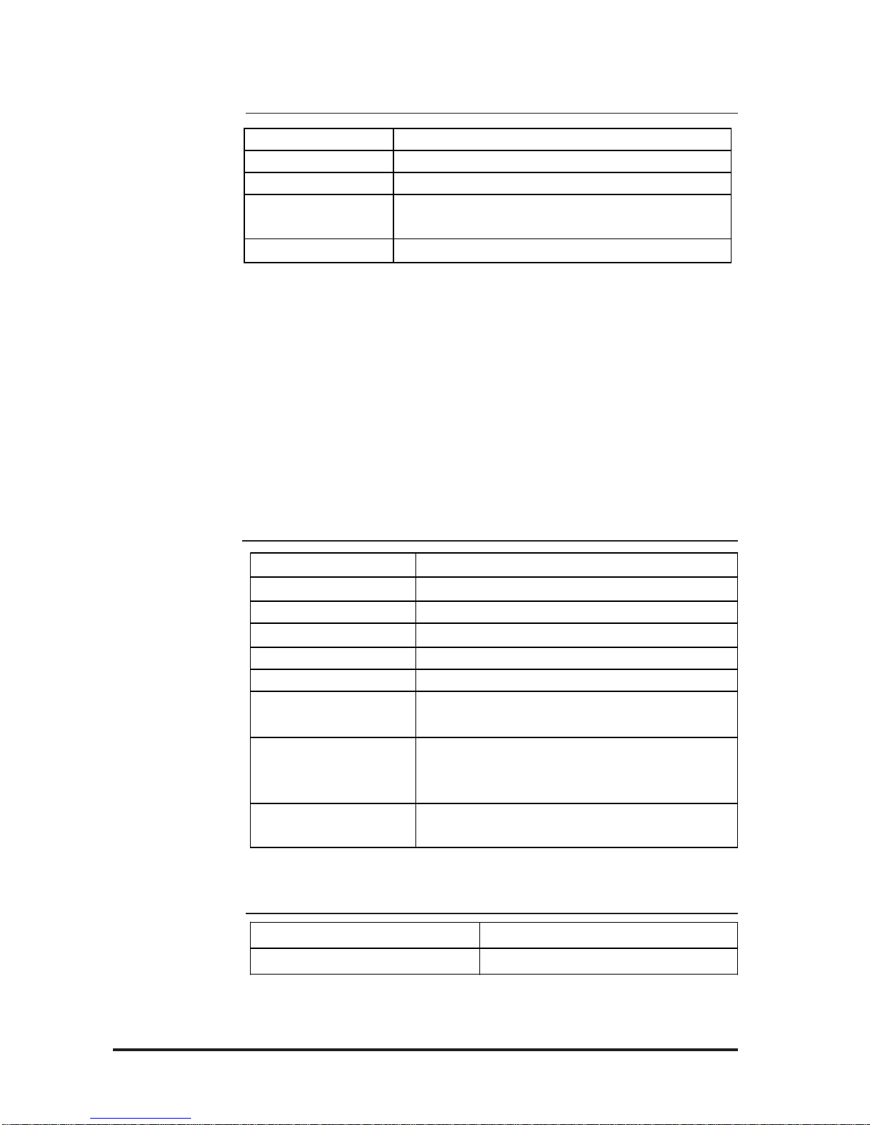
1-2 Optional Equipment
All optional equipment listed below are products of Digital Electronics Corp.
Model No. Description
SIO cable FP61V-IS00-O
Serialinterface cableusedfortransmissionof
touchpaneldata betweentheFPandvarious
hosts(PCs),andforthe transmissionof
commands to the FP. (5 m)
Compatible with PC/AT (D-sub 9-pin female
connector)computers
RGBcable
(2.5m) FP-CV00
AnalogRGBinterfacecableusedto output
image signalsfrom varioushost(PCs)to the
FP.(2.5 m)
CompatiblewithanalogRGBinterface(D-sub
15-pin maleconnector).
RGBcable
(5m) FP-CV01
AnalogRGBinterfacecableusedto output
image signalsfrom varioushost(PCs)to the
FP. (5 m)
CompatiblewithanalogRGBinterface(D-sub
15-pin maleconnector).
Mouse/
Keyboard
cable FP-CK01
Usedtoconnectamousebetweenthe hostand
the FP. (2.5 m)
CompatiblewithPS-2(miniDIN4-pinmale
connector)devices.
Akeyboardcannotbeconnected.
Optional
Software
FP-790
Mouse
Emulator FP-ME000*1Touch paneldriverforWindows95,98,NT,
2000
Backlight FP790T-BL00 ReplacementBacklights (2lights/set)
Installation
brackets GP070-AT01 UsedtosecuretheFPtoitsinstallationpanel.
(4 brackets/set)
Installation
gasket FP790-WP00 Used to preventmoisture from entering the FP’s
chassis.Samegasketasoriginallyincluded
with the FP.
Optional
Parts
Display
protection
sheets FP77-COVER-5P
Disposable sheetsthatprotectthedisplayfrom
dustand dirt.Thetouchpanelcan beused
whenoneofthesesheetsisattached.(5
sheets/set)
Maintenance
Parts
Interfaces
ItemName
*1 The FP-ME000 (Mouse Emulator) can only be used with a PC running the Japanese version of
Windows. When an English version of Windows is used, the English version of the U-TP (Gunze
Corporation) software is required. For purchasing information, contact your local Pro-face dis-
tributor.

1-4 FP-790T User Manual
MEMO

FP-790T User Manual 2-1
Chapter 2
Specifications
1. General Specifications 4. Option Cable Pin Diagrams
2. Functional Specifications 5. Names and Descriptions of FP Parts
3. Interface Specifications 6. Flat Panel (FP) Dimensions
2-1-1 Electrical Specifications
2-1 General Specifications
This chapter includes general specifications, functional specifications, interface
specifications, and part names and dimensions of the FP.
InputVoltage AC100VtoAC240V 50/60Hz
Rated Voltage AC85VtoAC265V 50/60Hz
Allowable Voltage Drop 1cycleorless
PowerConsumption 65VAor less
In-Rush Current 30A(atnormal temperature),45A(at400C)
VoltageEndurance AC1500V 20mA 1 minute
(betweenthelivewireand grounding terminals)
Isolation Resistance DC500V10MΩgreater
(betweenthelivewireandgroundingterminals)
FP-790T User Manual
Specifications
2-2
2-1-3 Environmental Specifications
2-1-4 Touch Panel Specifications
Resolution (dot) 1024X1024
Method Resistive Film (Analog)
Operating Temperature 00Cto400C
Storage Temperature -100C to600C
Ambient Humidity 30%RH to 85%RH(non-condensing)
Dust 0.1mg/m3orless(non-conductive levels)
Atmosphere Freeofcorrosivegases
AtmosphericEndurance 800hPato1114hPa(2000metersorlower)
Vibration Resistance 10Hzto25Hz
(X,Y,Z directions: 30 minuteseach,19.6m/s2)
Noise Immunity
(vianoisesimulator)
NoiseVoltage: 1500Vp-p
PulseDuration: 50ns,500ns,1µs
Rise Time : 1 ns
Electrostatic Discharge
Immunity 4kV IEC 61000-4-2
2-1-2 Structual Specifications
*1 The front face of the FP unit, installed in a solid panel, has been tested using conditions
equivalent to the standard shown in the specification. Even though the FP unit’s level of
resistance is equivalent to the standard, oils that should have no effect on the FP can
possibly harm the unit. This can occur in areas where either vaporized oils are present, or
where low viscosity cutting oils are allowed to adhere to the unit for long periods of time. If
the FP’s front face protection sheet becomes peeled off, these conditions can lead to the
ingress of oil into the FP and separate protection measures are suggested. Also, if non-
approved oils are present, it may cause deformation or corrosion of the front panel’s plastic
cover. Therefore, prior to installing the FP be sure to confirm the type of conditions that
will be present in the FP’s operating environment.
If the installation gasket is used for a long period of time, or if the unit and its gasket are
removed from the panel, the original level of the protection cannot be guaranteed. To main-
tain the original protection level, you need to replace the installation gasket regularly.
Grounding 100Ωorless,oryourcountry'sapplicablestandard
Cooling Method Natural aircirculation
Weight 6.5kg[14.3lbs.]orless(Unitonly)
External Dimensions W405mm [15.94in.]x H350mm [13.78in.]x D75mm [2.95in.]
(notincludingrearprojections)
Ratings*1 Equivalent to IP65f (JEM 1030)

FP-790T User Manual
Specifications
2-3
2-2 Functional Specifications
2-2-1 Display Specifications
2-1-5 Display Specifications
Display Media TFT colorLCD
Display Colors 260,000
ContrastAdjustment Possibleviaadjustmentmenu
Dot Pitch W0.273mm xH0.273mm
TouchPanel Resolution 1024x1024
Display Area 285.7mm [11.25in.]x214.3mm [8.44in.]
DisplayMode
(selected via switch)
640x480(VGA)
720x400(USText)
800x600(SVGA)
1024x768(XGA)
Backlight CFL
(undercontinuous24houroperation,
lifespan=30,000hours)
InputSignal AnalogRGB
ImageSignal AnalogRGB
SynchronousSignal TTL Level,negativeTrueorpositivetrue
ScanningType Non-interlaced
Clockadjustment:-128to128
Phaseadjustment:64levels
ContrastControl viatouch panel
BrightnessControl viatouch panel
ColorControl viared,green,bluesettings
Horizontal Display
VerticalDisplay
Serial I/F
(RS-232C)
(MOUSEIN) PS/2Interface mini DIN6-pinfemale
(MOUSEOUT) PS/2Interface mini DIN4-pinfemale
MouseI/F
Analog RGB I/F
(RGB IN)
Positioningcontrol
DisplayAdjustment
AsynchronousTransmission,RS232C,DataLength:8bits,StopBit:
1,Parity:None,OddorEven,TransferSpeed:9600bps
FP-790T User Manual
Specifications
2-4
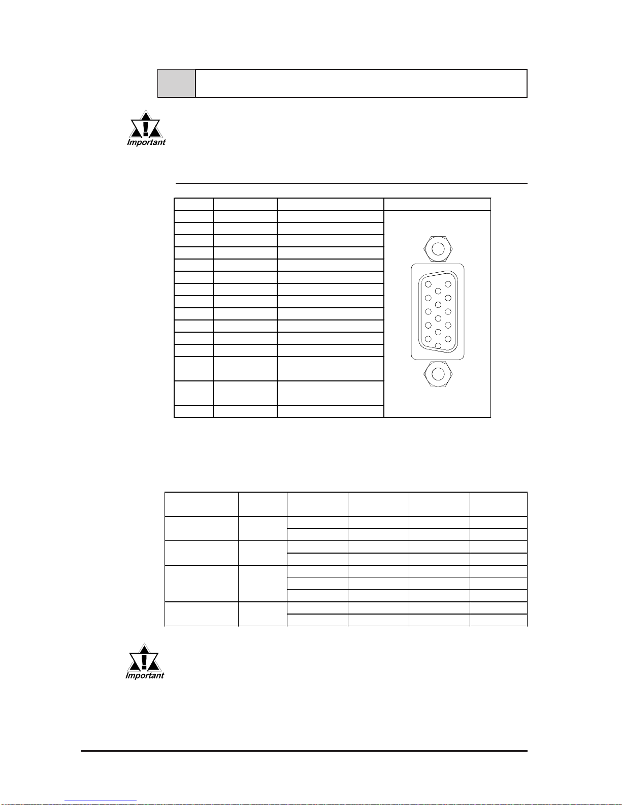
2-3-1 Analog RGB Interface (RGB IN)
2-3 Interface Specifications
Be sure to use Proface's optional cable. If any other cable is used, due to
possible noise interference, Proface cannot guarantee the FP will perform
as specified.
VESAStandard Horizontal Vertical DotClock SyncLogic
DisplayMode Frequency Frequency Frequency V.H
31.469kHz 59.992Hz 25.175MHz -,-
37.500kHz 75.000Hz 31.500MHz -,-
37.879kHz 60.317Hz 40.000MHz +,+
46.875kHz 75.000Hz 49.500MHz +,+
48.363kHz 60.004Hz 65.000MHz -,-
56.476kHz 70.069Hz 75.000MHz +,+
60.023kHz 75.029Hz 78.750MHz +,+
31.469kHz 70.087Hz 28.322MHz +,-
37.927kHz 85.039Hz 35.500MHz +,-
720×400
VGA
SVGA
XGA
USText
Size
640×480
800×600
1024×768
Pin No. Signal Name Condition Pin Location
1ANALOG R R SignalInput
2ANALOG G G Signal Input
3ANALOG B BSignalInput
4NC NoConnection
5GND GND
6RETURN R R Signal GND
7RETURN G G Signal GND
8RETURN B BSignal GND
9NC NoConnection
10 GND GND
11 NC NoConnection
12 NC NoConnection
Horizontal Synchronous
Signal Input
VerticalSynchronous
Signal Input
15 NC NoConnection
H.SYNC13
V. SYNC14
The allowable frequency fluctuation range in both the horizontal and
vertical frequencies is +/- 1%. If fluctuations exceed these ranges,
the FP will enter power save mode and the display will go blank.
Recommended Connector: Mini Dsub 15 pin (JST Co.) KEY-15S-2A3F eqivalent
Connector set screw: Inch type (4-40UNC)
Cable: Digital Electronics Corporation RGB cable (FP-CV00,
FP-CV01)

FP-790T User Manual
Specifications
2-5
2-3-2 RS232C Interface (COM1/COM2/COM3)
Pin Assignments and Signal Names for Serial Interface Connector
1
5
6
9
Signal Names
Signal names used for the FP's serial interface are designed to match the
pin order used on most PC serial interfaces, so that a straight cable can be
used to connect the two. Therefore, connect each pin's signal to the same
signal name on the PC connector.
For example, pin #2 'RD' should be connected to the 'RD' input terminal
on the FP's connector.
Refer to section "2-4 Option Cable Pin Diagrams" for information about
each signal's direction.
Pin No. Signal
Name Condition Pin Location
1CD CarrierDetect(FP–>Host)
2RD Receive Data(FP–>Host)
3TD SendData(FP<–Host)
4DTR DataTerminalReady(FP<–Host)
5GND Ground
6DSR DataSetReady(FP–>Host)
7RTS RequesttoSend(FP<– Host)
8CTS CleartoSend(FP–>Host)
9RI NotUsed
• Since all serial interface signals are the same on the PC side, use a
straight cable to connect the FP to the PC.
• The GND terminal is the signal ground. Be sure to connect the GND
terminal to other unit’s SG (signal ground).
Recommended Connector: Mini Dsub 9-pin (JST Co.) JEY-9P-1A3F eqivalent
Connector set screw: Inch type (4-40UNC)
Cable: Digital Electronics Corporation SIO cable
(FP-61V-IS00-0)
Table of contents
Other Pro-face Monitor manuals

Pro-face
Pro-face GP-3600T Series User manual

Pro-face
Pro-face PS-3000B Series User manual

Pro-face
Pro-face GP77R Series Instruction manual

Pro-face
Pro-face FP2650-T41 User manual

Pro-face
Pro-face FP3900-T41 User manual

Pro-face
Pro-face GC4000 Series User manual

Pro-face
Pro-face FP3650-T41 User manual

Pro-face
Pro-face Xycom SXT1811 Installation instructions

Pro-face
Pro-face SP-5600TP User manual

Pro-face
Pro-face SP5000 Series User manual


