Pro-face GP-4000M User manual

1/46
Easy! Smooth!
GP-37W2 GP4000M Series
Replacement Guidebook
3rd Edition 2014.11
Copyright © 2014.11 Digital Electronics Corporation. All Rights Reserved.

2/46
Preface
This manual introduces the procedures to replace a GP-37W2 unit with a GP4X01TM
unit.
Model in use
Recommended Substitution
GP-37W2
GP-4301TM
Safety Information
HAZARD OF OPERATOR INJURY, OR UNINTENDED EQUIPMENT DAMAGE
Before operating any of these products, be sure to read all related manuals thoroughly.
Failure to follow these instructions can result in death, serious injury or unintended equipment
damage.

3/46
Contents
PREFACE 2
CONTENTS 3
CHAPTER 1 SPECIFICATION COMPARISON 5
1.1 SPECIFICATIONS OF GP-37W2 AND GP-4301TM 5
CHAPTER 2 COMPATIBILITY OF HARDWARE 6
2.1 LOCATIONS OF CONNECTORS 6
2.2 TOUCH PANEL SPECIFICATIONS 7
2.3 DISPLAY COLORS 7
2.4 PANEL CUTOUT DIMENSIONS 7
2.5 EXTERNAL DIMENSIONS 8
2.6 TRANSFER CABLE 8
2.7 SERIAL INTERFACE 8
2.8 MEMORY 9
2.9 PERIPHERAL UNITS AND OPTION UNITS 9
2.9.1 BARCODE READER CONNECTION 9
2.9.2 ISOLATION UNIT 9
2.10 POWER CONNECTOR 9
2.11 POWER CONSUMPTION 10
2.12 OTHER NOTES 10
CHAPTER 3 REPLACEMENT PROCEDURE 11
3.1 WORK FLOW 11
3.2 PREPARATION 12
3.3 RECEIVE SCREEN DATA FROM GP-37W2 13
3.4 CONVERT SCREEN DATA WITH THE PROJECT CONVERTER 17
3.5 TRANSFER SCREEN DATA TO GP-4301TM 25

4/46
3.6 DIFFERENCES OF SOFTWARE 29
3.6.1 DIFFERENCES AFTER CONVERSION 29
3.6.2 DIFFERENCES MADE AT THE TIME OF CHANGE TO GP-4301TM 31
CHAPTER 4 COMMUNICATION WITH DEVICE/PLC 32
4.1 DRIVER LIST 32
4.2 SHAPES OF COM PORTS 33
4.3 SIGNALS OF COM PORTS 34
4.4 MULTILINK CONNECTION 36
4.5 INTERNAL 2-PORT FEATURE FOR MITSUBISHI PLC 36
4.6 CABLE DIAGRAM AT THE TIME OF REPLACEMENT 37
4.6.1 WHEN USING A RS-232C CONNECTION CABLE 38
4.6.2 WHEN USING A RS-422 CONNECTION CABLE 39
CHAPTER 5 APPENDIX 43
5.1 WHEN THE DISPLAY UNIT TYPE CANNOT BE CHANGED 43

5/46
Chapter 1 Specification Comparison
1.1 Specifications of GP-37W2 and GP-4301TM
GP-37W2
GP-4301TM
Display Type
Monochrome blue mode LCD
NEW! TFT Color LCD
Display Colors,
Levels
Blue mode, no levels
UP! 65,536 colors
Display Resolution
QVGA (320x240 pixels)
Panle Cutout
Dimensions (mm)
191.5(W)x141.5(W)
NEW! φ22mm ->See 2.4
External Dimensions
(mm)
207(W)x157(H)x58(D)
NEW!
163(W)x129.4(H)x56.5(D)
*The main module is
included.
->See 2.5
Touch Panel Type
Matrix
NEW! Analog ->See 2.2
Memory
Application
1MB
UP! 8MB
Backup
96KB
UP! 128KB ->See 2.8
Rated Input Voltage
DC 24V
Serial
I/F
COM1
D-Sub 25 pin (socket)
RS-232C/422
NEW!
D-Sub 9 pin (plug)
RS-232C/422/485
->See 2.7
Ethernet I/F
-
UP! 10BASE-T/100BASE-TX
USB Host I/F
-
NEW! ✔->See 2.6
6/46
Chapter 2 Compatibility of Hardware
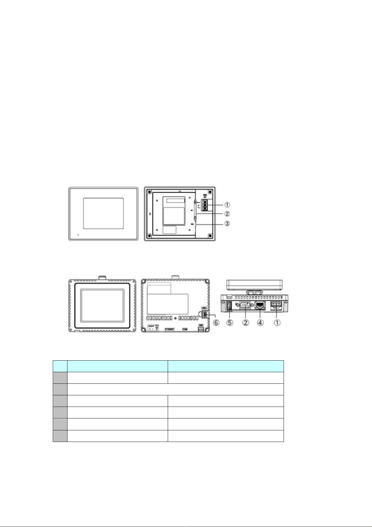
2.1 Locations of connectors
Connector locations on GP-37W2 and GP-4301TM are as follows:
GP-37W2
GP-4301TM
Interface names
GP-37W2
GP-4301TM
1
Power Input Terminal Block
Power Connector
2
Serial I/F (COM1)
3
Tool Connector
-
4
-
Ethernet I/F
5
-
USB I/F (Type A)
6
-
USB I/F (miniB)

7/46
2.2 Touch Panel specifications
GP-4301TM adopts the Analog type.
For the Analog type, even if you touch two points at the same time, it’s recognized that
the coordinates located between these two points are touched.
If you have applied the two-point touch input on GP-37W2, we recommend you to
change to the one-point touch input using the switch delay function of GP-Pro EX.
2.3 Display Colors
GP-37W2 has monochrome LCD, but GP-4301TM has TFT Color LCD. After
replacement, the black and white display changes to the color display.
When data of a monochrome model are converted to a color model with GP-Pro EX,
the data may be displayed in colors except black and white depending on a setting of
GP-PRO/PBIII. After conversion, please confirm the display colors of the drawing or
the parts on the screens just in case.
2.4 Panel cutout dimensions
The panel cutout of GP-4301TM is a φ22-mm circular hole. The panel cutout shape
and dimensions of GP-4301TM are different from those of GP-37W2.
8/46
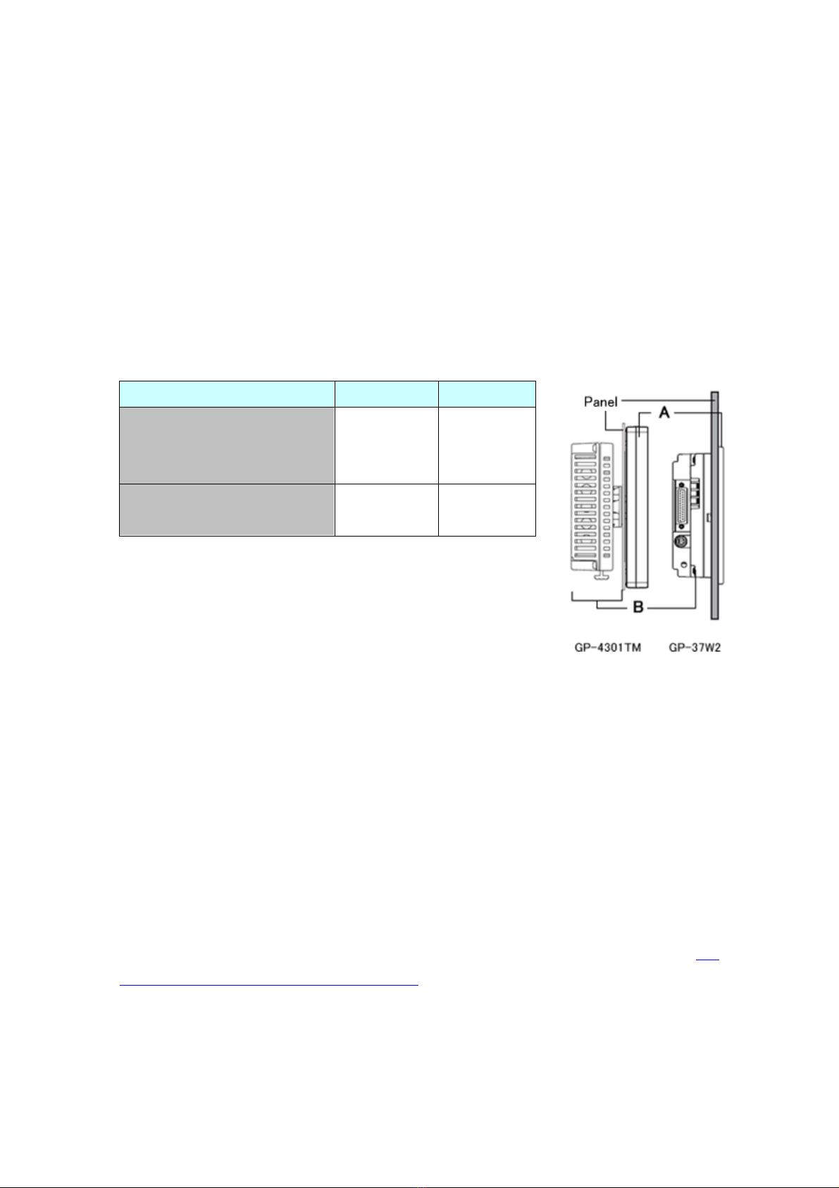
2.5 External Dimensions
For GP-4301TM, the front face display module (display part) and the back face main
module are separated. Compared with GP-37W2, the tickness of the part appearing
on the installation panel differs.
2.6 Transfer cable
To transfer screen data to GP-4301TM, use a USB transfer cable or Ethernet. Use a
USB data-transfer cable (model: ZC9USCBMB1) or a commercial USB cable (USB
A/mini-B). Please note that the cables (GPW-CB02, GPW-CB03, GP430-CU02-M) for
GP-37W2 cannot be used for GP-4301TM.
2.7 Serial interface
The COM1 port on GP-4301TM is D-sub 9 pin plug. The COM1 port of GP-37W2 is
D-sub 25 pin socket, and the pin assignment and the shape of plug/socket connector
are different from those of GP-4301TM. Because of it, the existing PLC connection
cables cannot be used as they are. If you use the existing connection cables, see [4.5
Cable Diagram at the time of replacement].
GP-37W2
GP-4301TM
A
(the thickness of the front
bezel)
6mm
17.5mm
B
(the depth of the back face)
52mm
39mm

9/46
2.8 Memory
GP-4301TM does not have SRAM, but uses a part of application memory as a backup
area. Data in the backup area is retained even after power off or reset of GP-4301TM
in the same way as SRAM. The functions possible for backup on GP-4301TM are as
follows:
- Alarm History (Up to 768)
- Recipe (Filing data)
- Brightness/Contrast values
* For the functions above, data is saved in the backup area at the time of ‘Save’.
* Sampling and clock data is not backed up.
2.9 Peripheral units and option units
2.9.1 Barcode reader connection
GP-4301TM is not equipped with a tool port. A barcode reader connected from the
tool port on GP-37W2 cannot be used. However, GP-4301TM allows you to connect
a barcode reader on its USB interface (Type A) or its serial interface.
For the models GP-4301TM supports, see [OtasukePro!]
(http://www.pro-face.com/otasuke/qa/3000/0056_connect_e.html).H
And if you connect a barcode reader to GP-4301TM, be sure to supply power to the
barcode reader from an external power source (such as a USB hub supporting
self-power supply). When no power is supplied from an external power source, if
the barcode reader consumes more electricity than expected, operation of
GP-4301TM will become unstable and reset may be activated.
2.9.2 Isolation Unit
The isolation unit for GP-37W2 (CA2-ISOALL232-01, CA2-ISOALL422-01) cannot
be used for GP-4301TM.
2.10 Power Connector
The power connector on GP-4301TM is a screw lock terminal block. If you replace
GP-37W2, change the power cable.

10/46
2.11 Power Consumption
The power consumption of GP-37W2 is different form that of GP-4301TM.
For the detailed electric specifications, see the hardware manual.
2.12 Other Notes
Do not expose GP4000 series to direct sunlight.
Do not use GP4000 series outdoors.
Do not turn on GP4000 series if condensation has occurred inside the device.
When you are continuously using GP4000 series without oxygen, the brightness might
decrease. Please ventilate the control panel periodically.
GP-37W2
GP-4301TM
20W or less
6.8W or less

11/46
Chapter 3 Replacement Procedure
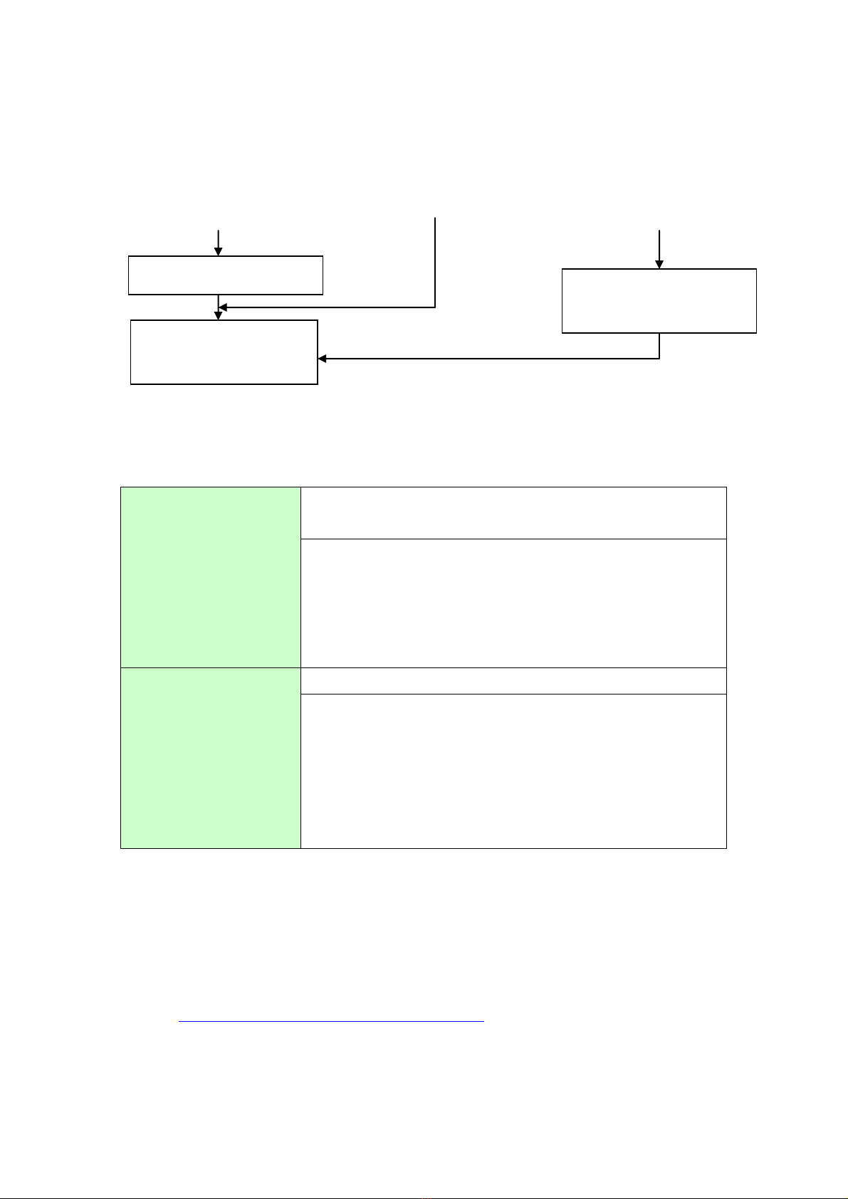
3.1 Work Flow
Receive the screen data
from GP-37W2. *1
Convert the data with
GP-Pro EX’s Project
Converter
Check and modify the data
in GP-Pro EX.
Connect GP-4301TM and
PLC with a cable.
Remove GP-37W2.
Installation
Screen
Communication
Process the panel and
install GP-4301TM.
Check the compatibility of
hardware in Chapter 2.
Check the connection
between GP-4301TM and
PLC in the GP-Pro EX
Device/PLC Connection
Manual.
Check the differences of
specifications in the booklet
[Compatibility of Software]
on OtasukePro!
(http://www.pro-face.com/
otasuke/qa/gp3000/replace
/soft/conv/care/3/)
Transfer the screen data to
GP-4301TM.
12/46
3.2 Preparation
Requirements for
receiving screen data
from GP-37W2 *1
PC in which GP-PRO/PB3 for Windows Ver. 4.0 or later is
installed (*2)
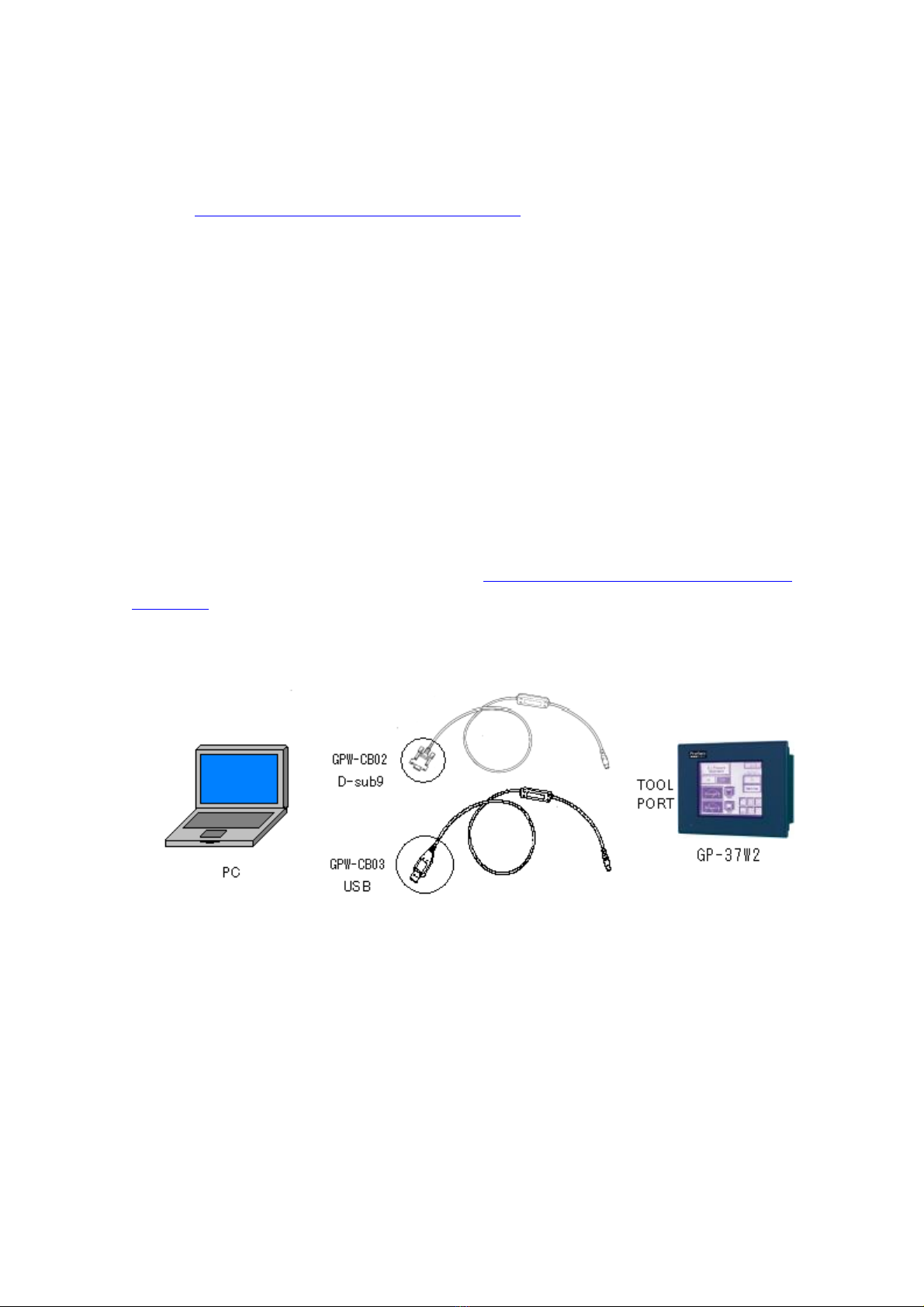
Transfer cable
(The following three types of cables are available.)
・GPW-CB02 (D-sub 9-pin to the PC)
・GPW-CB03 (USB to the PC *3)
・GP430-CU02-M or GPW-SET (D-sub 25-pin to PC)
Requirements for
converting screen data
of GP-37W2 and
transferring to
GP-4301TM
PC in which GP-Pro EX Ver.2.71 or later is installed.
A USB data-transfer cable
(The following three types of cables are available.)
・A USB data-transfer cable (model: ZC9USCBMB1)
・A commercial USB cable (USB Type A/mini B)
* Possible to send/receive a screen with a USB flash drive
or via Ethernet.
*1: This step is required if screen data is saved only in the GP unit, not in any other device.
*2: The software version must be the same or higher than the version that you used when creating
screen data for the GP-37W2 unit.
We recommend you upgrade to the latest version, which is GP-PRO/PBIII for Windows
C-Package03 (SP2) Ver. 7.29. If the version of GP-PRO/PBIII for Windows C-Package03 that you
currently use is version 7.0, upgrade it on our website [Otasuke Pro!]
(http://www.pro-face.com/otasuke/download/update/)
*3: GPW-CB03 is compliant with GP-PRO/PBIII for Windows C-Package02 (SP2) Ver. 6.23 or later.
Also, to use it, you may need to Install the driver on our website [OtasukePro!]
Start connection and check
the communication.
Connect the power cord.
Check the performance
and start operation.
*1: This step is required if screen data is saved only in the GP unit, not in any other device.
13/46
(http://www.pro-face.com/otasuke/download/driver/).
3.3 Receive screen data from GP-37W2
This section explains, as an example, how to receive screen data from GP-37W2 using
a transfer cable, GPW-CB02 or GPW-CB03. If you have backed up screen data, this
step is unnecessary; skip to the next section [3.4 Convert screen data with the Project
Converter].
(1) Connect a transfer cable to the GP-37W2 unit.
(2) Start up GP-PRO/PBIII for Windows and click the [Transfer] icon on the Project
Manager (Specify a desired project file.)

14/46
(3) On the [Transfer] window, select the [Setup] menu and click [Transfer Settings…].
(4) In the Communication Port field, select [COM], specify the COM port to which the
cable is connected, and click [OK].
15/46
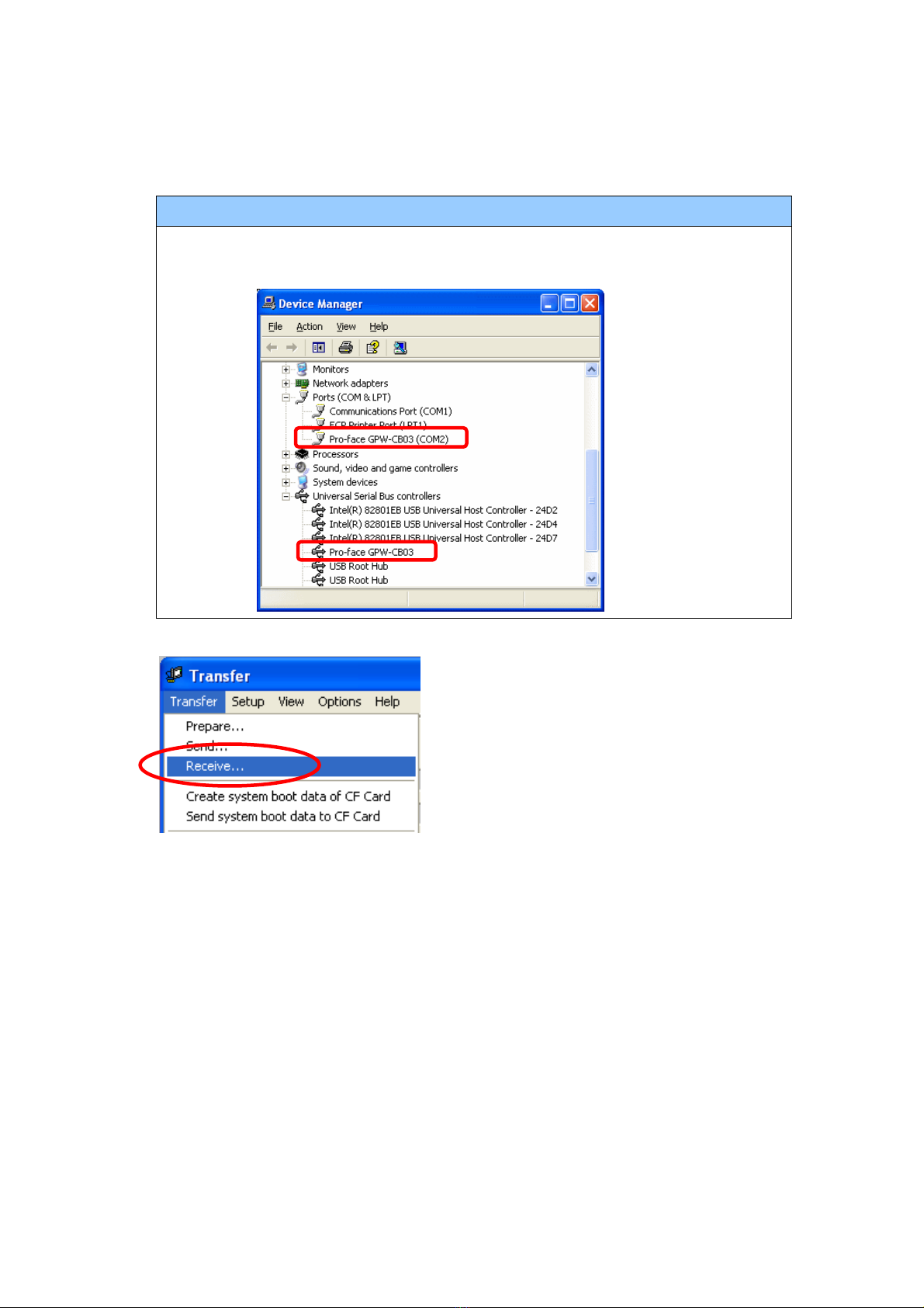
If you use a USB transfer cable (GPW-CB03)
You can check the COM port for the USB transfer cable (GPW-CB03), which is
assigned to the PC, with the Device Manager of Windows.
(5) Select the [Transfer] menu and click [Receive…].
(6) Specify the location to save the received screen data in and the project file name
and save.

16/46
In case there is no Upload Information
“Upload Information” is necessary to receive screen data from GP-37W2. It needs
to be included in screen data when transferring screen data to the display unit
beforehand. The Upload Information is sent to the display unit by default,
however, you may check off the box of Upload Information to prevent screen
reception by a third party.
You can check if the Upload Information has been sent or not in the following way.
1. Enter into the GP’s Offline mode
2. If there are 2 asterisk (*) marks in the Main menu as shown below, the
Upload Information has been sent.

17/46
If not, there is no “Upload Information” sent. In this case, a message, which
indicates there is no “Upload Information”, appears and you cannot receive the
data.
3.4 Convert screen data with the Project Converter
Convert a project file (*.prw) for GP-37W2 with the GP-Pro EX’s Project Converter and
change the model setting to GP-4301TM.
(1) Click the [Start] button, select [All Programs] (or [Programs])-> [Pro-face]->
[GP-Pro EX *.**]->[Project Converter].
(For this part, [*.**], the version of the software you use is displayed.)

18/46
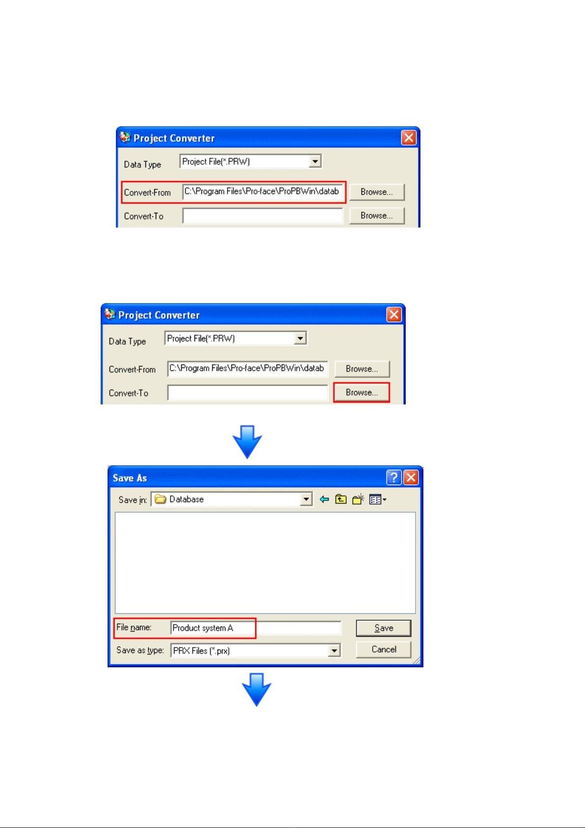
(2) The Project Converter starts up and the [Project Converter] dialog box opens.
Select [Project File (*.PRW)] in the [Data Type].
(3) Click the [Browse…] button and select a project file (e.g.: “Project system A.prw”).
Click [Open], and the file will be set in [Convert-From].
19/46
(4) In [Convert-To], designate a GP-Pro EX’s project file (*.prx). Click the [Browse…]
button and enter a new [File Name] (e.g.: “Product system A.prx”). Click [Save],
and a new project file will be set to [Convert-To].

20/46
NOTE
When a convert-to file exists, the window that confirms whether or not to overwrite
the file is displayed.
(5) Click [Convert] and start the conversion.
This manual suits for next models
2
Table of contents
Other Pro-face Monitor manuals

Pro-face
Pro-face FP-790T User manual

Pro-face
Pro-face GP-3300T Manual

Pro-face
Pro-face GP577R-TC11 User manual

Pro-face
Pro-face GP-3750T User manual

Pro-face
Pro-face FP2650-T41 User manual

Pro-face
Pro-face SP5000 Series User manual

Pro-face
Pro-face GP-3600T Series User manual

Pro-face
Pro-face SP-5600TP User manual

Pro-face
Pro-face FP3900-T41 User manual

Pro-face
Pro-face PL-X900 Series User manual


