Pro-face PS-3000B Series User manual

Hardware Manual
PS-3000B Series
Industrial automation
Elincom Group
EuropeanUnion:www.elinco.eu
Russia:www.elinc.ru

1
Preface
Thank you for purchasing Pro-face’s PS-3000B Series (Hereafter referred to as the “PS-B unit”).
Before operating your PS-B unit, be sure to read this manual to familiarize yourself with the PS-B unit’s operation
procedures and features.
©2008 Copyright Digital Electronics Corporation. All rights reserved.
Product names used in this manual are the trademarks / registered trademarks of their respective owners.
NOTICE
1. Copying this manual’s contents, either in whole or in part, is prohibited without the express permission of Digital
Electronics Corporation, Japan.
2. The information contained in this manual is subject to change without notice.
3. If you should you find any errors or omissions in this document, please contact Digital Electronics Corporation to
report your findings.
4. Regardless of Clause 3 above, Digital Electronics Corporation shall not be held responsible for any damages,
losses or third-party damages resulting from the use of this product.
2
Essential Safety Precautions
All safety-related procedures stated in this document must be followed to operate the PS-B correctly and safely. Be sure to
read this and any related documents thoroughly to understand the correct operation and functions of the PS-B unit.
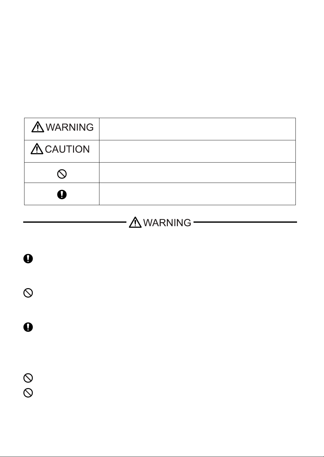
Safety Icons
Throughout this manual, these icons provide essential safety information for PS-B operation procedures requiring special
attention. These icons indicate the following levels of danger:
System Design
Handling
Indicates situations where severe bodily injury, death or major equipment damage
can occur.
Indicates situations where slight bodily injury or minor equipment damage can
occur.
Indicates actions or procedures that should NOT be performed.
Indicates actions or procedures that MUST be performed to ensure correct unit
operation.
Be sure to design your system so that a communication fault between the PS-B and its host controller will
not cause equipment to malfunction. This is to prevent any possibility of bodily injury or equipment
damage.
Do not use the PS-B with aircraft control devices, aerospace equipment, central trunk data transmission
(communication) devices, nuclear power control devices, or medical life support equipment, due to these
devices’ inherent requirements of extremely high levels of safety and reliability.
When using the PS-B with transportation vehicles (trains, cars, and ships), disaster and crime prevention
devices, various types of safety equipment, and medical devices that are not life-support related, use
redundant and/or failsafe system designs to ensure proper reliability and safety.
Do not disassemble or modify the PS-B unit. Doing so may cause a fire or an electric shock.
Do not operate the PS-B in an environment where flammable gases are present, since it may cause an
explosion.

3
Wiring
Maintenance
To prevent electrical shock or equipment damage, unplug the PS-B unit’s power cord from the power
supply prior to installing or wiring the PS-B.
Do not use the voltage not specified in the manual. Doing so may cause a fire or an electric shock.
Do not connect or disconnect Host and PS-B unit communication cables while the PS-B is turned ON.
The PS-B uses a lithium battery for backing up its internal clock data and the battery may explode if it is
replaced incorrectly. When replacement is required, use a Pro-face-designated replacement product.
SEE “4.3 Replacing the Internal Battery” (page 4-4)

4
Installation
Wiring
Maintenance
Unit Disposal
General Safety Precautions
Be sure all cable connectors are securely attached to the PS-B unit. A loose connection may cause
incorrect input or output signals.
Be sure to ground the PS-B unit’s FG wire separately from other equipment FG lines. Also, be sure to use
a grounding resistance of 100Ωor less and a 2mm2or thicker wire, or your country’s applicable standard.
Otherwise, electric shock or malfunctions may result.
Be sure to use only the designated torque to tighten the PS-B unit’s terminal block screws. If these screws
are not tightened firmly, it may cause a short-circuit, fire or incorrect unit operation.
Be sure that metal particles and wiring debris do not fall inside the PS-B unit. They can cause a fire,
malfunction or incorrect unit operation.
Do not reset or turn the PS-B OFF, or insert or remove the CF Card while the PS-B unit’s CF Card or hard
disk is being accessed. Otherwise, CF Card and the hard disk internal data may be damaged or lost.
When the product is disposed of, it should be done so according to your country’s regulations for similar
types of industrial waste.
Do not install the PS-B where the ambient temperature exceeds the specified range. Doing so may cause
a unit malfunction.
To prevent abnormally high temperatures from occurring inside the PS-B, do not restrict or block the PS-B
unit’s rear-face ventilation slots.
Do not operate the PS-B in areas where large, sudden temperature changes can occur. These changes
can cause condensation to form inside the PS-B, possibly causing it to malfunction.
Do not allow water, liquids or metal fragments to enter inside the PS-B unit’s case, since they can cause
either a malfunction or an electric shock. The allowable pollution degree is 2.
Do not operate or store the PS-B in locations where it can be exposed to direct sunlight, high
temperatures, excessive dust, moisture or vibration.

5
Do not operate or store the PS-B where chemicals evaporate, or where chemicals are present in the air.
Corrosive chemicals: Acids, alkalines, liquids containing salt
Flammable chemicals: Organic Solvents
Do not use paint thinner or organic solvents to remove dirt or oil from the PS-B unit’s surface. Instead, use
a soft cloth moistened with a diluted neutral detergent.
After turning OFF the PS-B, be sure to wait a few seconds before turning it ON again. The PS-B may not
operate correctly if it is restarted too quickly.
Due to the possibility of unexpected accidents, be sure to back up the PS-B unit’s data regularly.

6
Information Symbols
This manual uses the following icons:
Indicates a warning or a product limitation. Be sure to follow the instructions given with
this icon to ensure the safe operation of the PS-B.
* Indicates useful or important supplemental information.
Contains additional or useful information.
Indicates pages containing related information.
SEE

7
Package Contents
The following items are included in the PS-B unit’s package. Before using the PS-B, please check that all items listed here
are present.
This unit has been carefully packed, with special attention to quality. However, should you find anything damaged or
missing, please contact your local PS-B distributor immediately.
PS-B Unit: 1 • Installation Guides
(Set of Japanese/
Set of English)
• Warning/Caution
Information (1)
Installation Fasteners Set: 1
(Fasteners: 2, Screws:4)
PS3000-BA PS3001-BD
USB Cable Clamp: (2 ports) 2 USB Holder: 1 Screw: 1
Power Connector: 1 (AC type: Included, DC type: Attached to the PS-B unit)
• Be careful when installing the PS-B not to damage the built-in HDD.
(for AC type)
(5.08mm [0.2in.] pitch) (for DC type)
(7.62mm [0.3in.] pitch)

8
UL/c-UL/CSA Approval
• UL listed products
• c-UL listed products
• CSA listed products
• Product List
UL/c-UL File No.: E220851
CSA File No.219866
<Cautions>
Be aware of the following items when building the PS-B into an end-use product:
• The PS-B unit is approved as an open-type unit.
• Install the PS-B unit on a flat surface. The PS-B unit must be mounted according to the installation requirements with
the specified distance from adjacent structures and equipment. The temperature must be checked on the final product
in which the PS-B is installed.
CE Marking
PS3000-BA units are CE marked products that conform to EMC directives and Low Voltage Directives EN55011 Class
A, EN61000-6-2 and EN60950-1.
PS3001-BD units are CE marked products that conform to EMC directives EN55011 Class A and EN61000-6-2.
Industrial Control Equipment refer to UL508 see [a] in the
“Product List“
Process Control Equipment refer to CSA-C22.2
No.142 see [b] in the
“Product List“
Process Control Equipment refer to CSA-C22.2
No.142 see [c] in the
“Product List“
Product Model No. Registration Model No. UL c-UL CSA
[a] [b] [c]
PS3000-BA 3681601-01 999
PS3001-BD 3681601-12 999

9
FCC Statement
United States FCC Part 15, Subpart B, Class A EMI Compliance Statement:
NOTE: This equipment has been tested and found to comply with the limits for a Class A digital device, pursuant to part
15 of the FCC Rules. These limits are designed to provide reasonable protection against harmful interference when the
equipment is operated in a commercial environment. This equipment generates, uses, and can radiate radio frequency
energy and, if not installed and used in accordance with the instruction manual, may cause harmful interference to radio
communications. Operation of this equipment in a residential area is likely to cause harmful interference in which case the
user will be required to correct the interference at his or her own expense.

10

11
Contents
Preface...................................................................................................................... 1
Essential Safety Precautions..................................................................................... 2
Information Symbols.................................................................................................. 6
Package Contents..................................................................................................... 7
UL/c-UL/CSA Approval.............................................................................................. 8
CE Marking................................................................................................................ 8
FCC Statement.......................................................................................................... 9
Chapter 1 Overview
1.1 System Design................................................................................................1-2
1.1.1 PS3000-BA...........................................................................................................1-2
1.1.2 PS3001-BD...........................................................................................................1-3
1.2 Accessories ....................................................................................................1-4
1.2.1 Option Items .........................................................................................................1-4
1.2.2 Maintenance Items ...............................................................................................1-4
1.3 Part Names and Functions.............................................................................1-5
1.3.1 PS3000-BA...........................................................................................................1-5
1.3.2 PS3001-BD...........................................................................................................1-7
1.4 Prior to Operating the PS-B Unit.....................................................................1-9
1.4.1 Power Supply........................................................................................................1-9
Chapter 2 Specifications
2.1 PS3000-BA.....................................................................................................2-2
2.1.1 General Specifications..........................................................................................2-2
2.1.2 Performance Specifications ..................................................................................2-5
2.1.3 Interface Specifications.........................................................................................2-7
2.1.4 Dimensions.........................................................................................................2-16
2.2 PS3001-BD...................................................................................................2-19
2.2.1 General Specifications........................................................................................2-19
2.2.2 Performance Specifications ................................................................................2-21
2.2.3 Interface Specifications.......................................................................................2-22
2.2.4 Dimensions.........................................................................................................2-30
Chapter 3 Installation and Wiring
3.1 Installation • Uninstallation..............................................................................3-2
3.1.1 Installation.............................................................................................................3-2
3.2 Peripheral Devices Installation........................................................................3-6

12
3.2.1 Main Memory Installation......................................................................................3-6
3.2.2 Expansion Board (PCI) Installation.......................................................................3-7
3.2.3 HDD Unit Installation...........................................................................................3-10
3.2.4 CF Card Insertion/Removal ................................................................................3-12
3.2.5 USB Cable Clamp Attachment/Removal ............................................................3-14
3.3 Wiring Precautions........................................................................................ 3-16
3.3.1 Connecting the Power Cord................................................................................3-16
3.3.2 Connecting the Power Supply.............................................................................3-20
3.3.3 Grounding...........................................................................................................3-21
3.3.4 I/O Signal Line Placement ..................................................................................3-22
Chapter 4 Maintenance
4.1 Cleaning the Fan Filter ...................................................................................4-2
4.2 Periodic Check Points.....................................................................................4-3
4.3 Replacing the Internal Battery ........................................................................ 4-4


PS-3000B Series Hardware Manual
1-2
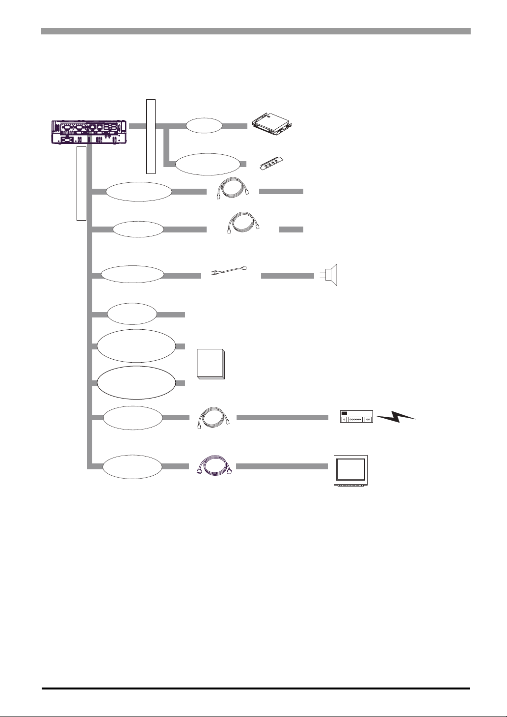
1.1 System Design
1.1.1 PS3000-BA
The following diagram illustrates the standard range of items that can be connected to PS3000-BA units.
PS3000-BA
Inside of PS-B’s Top
Front of PS-B unit
Side of PS-B unit
CF
IDE I/F
*1 Built-in accessory only
*2 Pro-face's optional devices and commercial products.
*3 When setting RS-232C mode for COM2.
*4 When setting RS-422 or RS-485 mode for COM2.
Please refer to 1.2 Accessories.
USB I/F
(4 ports)
Primary CF Card I/F
(TYPE ll, 1 port)
Secondary CF Card I/F
(TYPE ll, 1 port)
Speaker Out I/F
Hub
Speaker
Central Network Line
HDD Unit
*1 *2
Main Memory Module
*1 *2
CF Cards
*2
*2
Main Memory I/F
Peripherals
(commercial type)
Peripherals
(commercial type)
USB 2.0 Compatible Peripherals
(commercial type)
Pin-jack Cable
(commercial type)
LAN1:10BASE-T/100BASE-TX Cable (commercial type)
RS-232C Cable
COM1/COM2
*3
*4
COM2
RS-422 Cable
RS-485 Cable
Ethernet I/F
(2 ports)
Analog RGB I/F
Analog RGB Cable
(commercial type or optional devices ) RGB Monitor
(commercial type or Pro-face’s FP Series)
LAN2:10BASE-T/100BASE-TX/1000BASE-T Cable (commercial type)
Expansion unit I/F PCI Board
(commercial type)
Chapter 1 Overview
1-3
1.1.2 PS3001-BD
The following diagram illustrates the standard range of items that can be connected to PS3001-BD units.
PS3001-BD
Inside of PS-B’s Top
Bottom of PS-B unit
CF
IDE I/F
*1 Built-in accessory only
*2 Pro-face's optional devices and commercial products.
*3 When setting RS-232C mode for COM2.
*4 When setting RS-422 or RS-485 mode for COM2.
Please refer to 1.2 Accessories.
USB I/F
(4 ports)
Primary CF Card I/F
(TYPE ll, 1 port)
Secondary CF Card I/F
(TYPE ll, 1 port)
Speaker Out I/F
Hub
Speaker
Central Network Line
HDD Unit*1 *2
Main Memory Module*1 *2
CF Cards*2
Main Memory I/F
Peripherals
(commercial type)
Peripherals
(commercial type)
USB 2.0 Compatible Peripherals
(commercial type)
Pin-jack Cable
(commercial type)
LAN1:10BASE-T/100BASE-TX Cable (commercial type)
RS-232C Cable
COM1/COM2
*3
*4
COM2
RS-422 Cable
RS-485 Cable
Ethernet I/F
(2 ports)
LAN2:10BASE-T/100BASE-TX/1000BASE-T Cable (commercial type)
*2
Analog RGB I/F
Analog RGB Cable
(commercial type or optional devices ) RGB Monitor
(commercial type or Pro-face’s FP Series)

PS-3000B Series Hardware Manual
1-4
1.2 Accessories
All accessories listed here are produced by Digital Electronics Corporation.
1.2.1 Option Items
1.2.2 Maintenance Items
Product Name Model No. Description
DIM module PSA-DDR512 Memory module 512MB
PSA-DDR1G Memory module 1GB
Hard Disk Unit PS345XA-HD40
HDD Unit mounted is a Type 2.5" PATA
Hard Disk
(40GB minimum without OS)
(only for PS3000-BA)
CF Card
CA3-CFCALL/128MB-0 Type 1 128MB
CA3-CFCALL/256MB-0 Type 1 256MB
CA3-CFCALL/512MB-0 Type 1 512MB
CA6-CFCALL/1GB-01 Type 1 1GB
USB Front Cable CA5-USBEXT-01 (1m) Extension cable attaching USB port to the
pane
Analog RGB cable FP-CV02-45
Analog RGB interface cable when image
signal is output to the FP Series made by
Pro-face from PS-B. (D-sub15 pin, plug)
(4.5m)
Product Name Model No. Description
Installation Fastener PS3000-ATFB-01 Used to install the PS-B unit.
(Fasteners: 2, Screws: 4)
DC Power Supply
Connector (Straight) CA7-DCCNL-01 DC Power Supply Connector
(5 connectors/set)
AC Power Supply
Connector (Straight) CA7-ACCNL-01 AC Power Supply Connector
(5 connectors/set)
Chapter 1 Overview
1-5
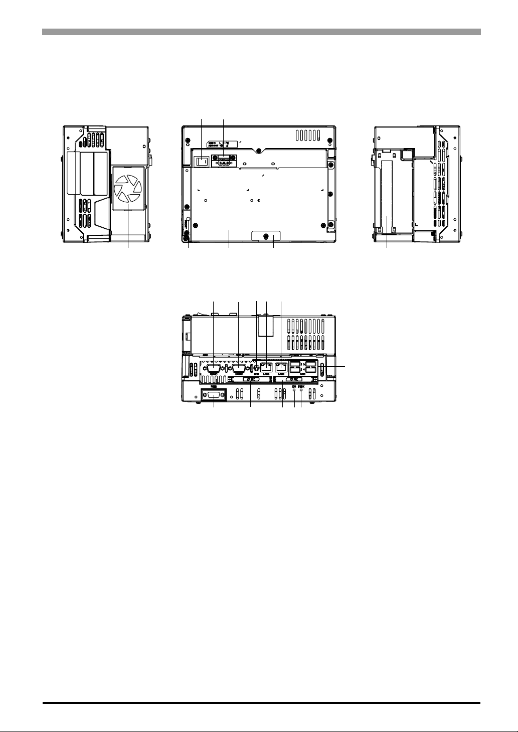
1.3 Part Names and Functions
1.3.1 PS3000-BA
A: Cooling FAN
B: Power Switch
C: Power Connector
D: Reset Switch (RESET)
Used to restart PS-B / turn on the power. Used in combination with System Set SW. Please refer to
“Switches (page 2-10)” for details.
E: Expansion Board Cover
F: Expansion Board Support
G: Expansion Unit Interface
1 port. Used to attach the PCI Unit.
H: Serial Interface (COM1)
D-sub 9-pin plug type. RS-232C.
I: Serial Interface (COM2)
D-sub 9-pin plug type. RS-232C, RS-422, RS-485 Changeover. RI/+5V Changeover.
Front
BC
Left Side Right SideTop
AD
EF G
HIJK L
PNOQR
M
PS-3000B Series Hardware Manual
1-6
J: Speaker Output Interface (SPK)
1 port. (Mini pin jack connector)
K: Ethernet Interface (LAN2)
10BASE-T/100BASE-TX/1000BASE-T Auto Changeover and Wake On LAN feature. This interface uses an
RJ-45 type modular jack connector (8 pins).
L: Ethernet Interface (LAN1)
10BASE-T/100BASE-TX Auto Changeover. This interface uses an RJ-45 type modular jack connector (8
pins).
M: USB Interface (USB)
4 ports. USB 2.0. compatible. Uses a “TYPE-A” connector.
N: Secondary CF Card Interface
Open the cover and insert the CF Card. CF Card (Type I/II-compliant) is available. IDE-type connection.*1
O: Primary CF Card Interface
Open the cover and insert the CF Card. CF Card (Type I/II-compliant) is available. IDE-type connection.*1
P: Analog RGB Interface
A mini D-sub 15 pin (socket) is used to connect a RGB monitor on the market or FP Series unit manufactured
by Pro-face.
Q: Power LED / RAS Status Lamp (ON)
R: HDD / IDE Access Lamp (DISK)
Power supply voltage 5 VDC ±5%
Output current Each port: 500mA (max.),
4 ports total: 500mA (max.)
Maximum communication
distance 5m
*1 Since an IDE-type connection is used, the unit is not hot-swappable. When inserting/removing the CF
Card, be sure that power is turned OFF.
LED PS-B Status
Green (lit) Normal Operation
(power is on)
Green (blinking) Soft OFF state
Orange (lit) System Monitor Error
RAS Error
Not lit Power is OFF
LED PS-B Status
Green (lit) Access to HDD or IDE.
Not lit Not access to HDD or IDE.
• When attaching peripheral units to the PS-B, be sure the PS-B’s power cord is
disconnected from the main power supply.

Chapter 1 Overview
1-7
1.3.2 PS3001-BD
A: Reset Switch (RESET)
Used to restart PS-B / turn on the power. Used in combination with System Set SW. Please refer to
“Switches (page 2-25)” for details.
B: Memory Slot Cover
C: Maintenance Cover
When removing this cover, you can set the switches on the PS-B’s circuit board.
D: USB Holder Attachment Area
E: Power Connector
F: Serial Interface (COM1)
RS-232C. D-sub 9-pin plug type.
G: Serial Interface (COM2)
RS-232C/RS-422/RS-485 Changeover, RI/+5V Changeover. D-sub 9-pin plug type.
H: Speaker Output Interface (SPK)
1 port. (Mini pin jack connector)
I: Ethernet Interface (LAN2)
10BASE-T/100BASE-TX/1000BASE-T Auto Changeover and Wake On LAN feature. This interface uses an
RJ-45 type modular jack connector (8 pins).
Front
H
Top
G
F J
I
E
A
LM NO
P
BCD
K
This manual suits for next models
2
Table of contents
Other Pro-face Monitor manuals

Pro-face
Pro-face GP77R Series Instruction manual

Pro-face
Pro-face GP-3750T User manual

Pro-face
Pro-face GP-4201TM User manual

Pro-face
Pro-face GP577R-TC11 User manual

Pro-face
Pro-face FP3900-T41 User manual

Pro-face
Pro-face PL-X900 Series User manual

Pro-face
Pro-face SP-5600TP User manual

Pro-face
Pro-face FP2650-T41 User manual

Pro-face
Pro-face SP5000 Series User manual

Pro-face
Pro-face GP-3600T Series User manual


