Pro-face SP5000 Series User manual


2
The information provided in this documentation contains general descriptions and/or technical
characteristics of the performance of the products contained herein. This documentation is not
intended as a substitute for and is not to be used for determining suitability or reliability of these
products for specific user applications. It is the duty of any such user or integrator to perform the
appropriate and complete risk analysis, evaluation and testing of the products with respect to the
relevant specific application or use thereof. Neither Pro-face nor any of its affiliates or subsidiaries
shall be responsible or liable for misuse of the information that is contained herein. If you have any
suggestions for improvements or amendments or have found errors in this publication, please
notify us.
No part of this document may be reproduced in any form or by any means, electronic or
mechanical, including photocopying, without express written permission of Pro-face.
All pertinent state, regional, and local safety regulations must be observed when installing and
using this product. For reasons of safety and to help ensure compliance with documented system
data, only the manufacturer should perform repairs to components.
When devices are used for applications with technical safety requirements, the relevant
instructions must be followed.
Failure to use Pro-face software or approved software with our hardware products may result in
injury, harm, or improper operating results.
Failure to observe this information can result in injury or equipment damage.
Copyright © 2015Digital Electronics Corporation. All Rights Reserved.

3
SP5000 Series Hardware Manual
Table of Contents
Safety Information . . . . . . . . . . . . . . . . . . . . . . . . . . . . . 7
About the Book. . . . . . . . . . . . . . . . . . . . . . . . . . . . . . . . 9
Chapter 1 Overview . . . . . . . . . . . . . . . . . . . . . . . . . . . . . . . . . . . . . 13
Model Number Configuration. . . . . . . . . . . . . . . . . . . . . . . . . . . . . . . . 14
Model Numbers . . . . . . . . . . . . . . . . . . . . . . . . . . . . . . . . . . . . . . . . . . 15
Package Contents . . . . . . . . . . . . . . . . . . . . . . . . . . . . . . . . . . . . . . . . 16
Certifications and Standards . . . . . . . . . . . . . . . . . . . . . . . . . . . . . . . . 18
Federal Communication Commission Radio Frequency Interference
Statement - For USA . . . . . . . . . . . . . . . . . . . . . . . . . . . . . . . . . . . . . . 20
Hazardous Location Installation - For USA and Canada. . . . . . . . . . . 21
European (CE) Compliance. . . . . . . . . . . . . . . . . . . . . . . . . . . . . . . . . 23
KC Markings . . . . . . . . . . . . . . . . . . . . . . . . . . . . . . . . . . . . . . . . . . . . 24
Wireless LAN Information . . . . . . . . . . . . . . . . . . . . . . . . . . . . . . . . . . 25
Chapter 2 Device Connectivity . . . . . . . . . . . . . . . . . . . . . . . . . . . . 31
System Design . . . . . . . . . . . . . . . . . . . . . . . . . . . . . . . . . . . . . . . . . . 32
Accessories . . . . . . . . . . . . . . . . . . . . . . . . . . . . . . . . . . . . . . . . . . . . . 34
Chapter 3 Parts Identification and Functions . . . . . . . . . . . . . . . . 39
3.1 Box Module . . . . . . . . . . . . . . . . . . . . . . . . . . . . . . . . . . . . . . . . . . . . . 40
Power Box . . . . . . . . . . . . . . . . . . . . . . . . . . . . . . . . . . . . . . . . . . . . . . 41
Open Box. . . . . . . . . . . . . . . . . . . . . . . . . . . . . . . . . . . . . . . . . . . . . . . 43
LED Indications . . . . . . . . . . . . . . . . . . . . . . . . . . . . . . . . . . . . . . . . . . 45
3.2 Display Module . . . . . . . . . . . . . . . . . . . . . . . . . . . . . . . . . . . . . . . . . . 46
Premium Display . . . . . . . . . . . . . . . . . . . . . . . . . . . . . . . . . . . . . . . . . 47
Advanced Display . . . . . . . . . . . . . . . . . . . . . . . . . . . . . . . . . . . . . . . . 50
LED Indications . . . . . . . . . . . . . . . . . . . . . . . . . . . . . . . . . . . . . . . . . . 53
Chapter 4 Specifications . . . . . . . . . . . . . . . . . . . . . . . . . . . . . . . . . 55
4.1 General Specifications. . . . . . . . . . . . . . . . . . . . . . . . . . . . . . . . . . . . . 56
Electrical Specifications. . . . . . . . . . . . . . . . . . . . . . . . . . . . . . . . . . . . 57
Environmental Specifications . . . . . . . . . . . . . . . . . . . . . . . . . . . . . . . 59
Structural Specifications . . . . . . . . . . . . . . . . . . . . . . . . . . . . . . . . . . . 60
4.2 Functional Specifications . . . . . . . . . . . . . . . . . . . . . . . . . . . . . . . . . . . 63
Display Specifications . . . . . . . . . . . . . . . . . . . . . . . . . . . . . . . . . . . . . 64
Memory . . . . . . . . . . . . . . . . . . . . . . . . . . . . . . . . . . . . . . . . . . . . . . . . 65
Clock . . . . . . . . . . . . . . . . . . . . . . . . . . . . . . . . . . . . . . . . . . . . . . . . . . 66
Touch Panel . . . . . . . . . . . . . . . . . . . . . . . . . . . . . . . . . . . . . . . . . . . . 67
4.3 Interface Specifications . . . . . . . . . . . . . . . . . . . . . . . . . . . . . . . . . . . . 68
Interface Specifications . . . . . . . . . . . . . . . . . . . . . . . . . . . . . . . . . . . . 69
Interface Connection . . . . . . . . . . . . . . . . . . . . . . . . . . . . . . . . . . . . . . 71
Serial Interface (RS-232C and RS-422/RS-485) for COM1/COM2. . . 74
Auxiliary Output/Speaker Output Interface (AUX) . . . . . . . . . . . . . . . . 76
DVI-D Output Interface (for SP-5B40) . . . . . . . . . . . . . . . . . . . . . . . . . 77

4
Chapter 5 Dimensions . . . . . . . . . . . . . . . . . . . . . . . . . . . . . . . . . . . 79
5.1 Power Box . . . . . . . . . . . . . . . . . . . . . . . . . . . . . . . . . . . . . . . . . . . . . . 80
SP-5B10 . . . . . . . . . . . . . . . . . . . . . . . . . . . . . . . . . . . . . . . . . . . . . . . 80
5.2 Open Box. . . . . . . . . . . . . . . . . . . . . . . . . . . . . . . . . . . . . . . . . . . . . . . 81
SP-5B40 . . . . . . . . . . . . . . . . . . . . . . . . . . . . . . . . . . . . . . . . . . . . . . . 81
5.3 Premium Display . . . . . . . . . . . . . . . . . . . . . . . . . . . . . . . . . . . . . . . . . 82
SP-5500TP . . . . . . . . . . . . . . . . . . . . . . . . . . . . . . . . . . . . . . . . . . . . . 83
SP-5600TP/SP-5660TP . . . . . . . . . . . . . . . . . . . . . . . . . . . . . . . . . . . 84
SP-5700TP . . . . . . . . . . . . . . . . . . . . . . . . . . . . . . . . . . . . . . . . . . . . . 85
5.4 Advanced Display . . . . . . . . . . . . . . . . . . . . . . . . . . . . . . . . . . . . . . . . 86
SP-5400WA. . . . . . . . . . . . . . . . . . . . . . . . . . . . . . . . . . . . . . . . . . . . . 87
SP-5500WA. . . . . . . . . . . . . . . . . . . . . . . . . . . . . . . . . . . . . . . . . . . . . 88
SP-5600WA. . . . . . . . . . . . . . . . . . . . . . . . . . . . . . . . . . . . . . . . . . . . . 89
5.5 Box and Display Modules - Combined Dimensions. . . . . . . . . . . . . . . 90
SP-5500TP with Box Module. . . . . . . . . . . . . . . . . . . . . . . . . . . . . . . . 91
SP-5600TP/SP-5660TP with Box Module . . . . . . . . . . . . . . . . . . . . . . 93
SP-5700TP with Box Module. . . . . . . . . . . . . . . . . . . . . . . . . . . . . . . . 95
SP-5400WA with Box Module . . . . . . . . . . . . . . . . . . . . . . . . . . . . . . . 97
SP-5500WA with Box Module . . . . . . . . . . . . . . . . . . . . . . . . . . . . . . . 99
SP-5600WA with Box Module . . . . . . . . . . . . . . . . . . . . . . . . . . . . . . . 101
Chapter 6 Installation and Wiring . . . . . . . . . . . . . . . . . . . . . . . . . . 103
6.1 Installation . . . . . . . . . . . . . . . . . . . . . . . . . . . . . . . . . . . . . . . . . . . . . . 104
Installation Procedures . . . . . . . . . . . . . . . . . . . . . . . . . . . . . . . . . . . . 104
6.2 Wiring Principles . . . . . . . . . . . . . . . . . . . . . . . . . . . . . . . . . . . . . . . . . 117
Connecting the DC Power Cord . . . . . . . . . . . . . . . . . . . . . . . . . . . . . 118
Connecting the Power Supply . . . . . . . . . . . . . . . . . . . . . . . . . . . . . . . 121
Grounding . . . . . . . . . . . . . . . . . . . . . . . . . . . . . . . . . . . . . . . . . . . . . . 123
6.3 USB Cable Clamp . . . . . . . . . . . . . . . . . . . . . . . . . . . . . . . . . . . . . . . . 124
USB Cable Clamp Type A (1 port) . . . . . . . . . . . . . . . . . . . . . . . . . . . 125
USB Clamp mini-B (1 port) . . . . . . . . . . . . . . . . . . . . . . . . . . . . . . . . . 128
6.4 AUX Connector . . . . . . . . . . . . . . . . . . . . . . . . . . . . . . . . . . . . . . . . . . 130
Introduction . . . . . . . . . . . . . . . . . . . . . . . . . . . . . . . . . . . . . . . . . . . . . 130
6.5 SD Card Insertion/Removal. . . . . . . . . . . . . . . . . . . . . . . . . . . . . . . . . 131
Introduction . . . . . . . . . . . . . . . . . . . . . . . . . . . . . . . . . . . . . . . . . . . . . 132
Inserting the SD Card . . . . . . . . . . . . . . . . . . . . . . . . . . . . . . . . . . . . . 133
Removing the SD Card . . . . . . . . . . . . . . . . . . . . . . . . . . . . . . . . . . . . 134
SD Card Data Backup . . . . . . . . . . . . . . . . . . . . . . . . . . . . . . . . . . . . . 135
6.6 CFast Card Insertion/Removal . . . . . . . . . . . . . . . . . . . . . . . . . . . . . . 136
Introduction . . . . . . . . . . . . . . . . . . . . . . . . . . . . . . . . . . . . . . . . . . . . . 137
Inserting the CFast Card . . . . . . . . . . . . . . . . . . . . . . . . . . . . . . . . . . . 138
Removing the CFast Card . . . . . . . . . . . . . . . . . . . . . . . . . . . . . . . . . . 139
CFast Card Data Backup. . . . . . . . . . . . . . . . . . . . . . . . . . . . . . . . . . . 140
6.7 Front USB Cover . . . . . . . . . . . . . . . . . . . . . . . . . . . . . . . . . . . . . . . . . 141
Opening the Front USB Cover. . . . . . . . . . . . . . . . . . . . . . . . . . . . . . . 141
6.8 Isolation Unit and USB/RS-422/485 Conversion Adapter . . . . . . . . . . 143
Introduction . . . . . . . . . . . . . . . . . . . . . . . . . . . . . . . . . . . . . . . . . . . . . 144
Installing to the Box Module . . . . . . . . . . . . . . . . . . . . . . . . . . . . . . . . 145

SP5000 Series Hardware Manual
5
Chapter 7 Maintenance . . . . . . . . . . . . . . . . . . . . . . . . . . . . . . . . . . 147
Regular Cleaning . . . . . . . . . . . . . . . . . . . . . . . . . . . . . . . . . . . . . . . . . 148
Periodic Check Points . . . . . . . . . . . . . . . . . . . . . . . . . . . . . . . . . . . . . 149
Replacing the Installation Gasket. . . . . . . . . . . . . . . . . . . . . . . . . . . . . 150
Replacing the Primary Battery . . . . . . . . . . . . . . . . . . . . . . . . . . . . . . . 151
Replacing the System Card (SD Card) . . . . . . . . . . . . . . . . . . . . . . . . 154
Replacing the System Card (CFast Card) . . . . . . . . . . . . . . . . . . . . . . 156
Replacing the Backlight . . . . . . . . . . . . . . . . . . . . . . . . . . . . . . . . . . . . 159
After-sales Service . . . . . . . . . . . . . . . . . . . . . . . . . . . . . . . . . . . . . . . . 160

6

7
SP5000 Series Hardware Manual
Safety Information
Important Information
NOTICE
Read these instructions carefully, and look at the equipment to become familiar with the device
before trying to install, operate, or maintain it. The following special messages may appear
throughout this documentation or on the equipment to warn of potential hazards or to call attention
to information that clarifies or simplifies a procedure.
PLEASE NOTE
Electrical equipment should be installed, operated, serviced, and maintained only by qualified
personnel. No responsibility is assumed by Pro-face for any consequences arising out of the use
of this material.
A qualified person is one who has skills and knowledge related to the construction and operation
of electrical equipment and its installation, and has received safety training to recognize and avoid
the hazards involved.

8

9
SP5000 Series Hardware Manual
About the Book
At a Glance
Document Scope
This manual describes how to use this product.
Validity Note
This documentation is valid for this product.
The technical characteristics of the device(s) described in this manual also appear online at
http://www.pro-face.com/otasuke/.
The characteristics presented in this manual should be the same as those that appear online. In
line with our policy of constant improvement we may revise content over time to improve clarity and
accuracy. In the event that you see a difference between the manual and online information, use
the online information as your reference.
Registered Trademarks
Microsoft and Windows are registered trademarks of Microsoft Corporation in the United States
and/or other countries.
Product names used in this manual may be the registered trademarks owned by the respective
proprietors.
Related Documents
You can download the manuals related to this product, such as the software manual, from our
website “Otasuke Pro” at http://www.pro-face.com/otasuke/.
Product Related Information
Critical alarm indicators and system functions require independent and redundant protection
hardware and/or mechanical interlocks.
When you cycle power, wait at least 10 seconds after it has been turned off. If this product is
restarted too quickly, it may not operate correctly.
DANGER
HAZARD OF ELECTRIC SHOCK, EXPLOSION, OR ARC FLASH
Remove all power from the device before removing any covers or elements of the system, and
prior to installing or removing any accessories, hardware, or cables.
Unplug the power cable from both this product and the power supply.
Always use a properly rated voltage sensing device to confirm power is off.
Replace and secure all covers or elements of the system before applying power to this
product.
Use only the specified voltage when operating this product. The DC unit is designed to use 12
to 24 Vdc. Always check whether your device is DC powered before applying power.
Failure to follow these instructions will result in death or serious injury.
10
In the event the screen cannot be properly read, for example, if the backlight is not functioning, it
may be difficult or impossible to identify a function. Functions that may present a hazard if not
immediately executed, such as a fuel shut-off, must be provided independently of this product. The
machine’s control system design must take into account the possibility of the backlight no longer
functioning and the operator being unable to control the machine or making mistakes in the control
of the machine.
For additional information, refer to NEMA ICS 1.1 (latest edition), "Safety Guidelines for the
Application, Installation, and Maintenance of Solid State Control" and to NEMA ICS 7.1 (latest
edition), "Safety Standards for Construction and Guide for Selection, Installation and Operation of
Adjustable-Speed Drive Systems" or their equivalent governing your particular location.
NOTE: Open Box is a highly configurable device and is not based on a real-time operating system.
Changes to the software and settings of the following must be considered new implementations as
discussed in the previous warning messages. Examples of such changes include:
System BIOS
Operating System
Installed hardware
Installed software
WARNING
LOSS OF CONTROL
The designer of any control scheme must consider the potential failure modes of control paths
and, for certain critical control functions, provide a means to achieve a safe state during and
after a path failure. Examples of critical control functions are emergency stop and overtravel
stop, power outage and restart.
Separate or redundant control paths must be provided for critical control functions.
System control paths may include communication links. Consideration must be given to the
implications of unanticipated transmission delays or failures of the link.
Observe all accident prevention regulations and local safety guidelines.
Each implementation of this product must be individually and thoroughly tested for proper
operation before being placed into service.
The machine control system design must take into account the possibility of the backlight no
longer functioning and the operator being unable to control the machine, or making errors in
the control of the machine.
Failure to follow these instructions can result in death, serious injury, or equipment
damage.
WARNING
UNINTENDED EQUIPMENT OPERATION
The application of this product requires expertise in the design and programming of control
systems. Only persons with such expertise should be allowed to program, install, alter, and apply
this product.
Follow all local and national safety standards.
Failure to follow these instructions can result in death, serious injury, or equipment
damage.
SP5000 Series Hardware Manual
11
The following characteristics are specific to the LCD panel and are considered normal behavior:
LCD screen may show unevenness in the brightness of certain images or may appear different
when seen from outside the specified viewing angle. Extended shadows, or crosstalk may also
appear on the sides of screen images.
LCD screen pixels may contain black and white colored spots and color display may seem to
have changed.
When the same image is displayed on the screen for a long period, an afterimage may appear
when the image is changed.
The panel brightness may decrease when used for a long time in an environment continuously
filled with inert gas. To prevent deterioration of panel brightness, regularly ventilate the panel.
For more information, please contact your local distributor.
http://www.pro-face.com/trans/en/manual/1015.html
NOTE: Change the screen image periodically and try not to display the same image for a long
period of time.
WARNING
UNINTENDED EQUIPMENT OPERATION
Do not use this product as the only means of control for critical system functions such as motor
start/stop or power control.
Do not use this equipment as the only notification device for critical alarms, such as device
overheating or overcurrent.
Use only the software provided with this product. If you use another software, please confirm
the operation and safety before use.
Failure to follow these instructions can result in death, serious injury, or equipment
damage.
CAUTION
SERIOUS EYE AND SKIN INJURY
The liquid in the LCD panel contains an irritant:
Avoid direct skin contact with the liquid.
Wear gloves when you handle a broken or leaking unit.
Do not use sharp objects or tools in the vicinity of the LCD panel.
Handle the LCD panel carefully to prevent puncture, bursting, or cracking of the panel material.
If the panel is damaged and any liquid comes in contact with your skin, immediately rinse the
area with running water for at least 15 minutes. If the liquid gets in your eyes, immediately rinse
your eyes with running water for at least 15 minutes and consult a doctor.
Failure to follow these instructions can result in injury or equipment damage.

12

13
SP5000 Series Hardware Manual
SP5000 Seri es Hardware M anual
Overview
ZenzaiHar dwareMan ual_SP500 0 10/2014
Overview
Chapter 1
Overview
What Is in This Chapter?
This chapter contains the following topics:
Topic Page
Model Number Configuration 14
Model Numbers 15
Package Contents 16
Certifications and Standards 18
Federal Communication Commission Radio Frequency Interference Statement - For USA 20
Hazardous Location Installation - For USA and Canada 21
European (CE) Compliance 23
KC Markings 24
Wireless LAN Information 25

Overview
14
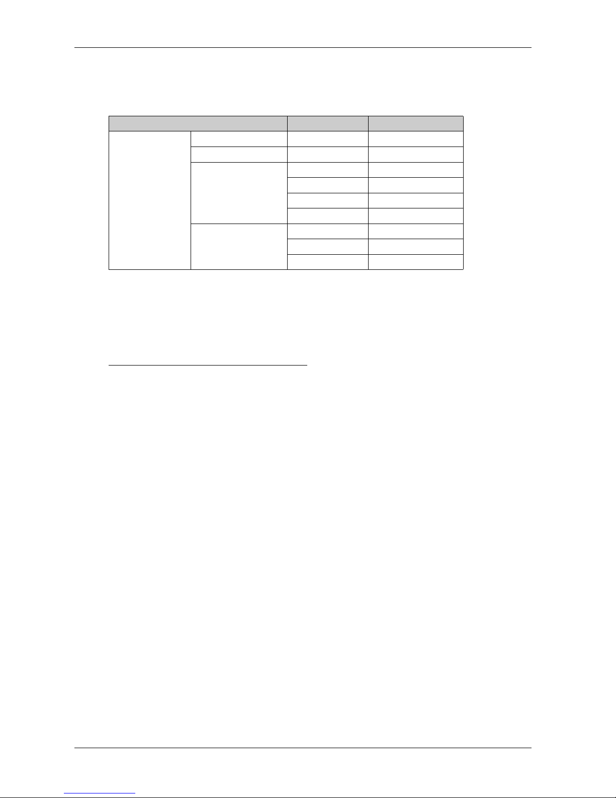
Model Number Configuration
The following describes the configuration of model numbers.
Box Module
Display Module
Digit Position 1 2 3 4 5 6 7 8 9
P F X (model) (series) (-) (class)
SP 5 B: BOX 10: Power
40: Open
Digit Position 1 2 3 4 5 6 7 8 9 10 11 12
P F X (model) (series) (size) ( type) (LCD) (touch
panel)
(power
supply)
SP 5 4: 7"
5: 10.1"/
10.4"
6: 12.1"
7: 15"
00: Normal
60: Wireless
LAN
T: TFT
W: Wide
TFT
A: Analog
P: Multi
D: DC
SP5000 Series Hardware Manual
15
Model Numbers
NOTE: You can connect any Display Module to any Box Module.
Global Code
A global code is assigned to every Pro-face product as a universal model number. For more
information on product models and their matching global codes, please refer to the following URL.
http://www.pro-face.com/product/globalcode.html
Series Model Names Model Numbers
SP5000 Series Power Box SP-5B10 PFXSP5B10
Open Box SP-5B40 PFXSP5B40
Premium Display SP-5500TP PFXSP5500TPD
SP-5600TP PFXSP5600TPD
SP-5660TP PFXSP5660TPD
SP-5700TP PFXSP5700TPD
Advanced Display SP-5400WA PFXSP5400WAD
SP-5500WA PFXSP5500WAD
SP-5600WA PFXSP5600WAD

Overview
16
Package Contents
NOTE: This product has been carefully packed with special attention to quality. However, should
you find anything damaged or missing, please contact your local distributor immediately.
Box Module
Verify all items listed here are present in your package:
1 SP5000 Series Box Module: 1
2 USB Clamp Type A (1 port): 2 sets for Power Box, 3 sets for Open Box (1 clip and 1 tie)
3 SP5000 Series (Box Module) Installation Guide: 1
4 Warning/Caution Information: 1
5 End-user License Agreement (only for Open Box): 2
Display Module
Verify all items listed here are present in your package:
1 SP5000 Series Display Module: 1
2 Installation Gasket: 1 (attached to this product)
3 DC Power Supply Connector (Right-angle*1): 1
4 SP5000 Series (Display Module) Installation Guide: 1
5 Warning/Caution Information: 1
*1 Straight type for SP-5400WA

SP5000 Series Hardware Manual
17
Revision
You can identify the product version (PV), revision level (RL), and the software version (SV) from
the product level.

Overview
18
Certifications and Standards
NOTE: Some products are not subject to certification and standards. And some products have not
received their certification and standards but are scheduled for assessment.
For information on certifications and standards, such as certified models and certificates, see the
product markings or the following URL.
http://www.pro-face.com/worldwide.html
Agency Certifications
Pro-face submitted this product for independent testing and qualification by third-party listing
agencies. These agencies have certified this product as meeting the following standards.
Underwriters Laboratories Inc., UL 508 and CSA C22.2 No142, Industrial Control Equipment
Underwriters Laboratories Inc., ANSI/ISA 12.12.01 and CSA C22.2 No213, Electrical
Equipment for Use in Class I, Division 2 Hazardous (Classified) Locations
IECEx / ATEX for use in zones 2/22
GOST-R or EAC certification (Russia, Belarus, Kazakhstan)
American Bureau of Shipping (ABS)
Bureau Veritas (BV)
China Classification Society (CCS)
Det Norske Veritas (DNV)
Germanischer Lloyd (GL)
Lloyd’s Register (LR)
Registro Italiano Navale (RINA)
Nippon Kaiji Kyokai (NK)
Compliance Standards
Europe:
CE
Directive 2006/95/EC (Low Voltage)
Directive 2004/108/EC (EMC)
Programmable Controllers: EN 61131-2 (ED 3)
EN61000-6-4
EN61000-6-2
Directive 94/9/EC (ATEX)
EN60079-0
EN60079-15
EN60079-31
Directive 1995/5/EC (RTTE)
EN300 328
EN301 489
EN60950-1
Australia
RCM
EN61000-6-4
Korea
KC
KN11
KN61000-4 series

SP5000 Series Hardware Manual
19
Qualifications Standards
Pro-face voluntarily tested this product to additional standards. The additional tests performed, and
the standards under which the tests were conducted, are specifically identified in Structural
Specifications (see page 60).
Hazardous Substances
This product is a device for use in factory systems. When using this product in a system, the system
should comply with the following standards in regards to the installation environment and handling:
WEEE, Directive 2012/19/EU
RoHS, Directive 2011/65/EU
RoHS China, Standard SJ/T 11363-2006
REACH regulation EC 1907/2006

Overview
20
Federal Communication Commission Radio Frequency Interference Statement -
For USA
FCC Radio Interference Information
This product has been tested and found to comply with the Federal Communications Commission
(FCC) limits for a Class A digital device, pursuant to Part 15 of the FCC Rules. These limits are
designed to provide reasonable protection against harmful interference in a commercial, industrial
or business environment. This product generates, uses, and can radiate radio frequency energy
and, if not installed and used in accordance with the instructions, may cause or be subject to
interference with radio communications. To minimize the possibility of electromagnetic interference
in your application, observe the following two rules:
Install and operate this product in such a manner that it does not radiate sufficient
electromagnetic energy to cause interference in nearby devices.
Install and test this product to ensure that the electromagnetic energy generated by nearby
devices does not interfere with the operation of this product.
Changes or modifications not expressly approved by the party responsible for compliance could
void the user’s authority to operate this product.
WARNING
ELECTROMAGNETIC / RADIO INTERFERENCE
Electromagnetic radiation may disrupt the operation of this product leading to unintended
equipment operation. If electromagnetic interference is detected:
Increase the distance between this product and the interfering equipment.
Reorient this product and the interfering equipment.
Reroute power and communication lines to this product and the interfering equipment.
Connect this product and the interfering equipment to different power supplies.
Always use shielded cables when connecting this product to a peripheral device or another
computer.
Failure to follow these instructions can result in death, serious injury, or equipment
damage.
Other manuals for SP5000 Series
1
Table of contents
Other Pro-face Monitor manuals

Pro-face
Pro-face FP2650-T41 User manual

Pro-face
Pro-face PS-3000B Series User manual

Pro-face
Pro-face SP-5600TP User manual

Pro-face
Pro-face GP-3600T Series User manual

Pro-face
Pro-face GP577R-TC11 User manual

Pro-face
Pro-face FP3650-T41 User manual

Pro-face
Pro-face GP77R Series Instruction manual

Pro-face
Pro-face Xycom SXT1811 Installation instructions

Pro-face
Pro-face GC4000 Series User manual

Pro-face
Pro-face PL-X900 Series User manual


