Pro-face FP2650-T41 User manual
• Prior to connecting the FP2650-T41 (hereafter referred to as the "FP" or "FP unit")
unit's power cord terminals to the Terminal Block, be sure to check that the FP unit's
power supply is completely turned OFF, via a breaker, or similar unit.
• Whenever changing the backlight be sure to unplug the FP unit's power cord and
wear protective gloves to prevent electric shocks and burns.
• Do not open or remodel the FP unit. Doing so may lead to a fire or electric shock.
• Do not use voltage levels that exceed the FP unit's specified voltage range. Doing so
may cause a fire or an electric shock.
• Do not use the FP in an environment where flammable gases are present, since
operating the FP may cause an explosion.
• Do not use the FP as a warning device for critical alarms that can cause serious
operator injury, machine damage or production stoppage. Critical alarm indicators
and their control/activator units must be designed using stand-alone hardware and/
or mechanical interlocks.
• Do not use FP unit touch panel switches in human-safety-related or important disas-
ter prevention situations. For safety-related switches, such as an emergency stop
switch, be sure to use a separately installed mechanical switch.
• After the FP unit’s backlight burns out, unlike “Standby Mode”, the unit's touch panel
is still active. If the operator fails to notice that the backlight is burned out and
touches the panel, a potentially dangerous machine operation error can occur.
Therefore, do not use FP unit touch-screen switches for the control of equipment
safety mechanisms, such as Emergency Stop switches, etc. that protect humans
from injury and equipment from damage.
If your FP unit's backlight suddenly turns OFF, use the following steps to determine
if the backlight is actually burned out.
1) If your currently running FP application is not set to turn the backlight OFF, and
the screen has gone blank, your backlight is burned out.
2) If your current FP application is set to turn the backlight OFF, if touching a corner of
the screen does not cause the display to reappear, your backlight is burned out.
• To prevent operator injury or machine damage, be sure to design your machine
operation system so that the machine will not malfunction due to a communication
fault between the FP unit and its host controller.
• Do not use the FP with aircraft control devices, aerospace equipment, central trunk
data transmission (communication) devices, nuclear power control devices, or medical
life support equipment, due to these devices' inherent requirements of extremely
high levels of safety and reliability.
• When using the FP with transportation vehicles (trains, cars and ships), disaster
and crime prevention devices, various types of safety equipment, non-life support
related medical devices and others, be sure to use redundant and/or failsafe system
designs to ensure the appropriate degree of system reliability and safety.
WARNINGS
FP2650-T41
Installation Guide

To prevent this unit from malfunctioning:
• Do not strike the FP unit's touch panel with a hard or heavy object, or press on the
touch panel with too much force, since it may damage the display.
• Do not install the FP where the temperature will exceed the specified range.
• Be sure that water, liquids or metal particles do not enter the FP, since it may cause a
malfunction or a short circuit.
• Do not install the FP where sudden, large changes in temperature may occur. These
changes may cause condensation to form inside the unit, possibly leading to a mal-
function.
• To prevent excessive heat from building up inside the unit, do not install the FP where
its ventilation holes may be blocked. Also, do not install or store the FP near high
temperature equipment.
• Do not install or store the FP where direct sunlight or high levels of dust exist.
• Since the FP is a precision instrument, do not install or store it where either strong
shocks or excessive vibration may occur.
• Do not install or store the FP in an area containing chemicals or chemical fumes.
• Do not use paint thinner or organic solvents to clean the FP unit's case or screen.
• After turning the FP OFF, be sure to wait a few seconds before turning it ON again. If
the FP is started too soon, it may not start up correctly.

FP2650-T41 unit is UL/c-UL(CSA) qualified product (UL File No. E171486).
FP2650-T41 (UL Registration Model No.:3384101-01)
The FP conforms to the following standards:
UL60950-1 First Edition
(Information Technology Equipment - Safety - Part 1: General Requirements)
CAN/CSA-C22.2 No.60950-1-03 (c-UL Qualification)
(Information Technology Equipment - Safety - Part 1: General Requirements)
<Cautions>
Be aware of the following items when applying for UL/CSA about the end-use product which the FP is
builtinto.
• The FP unit's rear face is not approved as an enclosure. When building the FP unit into an end-use
product, be sure to use an enclosure that satisfies required standards as the end-use product's overall
enclosure.
• The FP unit must be used indoors only.
• This unit should be installed in the front face of a metal panel.
• If the FP unit is installed so as to cool itself naturally, be sure to install it in a vertical panel. Also, be
sure that the FP unit is installed at least 100 mm away from any adjacent structures or machine
parts. If these conditions are not met, the heat generated by the FP unit's internal components may
cause the unit to fail to meet UL standard.
• The end-use product, the FP is built into, should be examined about compatibility of combination
with the FP by UL.
UL/c-UL/CSA Application Notes
The FP2650-T41 unit is a CE marked product that conforms to EMC directives.
<Complies with the following Standards>
• Safety
EN60950-1
• EMI
EN55011 (Group 1, Class A)
• EMS <EN61000-6-2>
EN61000-4-2, EN61000-4-3, EN61000-4-4, EN61000-4-5, EN61000-4-6, EN61000-4-11
If the following requirements are not met, the FP may fail to meet EN60950-1 standard require-
ments.
• The FP must be used as a built-in component of an end-use product.
• The FP unit must be used indoors only.
• When using the FP in an end-use product, be sure to install the FP unit’s power cut-off switch
where the operator can easily reach it. Use the switch that is appropriate for the current and
voltage used.
• The end-use product, the FP is built into, shoud be used with a UL60950-1 compatible structure.
CE Marking Notes
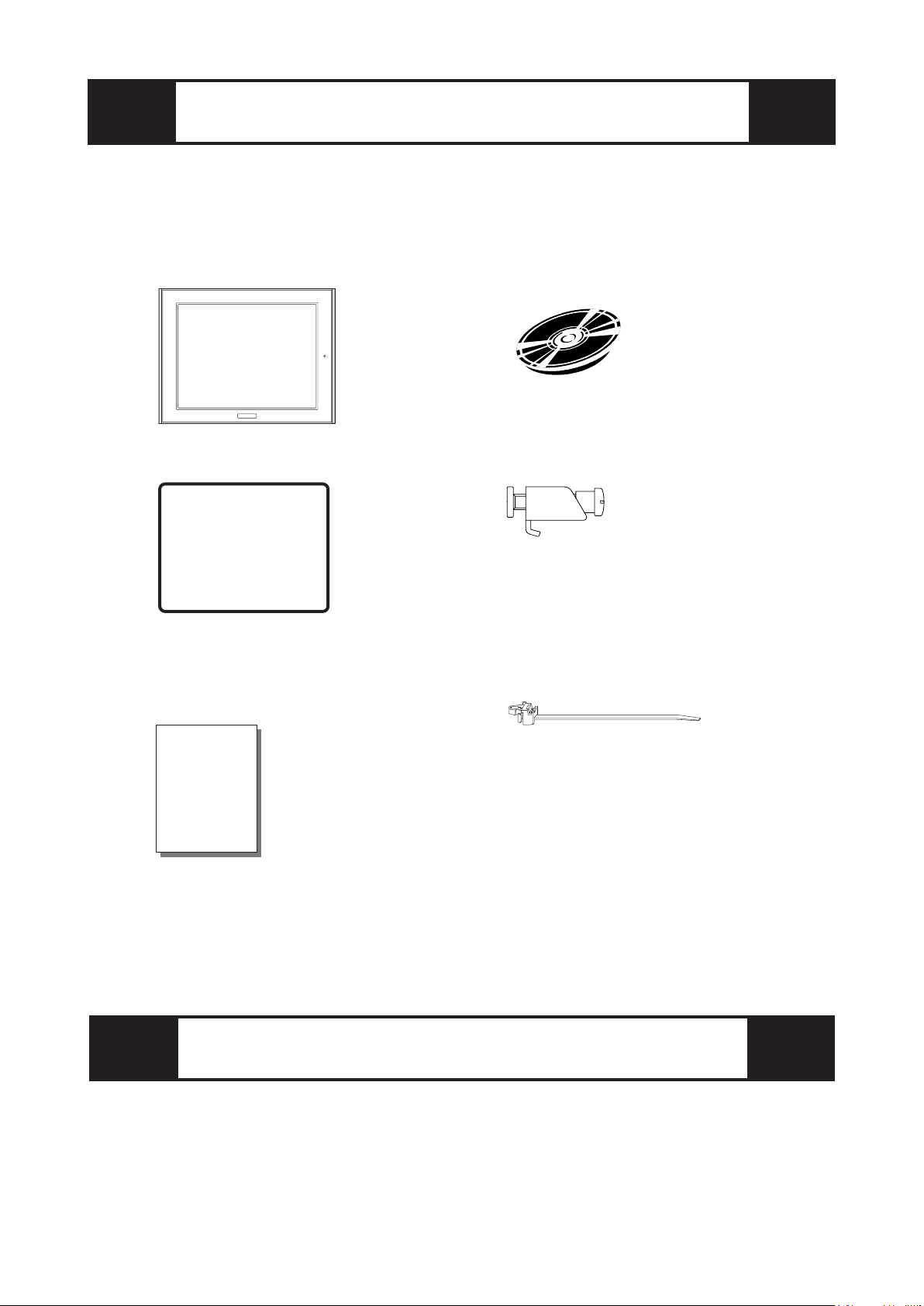
The following items are included in the FP unit's package. Before using the
FP, please confirm that all items listed here are present.
This unit has been carefully packed, with special attention to quality. How-
ever, should you find anything damaged or missing, please contact your
local FP distributor immediately.
Package Contents
FP unit CD-ROM (1)
(FP2650-T41) (FP2650-T41 Series User Manual)
Installation Gasket (1) Installation Brackets (4/set)
FP2650-T41 Installation Guide (1) USB Cable Strap (1)
(this manual)
Options
Cables
Touch Panel Driver Software
Maintenance Parts
Installation
Guide
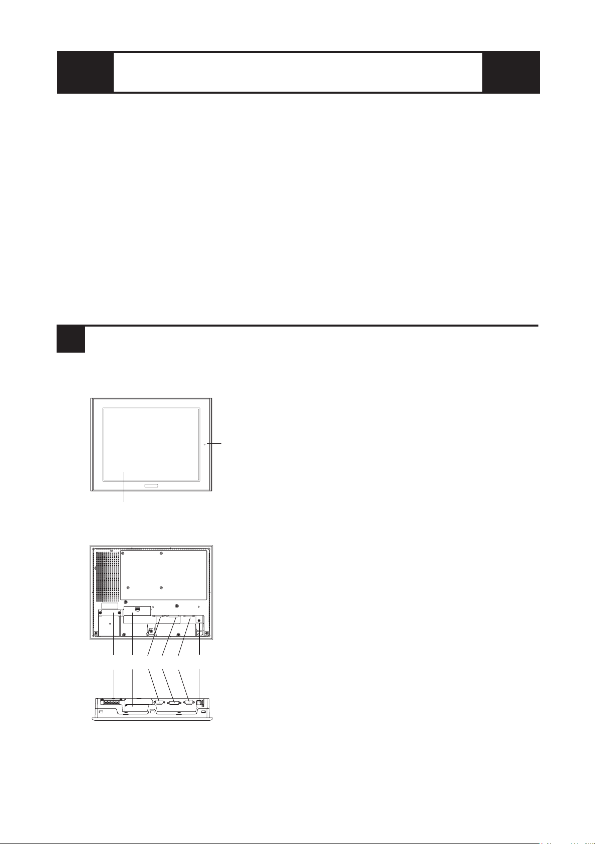
1Part Names
A: TFT Color LCD
Displays host data.
B: Touch Panel
Switches screens or writes/sends data to the host.
C: Power Input Terminal Block
Provides power to the FP unit via the input and ground
terminals.
D: Dip Switch Cover
Covers the FP unit's operation mode dip switches.
E: Analog RGB Interface Connector
Connector for analog RGB cable.
F: DVI-D Interface Connector
Connector for DVI-D cable.
G: RS-232C Interface Connector
Connector for RS-232C (serial) cable. Used for
sending touch panel data to the host, and receiving
commands from the host.
H: USB Interface Connector
Connector for USB cable. Used for sending touch panel
data to the host, and receiving commands from the host.
I: Front LED
Used to indicate power supply, backlight or image
signal input status.
Front View
Rear View
A, B
I
Bottom View
C D E F G H
The FP2650-T41 unit's PDF manual file (fp2650e) is contained in the CD-ROM's
[Manual\Eng] folder.
Reading a PDF file requires installation of the Adobe Corporation's Acrobat®Reader.
Acrobat®Reader Installation:
To install the Acrobat®Reader software, follow the steps given below.
1) This software, in the form of a self-extracting file, is located in this CD-ROM in the
folder titled [reader]. Use the Explorer software to find the file [Reader\Eng\
ar505enu.exe], and double-click on the file icon to begin the Reader installation.
2) After installation begins, follow the instructions given.
Acrobat® Reader Copyright© Adobe Systems Incorporated. All rights reserved.
About The Manual

2Dimensions
FP2650-T41
Unit:mm [in]
Front View
301 [11.85]
227 [8.94]
243 [9.57]
317 [12.48] 58 [2.28]
Top View
8 [0.31]
Side View

3Dip Switches
The FP unit's dip switches are located behind the Dip Switch Cover.
Dip switch setting are effective only when starting up the FP unit.
After changing any dip switch settings, be sure to restart your FP unit.
SW
No. Function Description Factory
Settings
1-1
Switch between USB
and RS-232C for touch
panel data transmission.
Used to set the touch panel data input (command
control) method to either USB or RS-232C.
ON : USB
OFF : RS-232C (Default setting)
1-2 Display/hide the OSD.
Used to display or hide the OSD.
ON : Hide
OFF : Display (Default setting)
1-3
1-4
1-5 Switch between analog
RGB and DVI-D input.
Used to change the image input method.
ON : DVI-D
OFF : analog RGB (Default setting)
1-6
1-7
1-8
All OFF
Reserved Set this switch to OFF
Reserved Be sure these switches are always set to OFF
ON
SW1 86543271
Bottom View
4Interfaces
Analog RGB Interface
Input Signal Type Analog RGB
Input Signal Characteristics
Image signal: analog RGB
Synchronous signal: TTL level, negative true or positive true
Scanning type: non-interlace
OSD Settings
(On Screen Display)
CONTRAST
BLACK LEVEL
H-POS
V-POS
H-SIZE
PHASE
BACKLIGHT
DEFAULT (ALL CLEAR)
Connector: Mini Dsub 15 pin male
Connector set screw: Inch type (4-40)
Analog RGB Cable: FP-CV02-45 (VGA standard)
(Manufactured by Digital Electronics Corporation of Japan)
If a cable other than the specified Analog RGB cable is used, FP unit
operation cannot be guaranteed due to the possibility of noise
interference.
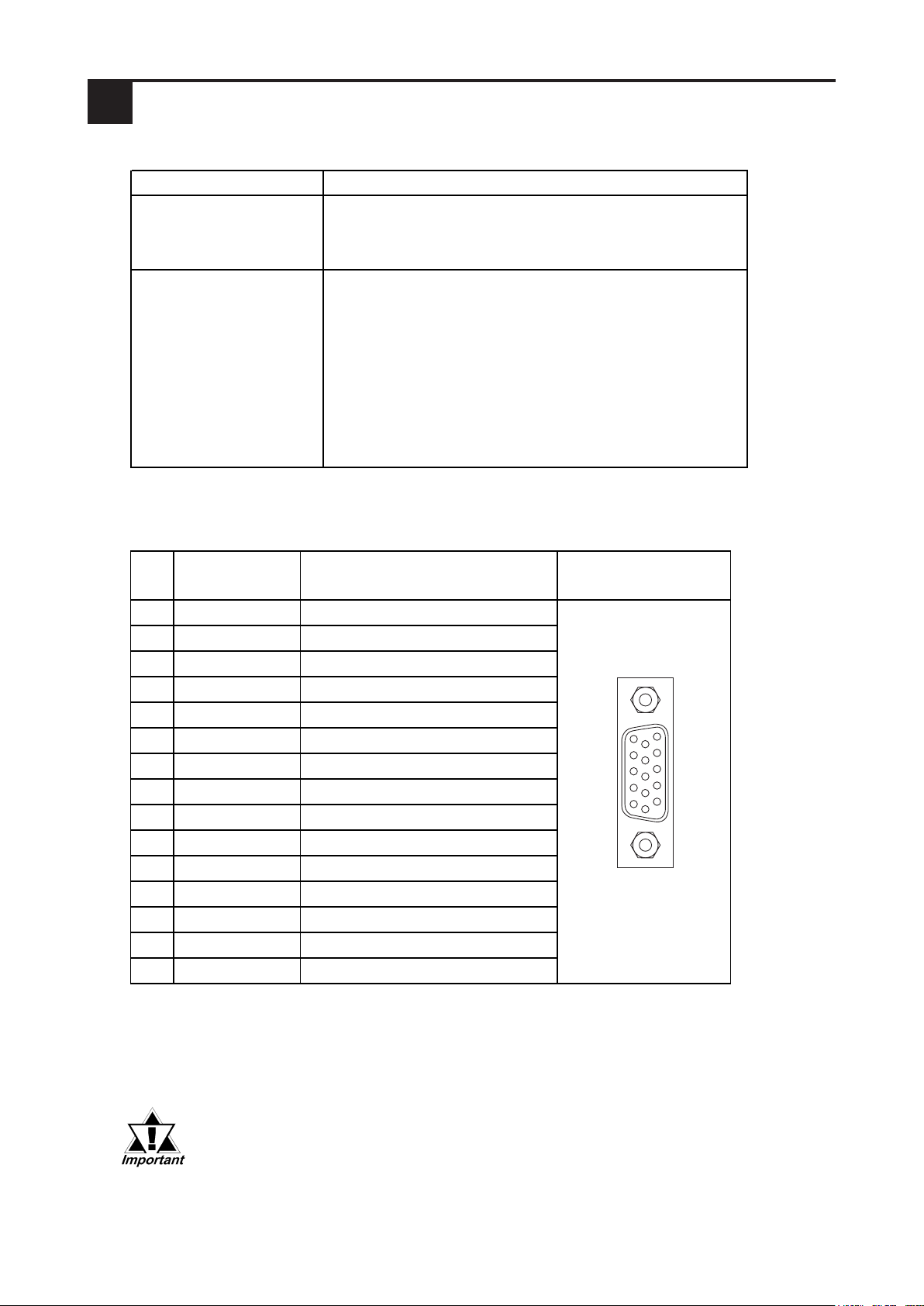
Pin Assignments and Signal Names for Analog RGB
Pin
No. Signal Name Condition Pin Location
1 Analog R R signal input
2 Analog G G signal input
3 Analog B B signal input
4 Reserved NC (spare for input)
5 Digital grounding Digital signal GND
6 Return R R signal GND
7 Return G G signal GND
8 Return B B signal GND
9 Reserved NC (spare for input)
10 Digital grounding Digital signal GND
11 Reserved NC (spare for input)
12 Reserved NC (spare for input)
13 H. SYNC Horizontal synchronous signal input
14 V. SYNC Vertical synchronous signal input
15 Reserved NC (spare for input)
11
15
1
5

DVI-D Interface
Input signal type DVI-D
Setting by OSD
(On Screen Display)
H-POS
V-POS
BACKLIGHT
DEFAULT (ALL CLEAR)
Pin
No. Signal Name Pin
No. Signal Name Pin Location
1 TMDS DATA2- 13 NC
2 TMDS DATA2+ 14 NC
3 TMDS DATA2/4 SHIELD 15 GND (+5V)
4NC16HotPlugDetect
5NC17TMDSDATA0-
6 DDC Clock 18 TMDS DATA0+
7 DDC Data 19 TMDS DATA0/5 SHIELD
8NC20NC
9 TMDS DATA1- 21 NC
10 TMDS DATA1+ 22 TMDS CLOCK SHIELD
11 TMDS DATA1/3 SHIELD 23 TMDS CLOCK+
12 NC 24 TMDS CLOCK-
DVI-D Pin Assignments and Signal Names
Connector: DVI-D 24-pin male
Connector set screw: Inch type (4-40)
Cable: DVI-D Cable FP-DV01-50 <5m>, FP-DV01-100 <10m> (Manufactured
byDigital Electronics Corporationof Japan)
• If a cable other than the specified DVI-D cable is used, FP unit operation
cannot be guaranteed due to the possibility of noise interference.
• Only when FP-DV01-100 is connected to PS-2000B, you can use it. When
you use FP-DV01-100, turn on the inner dip switch of the PS2000B.
(when you use FP-DV01-50, turn it off.)
24
17
7
1

Pin
No.
Signal
Name Condition Pin Location
1 CD Carrier Detect *1
2 RD Receive Data (FP Host)
3 SD Send Data (FP Host)
4 DTR Data Te rminal Re ady *1
5GND Ground
6 DSR Data Set Ready *1
7 RS Request to Send (FP Host)
8 CS Clear to Send (FP Host)
9 NC (Used internally)
→
←
→
←
RS-232C (Serial) Interface Pin Assignments and Signal Names
*1 The FP unit's CD, DTR, and DSR lines are connected internally.
Connector : Dsub 9 pin female
Connector set screw : Inch type (4-40)
RS-232C Cable : FP61V-IS00-O
(Manufactured by Digital Electronics Corporation of Japan)
Signal Names
Signal names used for FP unit RS-232C interfaces are designed to match the pin order used
on most PC serial connectors, which allows a straight cable to be used to connect the two.
Therefore, connect each FP connector pin's signal to the same signal signal on the PC side.
For example, the FP unit connector's pin #2 'RD' should be connected to the PC
connector's 'RD' terminal. Refer to the FP-2500/FP-2600 Series User Manual's "Cable
Diagrams" section for detailed signal direction information.
If a cable other than the specified RS-232C cable is used, FP unit operation
cannot be guaranteed due to the possibility of noise interference.
RS-232C Interface
Baud rate: 9600 bps
Data length: 8 bits
Parity: none
Stop bit: 1
RS-232C Interface
6
9
1
5

Pin
No.
Signal
Name Condition Pin Location
1USB1-5V +5VIN
2USBD1
(-) USB data(-)
3USBD1
(+) USB data(+)
4GND Ground
Pin Assignments and Signal Names for USB Interface
USB Interface
21
4
3
Communication: Low speed Device
Connector : B type connector
USB Cable : FP-US00
(Manufactured by Digital Electronics Corporation of Japan)
If a cable other than the specified USB cable is used, FP unit operation
cannot be guaranteed due to the possibility of noise interference.
• Before installing the FP into a cabinet or panel, check that the installation
gasket is securely attached to the unit.
• A gasket which has been used for a long period of time may have scratches
or dirt on it, and could have lost much of its dust and drip resistance. Be sure
to change the gasket periodically or when scratches or dirt become visible.
• Be sure to use gasket model GP570-WP10-MS.
• Be sure the gasket's seam is not inserted into any of the unit's corners, only
in the straight sections of the groove. Inserting it into a corner may lead to its
eventually tearing.
• To ensure the installation gasket's maximum level of moisture resistance, be
sure the gasket's seam is inserted as shown into the panel's bottom face.
Confirm the Installation Gasket's Positioning
It is strongly recommended that you use the gasket, since it absorbs vibration in addition to
repelling water.
Place the FP on a level surface with the display panel facing downward. Check that the FP
unit’s installation gasket is seated securely into the gasket’s groove, which runs around the
perimeter of the panel’s frame.
5Installation
Gasket
Rear face
The grooved sides
are vertical.
under 4-R3
• Tightening the screws with too much force can damage the FP unit's case.
• The necessary torque is 0.5N•m.
• Depending on the installation panel's thickness, etc., the number of installation
fasteners used may need to be increased provide the desired level of moisture
resistance.
• Installation fastener model number : GP070-AT01.
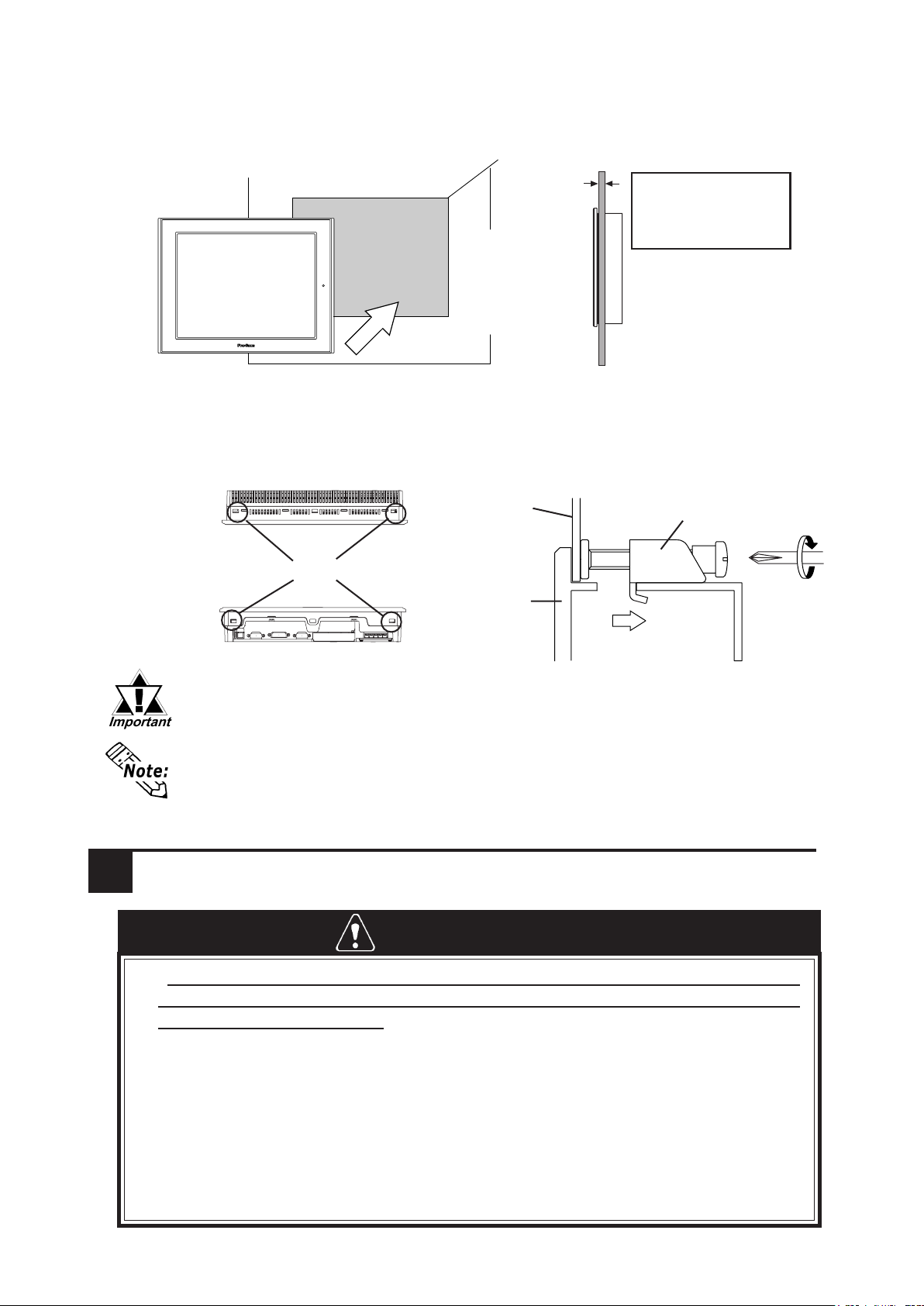
Attach the Installation Fasteners from Inside the Panel
The following figures show the four (4) fastener insertion slot locations. Insert each fastener's
hook into the slot. Tighten the screws in a diagonal pattern, and slowly increase the torque.
Create a Panel Cut and insert the FP into the panel from the front
6Wiring
Installation
fastener
FP
Panel
Unit: mm [in]
Panel
301.5 [11.87 ]
+1
0
+0.04
0
227.5
[8.96 ]
+1
0
FP
+0.04
0
Panel thickness
1.6mm[0.06in] to
10.0mm[0.39in]
•To avoid an electric shock, when connecting the FP unit's power cord terminals to
the power terminal block, confirm that the power supply is completely turned OFF,
via a breaker, or similar unit.
•FP2650-T41 unit is designed to use only AC100 to AC240V input. Any other power
level can damage both the FP and the power supply.
•Since there is no power switch on the FP unit, be sure to attach a breaker-type
switch to its power cord.
• When grounding the FP's FG terminal, comply with the instructions. If the FP's FG
terminal is grounded appropriately, there is the danger of an electrical shock (pro-
tective earth) or the danger of FP malfunction (functional earth).
WARNINGS
Panel
FP
Top
Bottom
Insertion Slots

Under 6.0mm(0.24in)
Over φ3.2mm(0.13in)
• Wherever possible, use thick wires (max.2mm2) for power terminals, and twist the
wire ends before attaching the ring terminals.
• Be sure to use the following size ring terminals.*1
• To avoid a short caused by loose ring terminals, be sure to use ring terminals with an
insulating sleeve.
*1 Suggested Ring Terminal : equivalent to V2-MS3 (made by JST)
• When the FG terminal is connected, be sure the wire is grounded. Not
grounding the FP unit will result in excess noise and vibration.
Connecting the AC Power Cord
When connecting the power cord, be sure to follow the procedures given below.
1. Confirm that the FP unit's Power Cord is unplugged from the power supply.
2. Use a screwdriver to remove the Power Input Terminal Block's clear plastic cover.
3. Unscrew the screws from the middle three (3) terminals, align the Ring Terminals
and reattach the screws.
4. Replace the Power Input Terminal Block's clear plastic cover.
• Confirm that the ring terminal wires are connected correctly.
• The torque required to tighten these screws is 0.5 to 0.6 N•m.
Rear of FP
Ring Terminals*1
Power Input Terminal Block
+ - FG
+ - FG
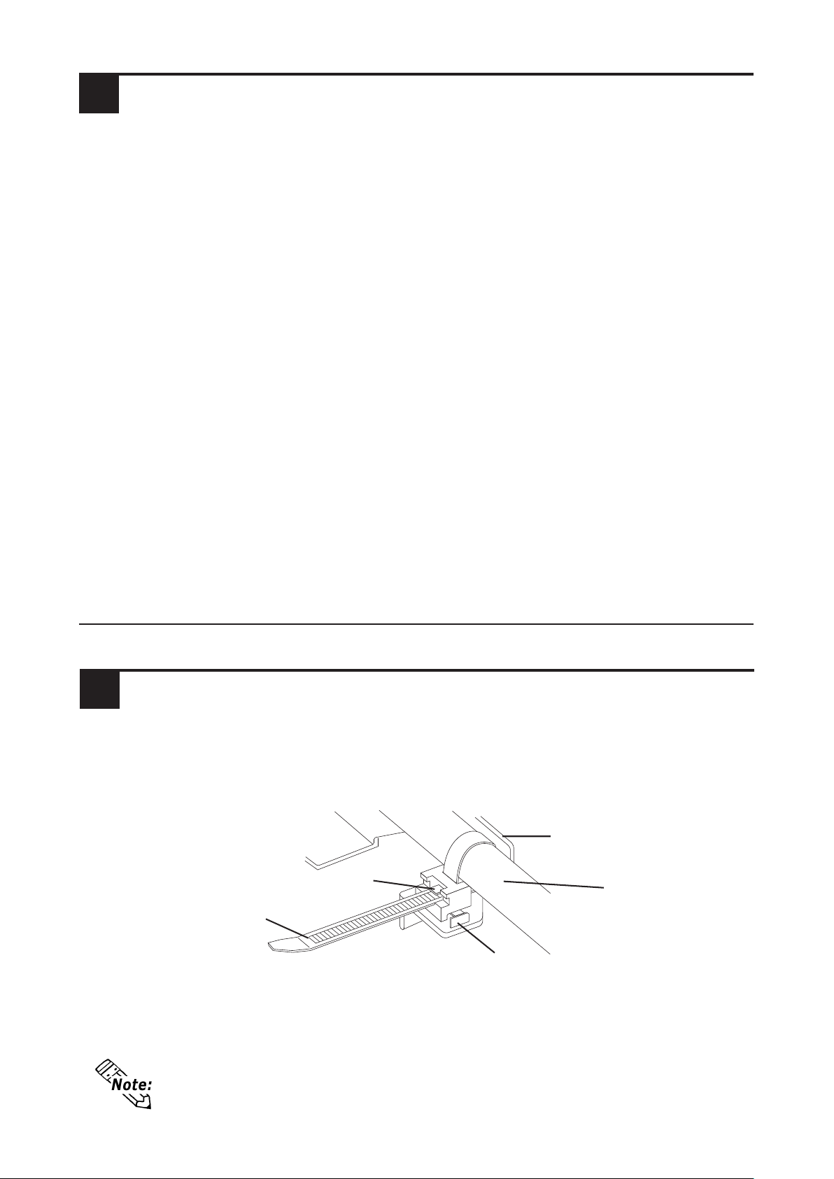
• If the stopper will not move, press on <A> (shown in figure) to free the
strap from the strap holder.
*1 Use a grounding resistance of 100
Ω
, a wire of 2mm2or thicker, or your country's
applicable standard.
7Power Supply Cautions
Power Supply Cautions
Please pay special attention to the following instructions when connecting the power
cord terminals to the FP unit.
•If the power supply voltage exceeds the FP unit's specified range, connect a
voltage transformer.
•Between the line and the ground, be sure to use a low noise power supply. If
there is still an excessive amount of noise, connect a noise reducing transformer.
•Input and Output signal lines must be separated from the power control cables
for operational circuits.
•The FP unit's power supply cord should not be bundled with or kept close to
main circuit lines (high voltage, high current), or input/output signal lines.
• When surge (indirect lightning stroke etc.) which corresponds to surge-resis-
tance specifications or more occurs, control surge by a surge absorber etc..
•To reduce noise, make the power cord as short as possible.
Grounding Cautions
•When attaching a wire to the FP unit's rear face FG terminal, (on the AC
Connector), be sure to create an exclusive ground.*1
Input / Output Signal Line Cautions
•All FP Input and Output signal lines must be separated from all operating circuit
(power) cables. If this is not possible, use a shielded cable and ground the shield.
Stopper
USB Cable Strap
USB Cable
USB Cable Strap Holder
<A>
USB Cable Strap Attachment Procedure
1) Insert the USB cable into the USB connector.
2) Tighten the strap until the cable is secured in place and insert the cable strap into the
cable strap holder as shown in the following figure.
USB Cable Strap Removal
1) Push in the cable strap's stopper with a standard flat-blade screwdriver until the cable
strap band unlocks, and remove the strap.
2) Disconnect the USB cable.
8Using the USB Cable Strap

Function
CONTRAST Adjusts the contrast. (Analog RGB only)*1
BLACK LEVEL Adjusts the color brightness. (Analog RGB only)*1
H-POS Adjusts the horizontal position of the screen.
V-POS Adjusts the vertical position of the screen.
H-SIZE Adjusts the screen size in the horizontal direction. (Analog RGB only)*1
PHASE Adjusts the input signal and the dot clock position. (32 levels)
(Analog RGB only)*1
BACKLIGHT Adjusts the backlight brightness. (9 levels)
AUTO GAIN CONTROL Automatically adjusts the contrast and the brightness.
(Analog RGB only)*1
DISPLAY MODE Displays the resolution of the input image data.
OSD CLEAR (RESET ) Resets the current OSD value to the default value.
OSD SAVE Save the current value and quit the OSD.
SYSTEM Changes settings such as activating the click sound.
ESCAPE Cancels the setting and returns to the upper level. In the main menu,
this command closes the OSD.
Item
*1 When using DVI-D, the message "DO NOT NEED SETUP FOR DVI-D" is displayed and
no settings are required.
OSD Features
Use the FP unit's touch panel and the OSD (On Screen Display) menu to set the FP
screen settings, and fine-tune your screen's display. You can enter these settings even
while the FP si operating.
The following table explains each OSD setting item and its function.
Starting the OSD
To start the OSD and enter OSD mode, touch the touch panel's corners in the following
order : (1) upper left (2) upper right (3) lower right, all within 5 seconds. In OSD mode, the
setting screen will appear in the center of the screen. Until OSD setup is completed the
touch panel cannot be used to export data to external devices.
Main Menu
" " : OSD version.
9Screen Display Adjustment

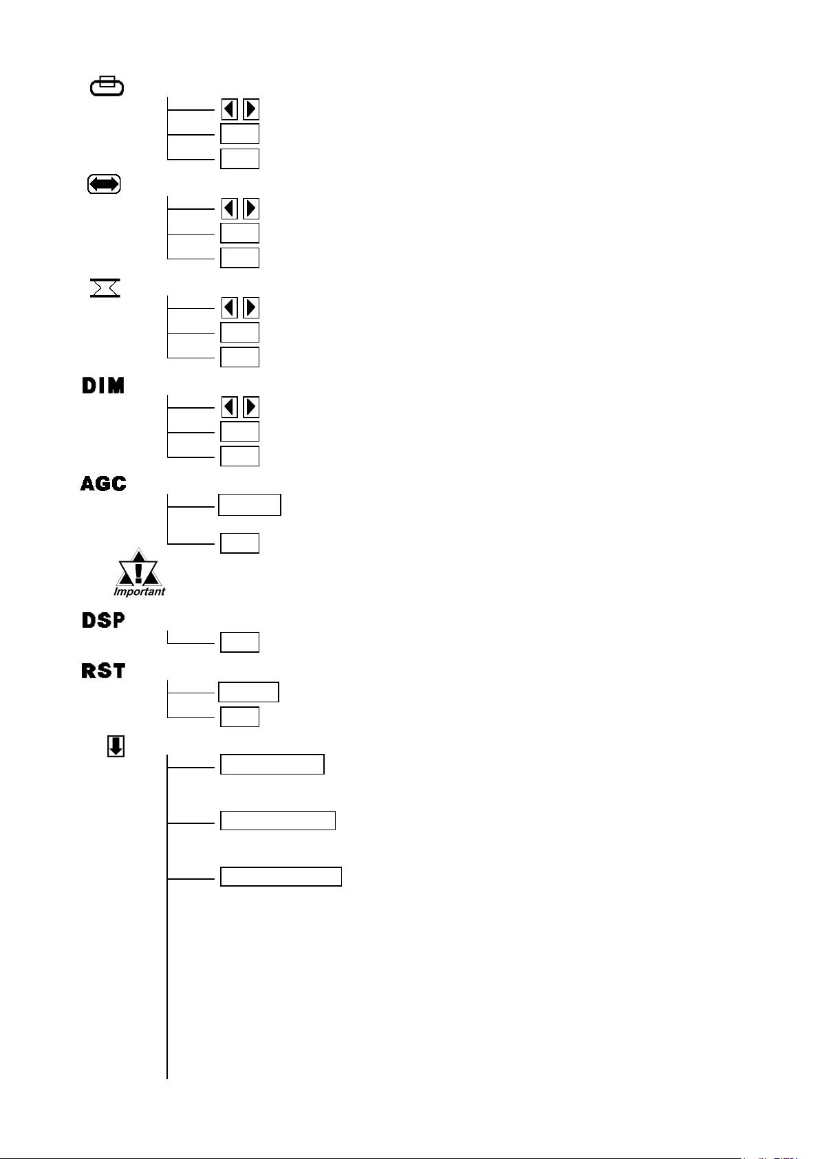
Icons on the screen are used to operate the OSD. When you start up the OSD, the main
menu appears. Touching the icon of the item you want to adjust displays its submenu or
setting change screen. In the setting change screen, and icons are used to change the
setting. To apply the setting, press the SET button. Press the SAVE button to save the
defined settings.
Using the OSD
To quit the OSD, press the ESC button in the main menu or level the OSD as it is for at
least 30 seconds. If the OSD is automatically closed after 30 seconds of inactivity, the
values set before the OSD was closed will be applied.
Quitting the OSD
OSD Menu and Operation Tree
ESC Cancels the setting and then returns to the main menu.
Adjustment buttons
SET Applies the setting and then returns to the main menu.
BLACKLEVEL
ESC Cancels the setting and then returns to the main menu.
H-POS
SET Applies the setting and then returns to the main menu.
Adjustment buttons
ESC Cancels the setting and then returns to the sub contrast
adjustment screen.
ESC Returns to the contrast menu.
BB contrast
Adjustment buttons
SET Applies the setting and then returns to the sub contrast
adjustment screen.
SET Applies the setting and then returns to the sub contrast
adjustment screen.
ESC Cancels the setting and then returns to the sub contrast
adjustment screen.
ESC Cancels the setting and then returns to the sub contrast
adjustment screen.
GG contrast
Adjustment buttons
RR contrast
Adjustment buttons
SET Applies the setting and then returns to the sub contrast
adjustment screen.
CONTRAST
ESC Cancels the setting and then returns to the main menu.
Sets the contrast setting and then moves to the sub contrast menu.
SET Applies the setting and then returns to the main menu.
Adjustment buttons
• The OSD is not displayed when SW1-2 is set to ON.
V-POS
Adjustment buttons
SET Applies the setting and then returns to the main menu.
ESC Cancels the setting and then returns to the main menu.
H-SIZE
Adjustment buttons
SET Applies the setting and then returns to the main menu.
ESC Cancels the setting and then returns to the main menu.
PHASE
Adjustment buttons
SET Applies the setting and then returns to the main menu.
ESC Cancels the setting and then returns to the main menu.
BACKLIGHT
Adjustment buttons
AUTO GAIN CONTROL
SET Applies the setting and then returns to the main menu.
ESC Cancels the setting and then returns to the main menu.
START Starts the auto gain control and then automatically returns to the main
menu.
ESC Returns to the main menu.
DISPLAY MODE
ESC Returns to the main menu.
OSD CLEAR
START Clears the setting.
ESC Cancels the setting and then returns to the main menu.
SYSTEM
CLICK TONE Enables/disables the click sound. With this parameter, the
sound level can also be adjusted.
(Default value : OFF <Click sound disabled>)
Select the time period from 1min, 3min, 5min, 10min, and OFF
(Auto OFF function disabled).
720×400 DSP When an input data resolution of 720 X 400 is used in the VGA
text mode, set this parameter to ON. For other resolutions, set
this parameter to OFF. (Default : OFF)
AUTO OFF DSP Enables/disables the screen display Auto OFF function and
sets the time when the Auto OFF function is enabled.
(Default : OFF <Auto OFF function disabled>)
The Auto OFF function automatically turns off the display to
prevent the screen from burning out when the touch panel is
not used for some period of time. With this parameter, you can
set the time interval to turn off the screen display (how much
time passes before the screen display is turned off) when the
touch panel is not used. If the touch panel is not touched over
the set time, the backlight will automatically turns off.
• Be sure to perform the auto gain control when the screen has both 100%
black and 100% white areas displayed.

BL ALARM Enables/disables the Backlight burnout detect function.
(Default : ON)
When a burned-out backlight is detected, the status LED
flashes alternately green and red, or a steady orange.
Touch-operation will be disabled when the backlight burns out,
which prevents the FP from sending input signals to the PLC.
SET Applies the setting and returns to the main menu.
The H-POS might exceed its adjustable range when
analog RGB interface is applied. In that case, this function can
be effective for adjusting the out-of-range H-POS so that you
change the Polarity Lock from OFF to ON.
(Default: OFF <Polarity Lock function disabled>)
ESC Cancels the setting and returns to the main menu.
SAVE Saves all the adjusted settings in the EEPROM.
POLARITY LOCK
•In the OSD, pressing the SET button applies the set value and enables the
setting. The set value won't be canceled unless the power is turned OFF or
the value is reset.
If the power is turned OFF without saving the set value, that data will
disappear. The last saved data will be read into the system when the FP
starts. To enable the changed value, be sure to press the SAVE button.
•When the OSD automatically closes after 30 seconds of inactivity, the set
value that you were modifying at the time will be retained. If you quit the
OSD with the ESC button, the value that you were modifying will be not be
retained and the previously set value will be used.
• In the system setting screen, touching the value displayed on the panel changes
the value of the time period.
• Normally, the FP unit detects a backlight burnout by
monitoring the backlight's current flow, however, the
FP may fail to detect this condition, depending on the
type of backlight problem.
• The setting functions after the OSD closes.

10 Replacing the Backlight
The FP unit's backlight is user replacable.
For an explanation of how to replace the FP unit's backlight, please refer to the
FP2650-T41 User Manual or the backlight's Installation Guide.
Corresponding Replacement Backlight Model Numbers
Use of a different model backlight may cause a FP malfunction or breakdown.
FP Model No. Backlight Model No.
FP2650-T41 CA5-BLU12XGA-01
Digital Electronics Corporation
8-2-52 Nanko Higashi, Suminoe-ku, Osaka 559-0031, Japan
URL: http://www.pro-face.com/
Please be aware that Digital Electronics Corporation shall not be held liable by the user for any
damages, losses, or third party claims arising from the uses of this product.
060124A .FP2650-T41-ENG 2005.2 JM/A © 2005 Digital Electronics Corp.
Notice
Table of contents
Other Pro-face Monitor manuals

Pro-face
Pro-face Xycom SXT1811 Installation instructions

Pro-face
Pro-face GP-3750T User manual

Pro-face
Pro-face GP77R Series Instruction manual

Pro-face
Pro-face PL-X900 Series User manual

Pro-face
Pro-face FP3900-T41 User manual

Pro-face
Pro-face GP-3300T Manual

Pro-face
Pro-face FP3650-T41 User manual

Pro-face
Pro-face GC4000 Series User manual

Pro-face
Pro-face SP5000 Series User manual

Pro-face
Pro-face GP-4201TM User manual


