ProJet MJP 2500 User manual
Facility Requirements Guide
ProJet MJP2500,MJP 2500 Plus &
MJP 2500W
Facility RequirementsGuide
p/n 33-D131Rev C
Original Instructions
Please refer back tohttp://infocenter.3dsystems.com/projetmjp2500/facility-requirements-guidefor the most up-to-date facility
requirements guide
About This Manual
This document includes the overall facility requirements that will be needed to have a successful installation when our authorized 3D Systems
representatives arrive to install your 3D printer system.
®

What is a Facility Requirements Guide
This guide provides important information on selecting a facility location and planning for the installation of 3D Systems’ ProJet® MJP 2500
Professional Printing System. It also presents planning guidelines to facilitate fast, convenient installation and operation of your 3D printer system.
What’s Inside:
Descriptions of hardware, software, part material, networking components, and documentation that comprise the ProJet® MJP 2500
Professional Printing System.
An overview of the site requirements in typical engineering and design work spaces. These involve basic access, electrical, and environmental
conditions for conguring a safe and ecient work area.
A checklist is included to ensure that the facility is adequately prepared for installation of your 3D printer system.
Information on how to obtain assistance from 3D Systems Customer Support Team.
Common Symbols Used Throughout 3D Systems Manuals
The ProJet® MJP 2500 Professional Printing System is part of 3D Systems’ Multi-Jet-Printing (MJP) product line.
UV RADIATION HAZARD: Invisible UV radiation is accessible in the vicinity of this sign or behind the panel. Radiation can cause eye injury
or blindness, burn injury and/or re. Access panels are for service only and should be opened only by certied service personnel (ProJet
2500/2500 Plus only)
ELECTRICAL SHOCK HAZARD: High voltage electricity is accessible in the vicinity of this sign or behind the access panel. High voltage can
cause severe burns or death, as well as res. Access panels are for service only and should be opened only by certied service personnel
or trained maintenance personnel.
HOT SURFACE HAZARD: A hot surface is accessible in the vicinity of this sign or behind the access panel. Avoid contact. Hot surfaces can
cause burn injury or re. Allow surface to cool before touching. Access panels are for service only and should be opened only by certied
service personnel or trained maintenance personnel.
THIS GLOBAL HARMONIZED SYSTEM LABEL FOR LOW LEVEL TOXICITY. THIS INCLUDES RESPIRATORY, SKIN, AND EYE IRRITATION, SKIN
SENSITISERS AND CHEMICALS HARMFUL IF SWALLOWED, INHALED OR IN CONTACT WITH SKIN.
CAUTION: Indicates the possibility of loss of data or damage to equipment.
WARNING: INDICATES THE POSSIBILITY OF INJURY OR DEATH TO PERSONNEL.
HAND ENTANGLEMENT WARNING:GEARS OR MOVING PARTS HAZARD IN THE VICINITY OF THIS SIGN OR BEHIND THE ACCESS PANEL.
ACCESS PANELS ARE FOR SERVICE ONLY AND SHOULD BE OPENED ONLY BYAUTHORIZED SERVICEPERSONNEL.
WEAR GLOVES: Wear the appropriate gloves when required. For example, when touching surfaces that may contain or have been exposed
to materials, wear nitrile gloves. Heat gloves are necessary when touching surfaces that may be hot to ensure burns don’t occur.
ULTRAVIOLET RADIATION INSIDE: Exposure may cause eye damage. Do not operate without covers. Wear UV eye protection.
NOTE: A note signies important information but not information of a critical content.

The ProJet Professional Printing System
Your ProJet®MJP 2500 Series Printerships with the following:
One crated ProJet®MJP 2500 Professional Printing System containing the following accessories and materials.
Two Build Platforms (one on the printer and one in an accessory box)
Region-specic “country kit” consisting of one power cable
Two full cartridges ofVisiJetPart Material and two full cartridge ofSupport Material
One pack of nitrile gloves
10 Waste Bags
2 cartridge holders
SIM card (ProJet®MJP 2500 Plus only)

Preparation for Shipment Arrival
The following topics should be arranged PRIOR TO THE ARRIVAL OF THE SYSTEM, to simplify installation of the ProJet® MJP 2500 Professional
Printing Systems.
Make sure the following resources are available:
____ A forklift or similar, heavy-duty equipment required for unloading the 3D printer system crate from the truck to thede-crating location. (Forklift is
not required to move 3D printer system into where it will be installed once thecrate is removed.)
____ Network connection(s)
____ Power outlet(s) - a dedicated circuit to power the 3D printer system
____ Storage cabinetry for extra 3D printer system material containers and other consumables
____ At least one (1), networked graphics workstation or CAD/CAM/CAE terminal meeting the requirements described inClient Workstation
Requirements.
NOTE: Retain the shipping crate, ramps, brackets and hardware in the event the ProJet® MJP 2500 Professional Printing System needs to be
shipped in the future. These crates are designed to allow fast, easy removal and packaging of the product. If 3D printer system needs to be
shipped, contact 3D Systems Customer Support for shipping instructions.

Facility Guidelines
This section provides details relating to site selection, site preparation and readiness of the facility to accept and install the ProJet® 2500
Professional Printing System. Discuss the appropriate equipment locations with a 3D Systems' Certied Partner, so that the equipment is located in
a convenient, appropriate location based on your organization's needs. When planning an installation, consider.
Electrical Requirements Network Interface
Space Planning Post Processing Accessories (Oven and Freezer)
Access Area Surrounding 3D Printer System Material Storage
Unit Portability Material Bottle Disposal
Client Workstation Requirements PrinterWeights and Printer Dimensions
Electrical Requirements for the ProJet® MJP 2500 Series Printer:
Space Planning The outlet location must be near the 3D printer system and
remain accessible to the end user at all times.
An additional 100 or 220 VAC outlet is recommended for service
needs.
A phone near the 3D printer system is recommended to
facilitate 3D printer system support.
Each location of the 3D printer system requires a standard wall power
outlet or power drop to power the 3D printer system.
AC Voltage and Current Requirements:
Each 3D printer system requires use of a dedicated circuit that will allow for100-127 VAC, 50/60 Hz, 15A, single phase or200-240 VAC, 50 Hz,
10A, single phase Single C14 receptacle.
All ProJet® MJP 2500 series printers relies on a connection to the mains protective earth (ground). Thisprovides aone level of protection to the
user (Basic Insulation).
The installation of The ProJet® MJP 2500 Professional Printing System shall comply with the National Standards of the country in which it is
placed.
Protected Power/Un-interruptible Power
Many customers face AC power quality issues requiring the use of a UPS (Uninterruptible Power Supply) and generator to correct. The primary
function of a UPS is to hold up AC power for a limited period of time by using energy from rechargeable batteries. For brief power outages, a UPS is
sucient; the amount of holdup time may also be scaled with additional battery packs according to customer needs. For extended power outages,
some combination of UPS and on-site generator is required. The secondary benets of a UPS often include line conditioning (correcting for voltage
sags and swells) and line surge protection. A double-conversion, true sine-wave UPS is recommended as it provides additional immunity from
powerline perturbations.
3D Systems has tested the product with the following UPS models:
North America
Manufacturer Model Voltage
In
Voltage
Out
kW Input
Connector
Output
Connector(s)
APC SURTA3000XL 120 120 2.1 L5-30P 5-20R

North America
Eaton 9PX3000RT 120 120 2.7 L5-30P 5-20R, L5-30R
Liebert GXT4-3000RT120 120 120 2.7 L5-30P 5-20R, L5-30R
Worldwide
Manufacturer Model Voltage
In
Voltage
Out
kW Input
Connector
OutputConnector(s)
APC SRT3000XLW-IEC 208/230 230 2.7 C20 IEC C13, IEC C19
Eaton 9PX3000GRT 208/230 230 3.0 C20 IEC C13, IEC C19
Any UPS unit will impose additional facilities considerations including battery storage, oor space, interconnect and electrical receptacle
requirements. For example, the above North-America UPS models require an L5-30 receptacle.
If additional or substitute cordsets are required, the cordset shall be rated greater than or equal to the input current rating of the product at the
voltage applied. For example, a C13 to C14 cordset will be required if the UPS provides C13 receptacles (typical in markets outside North America).
Recognizing that customer needs and facilities differ greatly, 3D Systems encourages customers to contact one of the above UPS manufacturers for
a power protection solution tailored to the customer and site needs.
ProJet® XL Finisher (Optional) Power Requirements
The ProJet® XL Finisher must be hardwired andinstalled by a Certied Electrician. For more information about the ProJet® XL Finisher clickhere.
Client Workstation Requirements
Before a print can be printed on the printer, the print data le must be saved or exported to the industry-standard .stl le format, and submitted over
the network. 3DSPRINT client software is located on 3DS Central can be installed on each intended users’ workstation to allow them to select,
preview, and submit jobs; as well as manage the print queue.For more information onsending aleto the 3D printer system see the ProJet® MJP
2500 User’s Guide available on:
http://infocenter.3dsystems.com/projetmjp2500/user-guide(Acrylate)
http://infocenter.3dsystems.com/projetmjp2500w/user-guide(Wax)
Prior to installing the software, ensure that the initially selected workstation meets the following minimum specications. Although the ProJet®
2500 client software will run on less powerful computers, meeting the minimum recommended conguration will ensure acceptable performance. It
is recommended that this workstation be further enhanced with the recommended requirements for maximum performance, particularly with more
powerful processors and added memory.
System Requirements
OS Minimum
- Windows 7 (64-bit)
-Windows 8 (64-bit)
-Windows 10 (64-bit)
Recommended
CPU - Intel or AMD processor with
a minimum of 2.0GHz
- Multiple core processor
- Hyper threading and clock speeds above 3GHz
can be benecial but should be paired with a good
balance of cores.

RAM -4 GB - 8GB or more
- Virtual Memory: In Win 7, Win 8, Win 10, it is
recommended to use the defaultoption;
"Automatically manage paging le size for all
drives"
Hard Disk -30 GB of available hard-disk
space for cache
-Temporary le cache requires
about 3GB free disk space for
optimal print le transfers
-SSD or 10,000RPM HDD
Display/GPU -Open GL 2.1 and GLSL 1.20
enabled graphics card
-Screen resolution 1280x960
-NVidia or AMD GPU with 1GB of RAM or more
-Screen resolution 1280x1024 or higher
Other -Internet Explorer 9 or newer
-Microsoft .NET Framework 4.5
(installed with application)
-3 button mouse with scroll
-Keyboard
-Google Chrome or Internet Explorer 11
I/O -Either ethernet or wireless
connection
-Ethernet may be more stable depending on the
facility
Network Interface
The ProJet® 2500 Professional Printing System requires an Ethernet network connection to transfer print jobs from workstation(s) to the printer.
An established TCP/IP network is setup and enabled. An RJ45 Ethernet network connection for each printer to be installed at the delivery site must
be installed, tested and functioning. The printer can use either DHCP or a static assigned IP address. A DHCP server automatically programs an IP
address; otherwise, a network administrator can manually assign a permanent IP address for each printer that is to be connected to the network.
Write IP address(es) here:
___________________________________________________________________
Space Planning
Included in this guide is information and dimensions required to help plan installation of the printer.
Crated Clearance
The 3D printer system is intended to be lifted from the shipping truck using a forklift. Have a forklift available for the 3D Systems Customer Support
Engineer (CSE) or reseller when installation occurs. The crate can then be removed, and the ramps placed as shown below. Store crate pieces where
it will be easy to access should the printer need to be sent back or shipped to another location. Based on the crate size, you must have at least
192”(488mm) (approx. 16’) to accommodate the pallet, ramps and printer, the required footprint to uncrate is approximately 7’ x 16’.(2.13x4.88m)
CAUTION: NEVER unpack, assemble, or connect any component of the shipment without the aid of a qualied, 3D Systems Customer Support
Engineer or certied partner. 3D Systems accepts no responsibility for damaged, defective, or incomplete systems uncrated by anyone other
than 3D Systems Customer Support Engineer or certied partner.
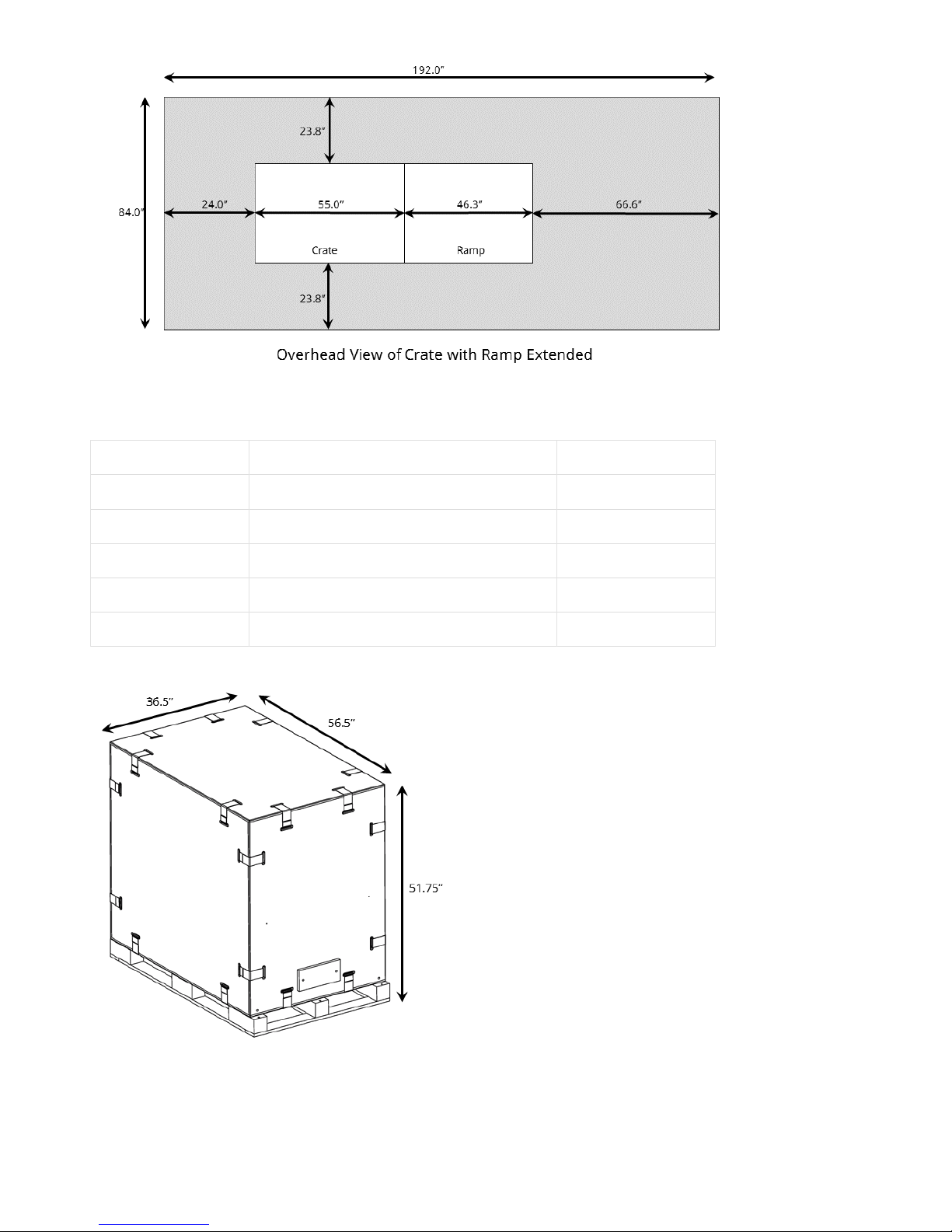
Requirement Metric English
Crated size 1435mmx 927.1mm x 1314.5mm(L x W x H) 56.5” x 36.5” x 51.75”
Crated weight 324kg 715 lbs.
Uncrated size 1117.6mm x 741.7mm x 1061.7mm (L x W x H) 44” x 29” x 41.8”
Uncrated weight 211kg 465lbs.
Floor Flatness / Level 2.5cm over 12m 1” over 3’
Crate Dimensions and Weight
Unit Portability
The ProJet® 2500 Printing System is equipped with four caster-type rollers and four leveling feet. Leveling can be adjusted by locking the casters in
place while adjusting leveling feet as required until 3D printer system is level.
Access Area Surrounding Uncrated 3D Printer System
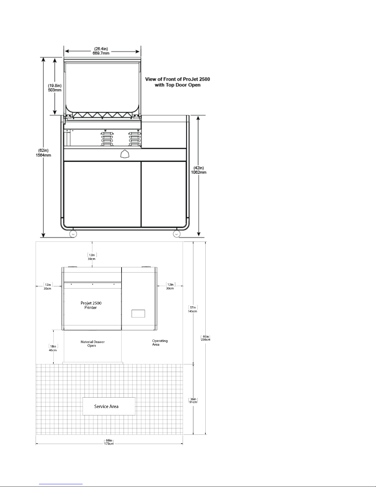
At least 12" (30cm) of unobstructed oor space is recommended behind and on either side of the printer for airow with 18" (46cm) in front of the
printer to be able to open the material drawer. It is recommended that 36" (91cm) either behind or in front of the printer for service access. Behind
would allow service to obtain access from the back, if the space is left in front, the printer will need to be moved out away from wall using that space
in front to do so.
Freezer
Other manuals for MJP 2500
1
This manual suits for next models
2
Table of contents
Other ProJet 3D Printer manuals

ProJet
ProJet MJP 2500 User manual

ProJet
ProJet MJP 5600 User manual

ProJet
ProJet MJP 5600 User manual

ProJet
ProJet 3-D Modelers User manual

ProJet
ProJet MJP 5600 User manual

ProJet
ProJet 5500X User manual

ProJet
ProJet HD3000 User manual

ProJet
ProJet MJP 2500W User manual

ProJet
ProJet 1000 User manual

ProJet
ProJet PJ 5000 User manual


