Promac SX-823DGSVI User manual

01-2018
Schweiz / Suisse
JPW (TOOL) AG
Tämperlistrasse 5
CH-8117 Fällanden Switzerland
www.promac.ch
France
TOOL France / PROMAC
57, rue du Bois Chaland, Z.I. du Bois Chaland
case postale 2935 FR-91029 Evry Cedex
www.promac.fr
SX-823DGSVI
SX-827DGSVI
Metal Band Saw
Metallbandsäge
Scie à ruban

CE-Conformity Declaration
CE-Konformitätserklärung
Déclaration de Conformité CE
Product / Produkt / Produit:
Metal Band Saw
Metallbandsäge
Scie à ruban
SX-823DGSVI / SX-827DGSVI
Brand / Marke / Marque:
PROMAC
We hereby declare that this product complies with the regulations
Wir erklären hiermit, dass dieses Produkt der folgenden Richtlinie entspricht
Par la présente, nous déclarons que ce produit correspond aux directives suivantes
2006/42/EC
Machinery Directive
Maschinenrichtlinie
Directive Machines
2014/30/EU
electromagnetic compatibility
elektromagnetische Verträglichkeit
compatibilité électromagnétique
designed in consideration of the standards
und entspechend folgender zusätzlicher Normen entwickelt wurde
et été développé dans le respect des normes complémentaires suivantes
EN ISO 12100:2010
EN 13898:2003+A1:2009
EN 60204-1:2006+A1:2009
EN 61000-6-2:2005
EN 61000-6-4:2007+A1:2011
Manufacturer / Hersteller / Fabricant:
JPW (Tool) AG, Tämperlistrasse 5,CH-8117 Fällanden
Schweiz / Suisse / Switzerland
Responsible for the Documentation / Dokumentations-Verantwort ung/ Résponsabilité de Documentation:
Hansjörg Meier
Head Product-Mgmt. / Leiter Produkt-Mgmt. / Resp. Gestion des Produits
GA)looT(WPJ
JPW (Tool) AG, Tämperlistrasse 5, CH-8117 Fällanden
Schweiz / Suisse / Switzerland
2017-12-10 Jan Dätwyler, General Manager

Contents
Chapter 1 Chapter 6
ACCIDENT PREVENTION AND SAFETY
REGULATION ROUTINE AND SPECIAL MAINTENANCE
6.1 Daily maintenance..............................................9
1.1 Advice for the operator.....................................2 6.2 Weekly maintenance..........................................9
1.2 The electrical equipment according to European
Standard" CENELEC EN 60204-1" ........................2 6.3 Monthly maintenance .........................................9
6.4 Six-monthly maintenance...................................9
1.3 Emergencies according to European Standard
“CENELEC EN 60204-1”........................................2 6.5 Maintenance of other machine parts..................9
6.6 Oils for lubricating coolant..................................9
Chapter 2 6.7 Oil disposal.........................................................9
6.9 The gear box ......................................................9
MACHINE DIMENSIONS TRANSPORT
INSTALLATION DISMANTLING 6.10 Special maintenance.......................................9
Chapter 7
2.1 Machine dimensions.........................................2
2.2 Assembling the control box to the saw.............2 TECHNICAL CHARACTERISTICS
2.3 Machine Transportation....................................3 7.1 Table of cutting capacity and technical details.10
Chapter 8
2.4 Minimum requirements for housing the machine
................................................................................3
MATERIAL CLASSIFICATION AND CHOICE OF
TOOL
2.5 Anchoring the machine.....................................3
2.6 Instructions for assembly of the loose parts and
accessories.............................................................3 8.1 Definition of materials.......................................10
8.2 Selecting blade.................................................10
2.7 Deactivation of machine...................................3 8.3 Teeth pitch........................................................11
2.8 Dismantling.......................................................3 8.4 Cutting and advance speed..............................11
Chapter 3 8.5 Blade running-in...............................................11
8.6 Blade structure.................................................11
THE MACHINE’S FUNCTIONAL PARTS
8.7 Blade type.........................................................11
3.1 The saw arm.....................................................3
Chapter 9
3.2 Control panel....................................................4
3.3 Vise adjustment................................................4 NOISE TESTS........................................................12
3.4 Cutting angle adjustment..................................5 Chapter 10
3.5 The base...........................................................5
WIRING DIAGRAM................................................13
3.6 The operation cycle ..........................................5
Chapter 11
Chapter 4
TROUBLESHOOTING
ADVICE ON USING YOUR BANDSAW
11.1 - Blade and cut diagnosis...............................15
4.1 Recommendations and advice for using the
machine..................................................................6 Chapter 12
Chapter 5 MACHINE COMPONETS
12.1 Parts list..........................................................19
ADJUSTING YOUR MACHINE
12.2 Explosion drawings.........................................22
5.1 Blade tension assembly....................................7
5.2 Adjusting the blade guide.................................7
5.3 Saw frame return stroke-limiting device...........8
5.4 Changing the blade...........................................8
5.5 Adjusting the blade to the flywheels.................8
5.6 Replacing saw frame return spring...................9
-1
-
6.8 Coolant system...................................................9

1ACCIDENT PREVENTION AND
SAFETY REGULATION 1.3 Emergencies according to European
Standard “CENELEC EN 60204-1”
- In the event of incorrect operation or of danger
conditions, the machine may be stopped
immediately by pressing the red mushroom
button.
This machine has been designed to comply with
national and community accident-prevention
regulations. Improper use and/or tampering with the
safety devices will relieve the manufacturer of all
responsibility. - The casual or voluntary removal of the blade
cover of the flywheels causes the stepping-in of a
interlock switch that automatically stops all
machine functions.
1.1 Advice for the operator
- Check that the voltage indicated on machine
motor is the same as the line voltage. - In case blade breakage, the tension release micro
switch disconnects all machine functions.
- Check the efficiency of your electric supply and
grounding system; connect the power cable of the
machine to the socket and the ground lead
(yellow-green in color) to the grounding system.
NOTE: Resetting of machine operation after each
emergency stop requires specific restart button.
- When the saw frame is in suspended mode (or
raised) the blade must not move. 2MACHINE DIMENSIONS
TRANSPORT INSTALLATION
DISMANTLING
- Only the blade section used for cutting must be
kept unprotected. To remove guards operate on
the adjustable head.
- It is forbidden to use the machine without its
shields 2.1 Machine dimensions
- Always disconnect the machine from the power
socket before blade change or carrying out any
maintenance job, even in the case of abnormal
machine operation.
- Always wear suitable eye protection.
- Never put your hands or arms into the cutting area
while the machine is operating.
- Do not shift the machine while it is cutting.
- Do not wear loose clothing like: shirts with sleeves
that are too long, gloves that are too big, bracelets,
chains or any other object that could get caught in
the machine during operation. Tie back long hair.
- Keep the area free of equipment, tools, or any
other object.
- Perform only one operation at a time. Never
have several objects in your hands at the same
time. Keep your hands as clean as possible.
- All internal operations, maintenance or repairs,
must be performed in a well-lit area or where there
is sufficient light from extra sources so as to avoid
the risk of even slight accidents
1.2 The electrical equipment according to
European Standard" CENELEC EN 60204-1"
- The electrical equipment ensures protection
against electric shock as a result of direct or
indirect contact. The active parts of this
equipment are housed in a box to which access is
limited by screws that can only be removed with a
special tool; the parts are fed with alternating
current as low voltage (24V). The equipment is
protected against splashes of water and dust.
2.2 Assembling the control box to the saw
- Protection of the system against short circuits is
ensured by means of rapid fuses and grounding;
in the event of a motor overload, protection is
provided by a thermal probe.
- In the event of a power cut, the specific start-up
button must be reset.
- The machine has been tested in conformity with
point 20 of EN 60204
- Attach the control box to the saw with two
provided set screws.
-2
-
SX-827DGSVISX-823DGSVI

4) Empty the coolant tank
2.3 Machine Transportation 5) Carefully clean and grease the machineTo move the machine,
use a forklift truck or sling it with straps as
illustrated. 6) If necessary, cover the machine.
2.8 Dismantling (due to deterioration and/or
obsolescence)
General rules
If the machine is to be permanently demolished
and/or scrapped, divide the material to be disposed
of according to type and composition, as follows:
1) Cast iron or ferrous materials,composed of
metal alone, are secondary raw materials, so they
may be taken to an iron foundry for re-smelting after
having removed the contents (classified in point 3).
2) Electrical components, including the cable and
electronic material (magnetic cards, etc.), fall within
the category of material classified as being
assimilated to urban waste according to the laws of
your local, state, or federal government, so they
may be set aside for collection by the public waste
disposal service;
2.4 Minimum requirements for housing the
machine 3) Old mineral and synthetic and/or mixed oils,
emulsified oils and greases are considered
hazardous or special refuse, so they must be
collected, transported and disposed of at a special
waste disposal service.
- Main voltage and frequency must comply with the
machine’s motor requirements.
- Environment temperature should fall within –10 ºC
to +50ºC. NOTE: The standards and legislation concerning
refuse is in a constant state of evolution, therefore
is subject to changes. The user must keep
informed of the regulations at the time of disposal
as these may differ from those described above.
- Relative humidity cannot be over 90%.
2.5 Anchoring the machine
3THE MACHINE’S FUNCTIONAL
PARTS
3.1 The saw arm
Machine parts consisting of drive members (gear
motor or variable speed motor, flywheels), tension
and guides (blade guide slide, blade guide blocks)
of blade.
Position the machine on a firm cement floor,
maintaining, at therear, a minimum distance of 800
mm from the wall; anchor it to the ground as shown
in the diagram, using screws and expansion plugs
or tierods sunk In cement, ensuring that it is sitting
level.
2.6 Instructions for assembly of the loose parts
and accessories
Fit the components supplied:
Detail 1 Mount bar-stop rod
Detail 2 Mount and align the roll-supporting arm as
per the counter-vise table.
2.7 Deactivation of machine
- If the sawing machine is to be out of use for a long
period, it is advisable to proceed as follows:
1) Detach the plug from the electric supply panel
2) Loosen blade
3) Release the saw arm return spring
-3
-

3.2 Control Panel 1~17 Indicator lights
Red- Warning indicator
Yellow- Selection indicator
Green- Operation indicator
2 3 4 5
A1. Power supply ON, indicator lights
12. Saw bow up, indicator light
C D E3. Saw bow down, indicator light
4. Hand operation, indicator light
B5. Foot pedal operation, indicator light
6. Cycle start switch indicator light
767. Start switch (hydraulic flow control), indicator
light
8. Saw bow maximum height, indicator light
G F 9. Saw bow lowest height, indicator light
10. Open blade cover, warning indicator light
11. Improper speed selection, warning indicator
light
A~K Control Switches
A. Blade speed display
A1
Blade speed adjusting kno
B. Main connect switch
C. Saw bow up switch
D. Saw bow down switch
E. Hand/foot pedal operation selector
F. Cycle start switch
G. Hydraulic Start switch
H. Emergency button
I. Footpad emergency button
J. Footpad switch
K.
Bow down flow regulator
12. Motor overload, warning indicator light
13. Broken blade, warning indicator light
14. Emergency button indicator light
15. Hydraulic motor overload, warning indicator
light
16. Foot pad’s emergency button indicator light
17. Foot pad, operation indicator light
3.3 Vise adjustment
Clamping the Work Piece
- Place work piece between the jaws.
- Use the hand wheel to close the vise jaw. For
multiple cuts of a same size material, leave a small
gap between the work piece and vise jaw. Push
cycle start button (F). The vise will automatically
clamp the work piece while going through the
operation cycle. When the operation cycle is
finished, the vise will open and the work piece can
be adjusted or replaced.
Operation of the Vise
11
13
10
12
16 8
17
14 9
15
I
A1
HK
J
-4
-
1
b

When cutting angles, it may require the adjustment
of the vise jaw’s position so that the saw blade’s
path is not impeded. Follow the procedures below.
- Release the track support by turning handle (1)
counter-clockwise.
- Release the vise by moving the lever (2) to the
left.
- The vise may now be moved to right position or
left position by pushing with one hand on the
adjustable vise jaw and the other hand on the
track handle (1).
- Once in position, move the lever (2) to the right to
lock it into position. If the lever (2) is not between
the vise/bed mounts and facing the user, then the
vise will not be able to lock. If the vise lever (2)
has gone beyond or is obstructed by a vise/bed
mount, then use the following procedures.
J
- Adjust the lever (2) by grasping at the pivot point
(P) and lowering it, which may assist in the
adjustment. The lever can now be freely rotated
into a more convenient position. Some
movement of the vise jaw may be required. Raise
the lever (2) then move to the right to lock.
- Lock the track support (1) by turning handle
clockwise. The main connect switch is designed with a lock
hole. A lock can be attached to the lock hole to
prevent machine operation for safety and security
purposes.
-To use the footpad switch (J), first use the side of
the foot to push aside the plastic clip that blocks
the foot pad. Be careful not to damage the clip by
using excessive force or stomping on the footpad.
Next, step down on the footpad to start operation.
3.6 The operation cycle
- Make sure the voltage indicated on machine motor
is the same as power source voltage. Connect
the machine to the power source, and Press the
main connect switch (B). If power indicator light
(1) is on, it means the voltages are okay.
3.4 Cutting angle adjustment
*Note: While selecting the cutting speed indicator
light will blink.
Cutting at angles
-Angle can be cut up to 60
-Unlock lever (L) by pushing it to the left side.
-Rotate the saw arm to the desired angle by
following the index on the scale.
-Lock lever (L) by pushing to the right side.
3.5 The base
- A structure supporting the SAW ARM (revolving
arm for gradual cutting and respective blocking
system), the VISE, the BAR STOP, the ROLLER for
the support of the material. The base houses the
cooling liquid TANK, PUMP, and the DEVICE
CONTROLLING THE AUTOMATIC HYDRAULIC
LOWERING AND RISING OF THE SAW FRAME.
-Press hydraulic flow control start switch (G). *Note:
If the hydraulic flow control fails to activate, then
switch (C), (D), and (F) cannot operate. Indicator
light (7) will blink if any are pressed, indicating that
start switch (G) has failed to activate.
L
-Check the hydraulic oil level. If oil rises up, it
means the motor is running in the right direction.
If not, rewire the plug.
- Check that the saw arm is properly set. Press
saw bow switches (C) or (D) to adjust the bow
height to help when setting the workpiece.
-Place the workpiece in the vise and clamp
securely.
-Select the speed using speed selector switch (K).
-Be sure to stand in a safe location while operating.
There are two ways to start the machine. Press
the switch (C) to let the saw bow return to the
-5
-
SX-827DGSVISX-823DGSVI
o

5. Indicator light 15 indicates the hydraulic motor
has overloaded.
highest position and then using the first method,
select hand operation on selector (E) and press
cycle start switch (F) to start operation. Using the
second method, Select footpad operation on
selector (E) and step on start footpad (J) to start
operation.
6. Indicator light 11 indicates the speed is not
properly selected.
-If the saw bow up/down switches are out of order
then indicator lights 2 and 3 will blink at the same
time.- In general, start cuts by slightly turning hydraulic
flow regulation switch (A1)counter-clockwise from 2
to 3 to control the saw arm descent rate. If the
arm descends too quickly, turn hydraulic flow
regulation switch (A1) clockwise all the way back to
stop its descent - When cutting different material
use the hydraulic flow regulation switch (A1)to
control saw arm’s rate of descent.
BLADE CUTTING DIRECTION
*Note: A saw arm dropping too quickly can cause
the blade to stall on the work piece and the
machine will shut off. If so, push down on either
emergency push buttons (H or I) to immediately
stop all machine functions. 4ADVICE ON USING YOUR
BANDSAW
- During the operation cycle, the hydraulic vise will
automatically close on the work piece for a
distance up to 8mm. The hydraulic vise will then
open maximum 8mm on end of operation. Now it
is ready for the next operation. Therefore, it is not
necessary to manually lock down the vise jaws on
the work piece for every operation. Allowing a
gap of 4-5mm between jaws and the work piece
will suffice.
4.1 Recommendations and advice for using the
machine
The machine has been designed to cut metal
building materials, with different shapes and profiles,
used in workshops, turner's shops and general
mechanical structural work.
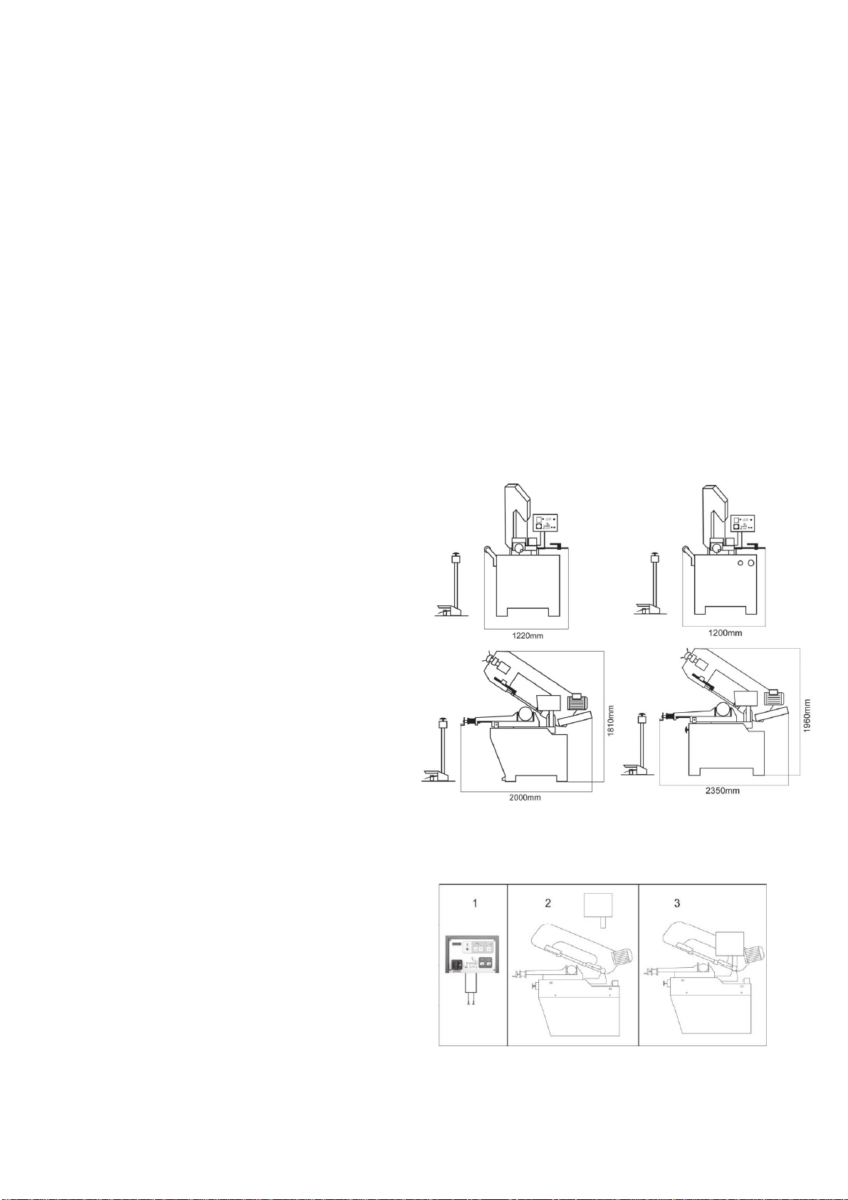
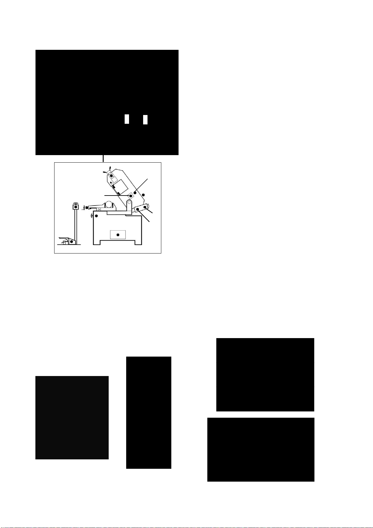
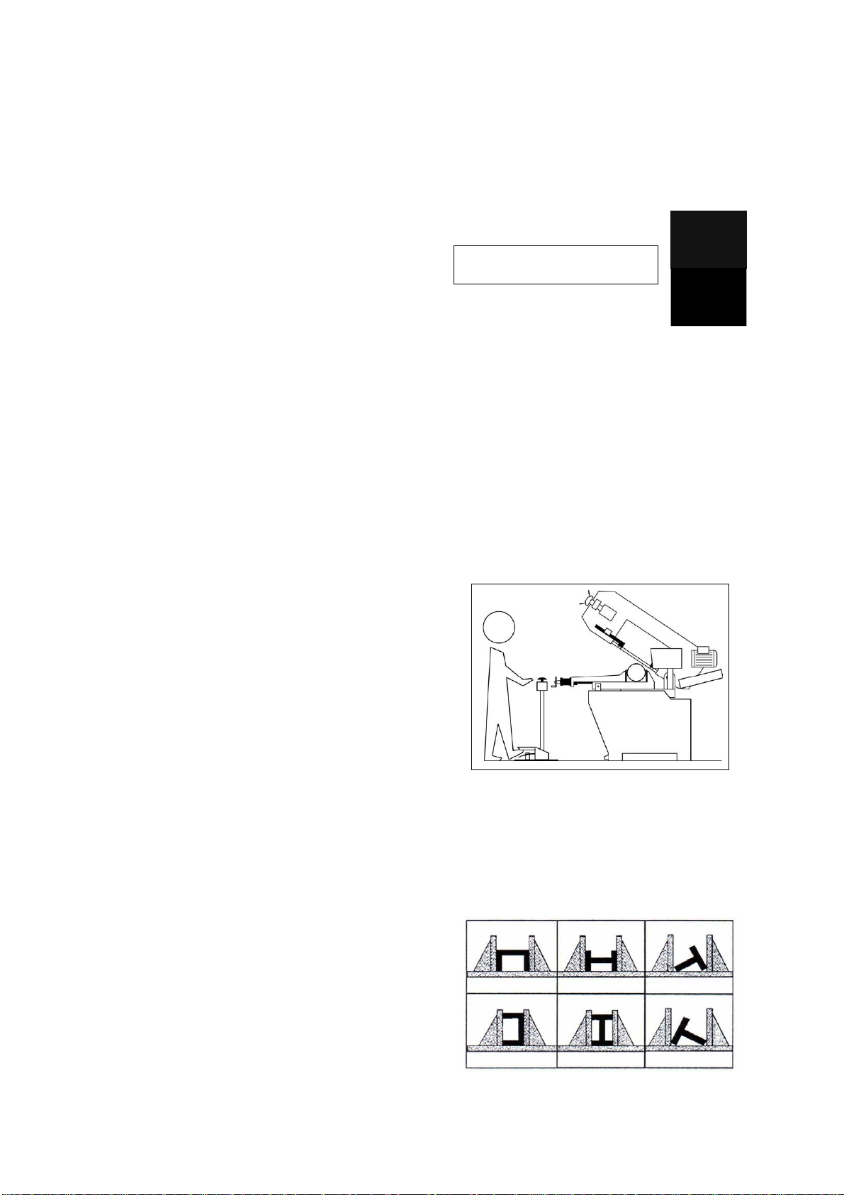
Only one operator is needed to use the machine,
that must stand as shown in the picture.
-The saw bow will return to the bow’s maximum
height upon completion of operation.
- In case of Emergency or problem during the
operation cycle, press the emergency push button
(H or I) down to shut off all functions.
-To release the emergency push button (H or I),
rotate the mushroom shaped button clock-wise.
The button will pop up and then the cutting cycle
can be restarted.
-The hydraulic start switch (G) will automatically
shut-off after 5 minutes of non-operation.
*Note: If the hydraulic start switch fails to activate,
then switch (C), (D), and (F) cannot operate.
Indicator light (7) will blink if any are pressed,
indicating that hydraulic start switch (G) has failed
to activate.
- Before starting each cutting operation, ensure that
the part is firmly clamped in the vise and that the
end is suitably supported.
-If the hand operation is selected and the footpad is
used, then the hand operation indicator light (4)
will blink. And vice versa, If the footpad operation
is selected and the hand switches are used, then
the foot operation indicator light (5) will blink.
They indicate improper selection.
- These figures below show examples of suitable
clamping of different section bars, bearing in mind
the cutting capacities of the machine in order to
achieve a good efficiency and blade durability.
-The appropriate indicator light will blink to indicate
which part of the machine has gone out of order.
1. Indicator light 14 indicates the emergency
button is pressed. Indicator light 16 indicates
the emergency button on foot pad is pressed.
2. Indicator light 13 indicates the band saw blade
has broken.
3. Indicator light 10 indicates the blade cover is
open. - Do not use blades of a different size from those
stated in the machine specifications.
4. Indicator light 12 indicates the motor has
overloaded.
-6
-

- If the blade gets stuck in the cut, press the cycle
start switch or emergency button to switch off the
machine. Open the vise slowly, remove the part
and check that the blade or its teeth are not
broken. If they are broken, change the blade.
5.2 Adjusting the blade guide
- Checksaw frame return spring to ensure proper
balancing.
- Before carrying out any repairs on the machine,
consult the dealer.
5ADJUSTING YOUR MACHINE
5.1 Blade tension assembly
The ideal tension of the blade is achieved rotating
the hand wheel until the needle reaches the proper
blade tension on the tension gauge (A).
The machine will not operate if the micro switch
does not actuate by contacting the tension device
(C).
If the tension is set properly, but the micro switch (B)
does not contact or trigger properly, make this
adjustment.
- Loosen the setscrews (D).
- Push the micro switch (B) towards the tension
device (C). Make sure that the plunger is
pressed properly.
- Tighten down the setscrews (D) to secure the
micro switch (B) in place.
- Disconnect the machine from the power source.
- Use a Hex. Wrench to loosen Hex. Socket screw
(A) on the square lock plate.
- Hold the handle (B) and slide blade guide block as
close as possible to the material without
interfering with the cut
- Tighten the hex. socket screw (A).
- Reconnect the machine to power source.
A
B
-7
-
A
BD
C
- Disconnect the machine from the power source.
- Loosen hex screw (L) on the guide bar clamp.
- Hold the handle (M) and slide blade guide bar so
that the blade guide is as close as possible to the
material without interfering with the cut.
-Tighten hex screw (L).
-Reconnect the machine to power source.
M
L
SX-827DGSVI
SX-823DGSVI
Blade guide blocks
The blade is guided by means of adjustable pads
set in place during inspection as per the thickness
of the blade with minimum play as shown.
When replacing the blade use a 0.9mm thick blade
for which the blade guides have been pre-set. For
of blades of another thickness, the adjustment
should be carried out as follows:
- Loosen nut (C), screw (B) and loosen dowel (D)
widening the passage between the pads.
- Loosen the nuts (H) and the dowels (I) and rotate
the pins (E - G) to widen the passage between the
bearings (F).
- To mount the new blade: place the pad (A) on the
blade, loosening the dowel, allow a play of 0.04
mm for the sliding of the toothed blade, lock the
relative nut and screw (B), Rotate the pins (E - G)
until the bearings rest against the blade as
indicated in the figure and then secure the dowels
(I) and nut (H).
- Make sure that between the blade and the upper
teeth of the pad (L) this is at least 0.2 - 0.3 mm of
play; if necessary, loosen the screwsthat fasten
the blocks and adjust accordingly.

-8
-
BEFORE PERFORMING THE FOLLOWING
OPERATIONS, THE ELECTRIC POWER SUPPLY
AND THE POWER CABLE MUST BE
COMPLETELY DISCONNECTED.
5.3 Changing the blade
To change the blade:
- Lift the saw arm.
- Loosen the blade with the blade tension hand
wheel, remove the blade-guards, open the blade
box cover and remove the old blade from the
blade wheels and the blade guide blocks.
- Place the new blade in between the blade guide
pads and on the race of the blade wheels. Check
the cutting direction of the teeth.
- Tension the blade. Check that it is seated
properly on the flywheels.
- Replace and fasten the blade guards and the
flywheel guard. Check the safety interlock switch
(N) is activated otherwise the machine will not
start.
WARNING: Always use blades with the same
thickness as specified by this manual to match the
blade guide’s factory setting; otherwise, see
chapter
N

5.6 Adjusting the blade to the flywheels5.4 Saw frame return stroke-limiting device
It consists in a mechanical adjustment system,
mounted parallel to the saw frame rise cylinder, to
reduce the passive phases of the operating cycle.
In other words it eliminates the idle stroke that takes
place when the size of the part to be cut is much
smaller than the maximum cutting capacity.
Practically, you adjust the starting position of the
blade in proximity of the part, independently of its
dimensions.
Operate as follows:
- Slightly open the flow regulation valve (A1).
- Bring the blade as near as 10mm from the work
piece with the bow up/bow down switches (C and
D).
- Loosen handle (7) to release the adjustable stop
(8) against the limit switch (9).
- Lock the handle (7)
ATTENTION:
- It is not necessary to adjust the mechanical stop
(8) every time; bring the blade near the workpiece
by means of bow switch (D) and then start the
automatic cutting cycle (F), which will begin
operation from this position of the blade.
- The bow will return to the upper end stroke.
5.5 Changing the blade
To change the blade:
- Lift the saw arm.
- Loosen the blade with the hand wheel, remove the
mobile blade-guard cover, open the flywheel
guards and remove the old blade from the
flywheels and the blade guide blocks.
- Assemble the new blade by placing it first between
the pads and then on the race of the flywheels,
paying particular attention to the cutting direction
of the teeth.
- Tension the blade and make sure it perfectly fits
inside the seat of the flywheels.
- Assemble the mobile blade-guide end, the
flywheel guard, and fasten it with the relative
knobs. Check that the safety micro switch is
activated otherwise when electric connection will
be restored the machine will not start.
1. Loosen the hex nut screws A, B, and C.
2. Use an Allen wrench on set screw D to adjust
the tilt of the flywheel.
-Turning the setscrew D clockwise will tilt flywheel
so that the blade will ride closer to the flange.
-Turning the setscrew D counter-clockwise with tilt
the flywheels that the blade will ride away from the
flange.
If the blade rides away too far then it will come off.
After the adjustment is finished, fasten the hex nut
screws in this order: A, B, and C.
Checking the adjustment of the blade
Use a strip of scrap paper and slide it between the
blade and the flywheel while it is running.
ATilt in this direction will cause the
b
l
ade to
ri
de to
w
a
r
ds t
h
e
fl
a
n
ge
ATilt in this direction will cause the
blade to ride awa
y
from the flan
g
e
Top view
Set screw D
flywheel
paper
Blade direction
-9
-
9
8
7
TOP
B
AC
Set screw D

-if the paper is cut then the blade is riding too close
to the flange. Re-adjust. 6.4 Six-monthly maintenance
- Continuity test of the equipment potential
protection circuit.-if you notice that the blade is riding away from the
flange. Then re-adjust. 6.5 Maintenance of other machine parts
The worm drive gearbox mounted on the machine
is maintenance-free guaranteed by itsmanufacture.
WARNING: Always assemble blades having
dimensions specified in this manual and for which
the blade guide heads have been set; otherwise,
seechapter on "Description of the operating cycle"
in the section Starting-up. 6.6 Oils for lubricating coolant
Considering the vast range of products on the
market, the user can choose the one most suited to
their own requirements, using as reference the type
SHELL LUTEM OIL ECO. THE MINIMUM
PERCENTAGE OF OIL DILUTED IN WATER IS 8 -
10 %.
5.7 Repla
cing saw frame return spring
- When performing this operation it is necessary to
support saw arm using the lifting device.
- Replace the spring by loosening the upper
coupling rod and releasing it from the lower
tie-rod. 6.7 Oil disposal
The disposal of these products is controlled by strict
regulations. Please see the Chapter on "Machine
dimensions Transport - Installation" in the
section on Dismantling.
6 ROUTINE AND SPECIAL
MAINTENANCE
THE MAINTENANCE JOBS ARE LISTED BELOW,
DIVIDED INTO DAILY, WEEKLY,MONTHLY AND
SIX-MONTHLYINTERVALS. IF THE
FOLLOWING OPERATIONS ARE NEGLECTED,
THERESULT WILL BE PREMATURE WEAR OF
THE MACHINE AND POORPERFORMANCE.
6.1 Daily maintenance
- General cleaning of the machine to remove
accumulated shavings.
- Clean the lubricating coolant drain hole to avoid
excess fluid.
- Top off the level of lubricating coolant.
- Check blade for wear.
- Rise of saw frame to top position and partial
slackening of the blade to avoid useless yield
stress.
- Check functionality of the shields and emergency
stops.
6.2 Weekly maintenance
- Thorough cleaning of the machine to remove
shavings, especially from the lubricant fluid tank.
- Removal of pump from its housing, cleaning of the
suction filter and suction zone.
- Clean the filter of the pump suction head and the
suction area.
- Use compressed air to clean the blade guides
(guide bearings and drain hole of the lubricating
cooling).
- Cleaning flywheel housings and blade sliding
surfaces on flywheels.
6.3 Monthly maintenance
- Check the tightening of the motor flywheel screws.
- Check that the blade guide bearings on the heads
are perfect running condition.
- Check the tightening of the screws of the gear
motor, pump, and accident protection guarding.
-10-
6.8 Coolant system
P
N
Cleaning the tank
-Use hex wrench to open the drain plug to allow
the coolant to drain out.
-Remove the hose and filter (N).
-Remove the pump (P) by loosening the 2 set
screws.
-Use a vacuum cleaner to vacuum chips and
debris from the tank.
-Replace the drain plug. Thoroughly clean the
pump (P) and replace.
-Fill tank with coolant to a level about 25mm
below the filter.
-Replace the hose and filter.

-11-
6.9 The gearbox
6.10 Special maintenance
Special maintenance must be conducted by skilled
personnel. We advise contacting your nearest
dealer and/or importer. Also the reset of protective
and safety equipment and devices (of the reducer),
the motor, the motor pump, and other electrical
components requires special maintenance.
7TECHNICAL CHARACTERISTICS
7.1 Table of cutting capacity and technical
details
SX-823DGSVI
Q
R, S
The gear box requires periodic changing of oil.
The oil must be changed by the first 6 months of a
new machine and every year thereafter.
To change the gear box oil
-Disconnect the machine from the power
source.
-Raise the saw arm to vertical position
-Release the drain hold (R) to draw off gear oil
by loosening the hex socket screw (S).
-Replace the screw (S) after oil completely flows
off.
-Place the saw arm back to horizontal position.
-Fill Gear box with approximately .3 liter of gear
oil through the hole of the vent screw (Q)
For reference, use SHELL type gear oil or Mobile
gear oil #90.

8MATERIAL CLASSIFICATION
AND CHOICE OF TOOL 8.1 Definition of materials
The table above lists the characteristics of the
materials to be cut. So as to choose the right tool to
use.
Since the aim is to obtain excellent cutting quality,
the various parameters such as hardness of the
material, shape and thickness, transverse cutting
section of the part to be cut, selection of the type of
cutting blade, cutting speed and control of saw
frame lowering. These specifications must therefore
be harmoniously combined in a single operating
condition according to practical considerations and
common sense, so as to achieve an optimum
condition that does not require countless operations
to prepare the machine when there are many
variations in the job to be performed. The various
problems that crop up from time to time will be
solved more easily if the operator has a good
knowledge of these specifications.
8.2 Selecting blade
First of all the pitch of the teeth must be chosen, in
other words, the number of teeth per inch (25,4 mm)
suitable for the material to be cut, according to
these criteria:
- Parts with a thin and/or variable section such as
profiles, pipes and plate, need close tooth, so that
the number of teeth used simultaneously in cutting
is from 3 to 6;
- Parts with large transverse sections and solid
sections need widely spaced tooth to allow for the
greater volume of the shavings and better tooth
penetration;
-12-
SX-827DGSVI

- Parts made of soft material or plastic (light alloys,
mild bronze, Teflon, wood, etc.) also require
widely spaced tooth;
8.6 Blade structure
Bi-metal blades are the most commonly used. They
consist of a silicon-steel blade backing by a laser
welded high speed steel (HHS) cutting edge. The
type of stocks are classified in M2, M42, M51 and
differ from each other because of their major
hardness due to the increasing percentage of
Cobalt (Cc) and molybdenum (Mo) contained in the
metal alloy
- Pieces cut in bundles require combo tooth design.
8.3 Teeth pitch
As already stated, this depends on the following
factors:
- Hardness of the material
- Dimensions of the section
- Wall thickness. 8.7 Blade type
They differ essentially in their constructive
characteristics, such as:
-Shape and cutting angle of tooth
-Pitch
-Set
Shape and angle of tooth
REGULAR TOOTH: Oº rake and constant pitch.
Mostcommon form for transversal or inclined
cutting of solid small and average cross-sections or
pipes, in laminated mild steel and gray iron or
general metal.
POSITIVERAKETOOTH: 9º - 10º positive rake
and constant pitch.
8.4 Cutting and advance speed
The cutting speed (m/min) and the advance speed
(cm2/min =area traveled by the diskteeth when
removing shavings) are limited by the development
of heat close to the tips of the teeth. Particular use for crosswise or inclined cuts in solid
sections or large pipes, but above all harder
materials (highly alloyed and stainless steels,
special bronze and forge pig iron).
- The cuttingspeed is subordinate to the resistance
of the material (R = N/mm2), to itshardness (HRC)
and to the dimensions of the widest section.COMBO TOOTH: pitchvaries between teeth and
consequently varying teeth size and varying gullet
depths. Pitch varies between teeth, which ensures
a smoother, quieter cut and longer blade life owing
to the lackof vibration.
- Too high an advance speed (= lowering of the saw
frame) tends to cause the disk to deviate from the
ideal cutting path, producing non rectilinear cuts
on bath the vertical and the horizontal plane.
The best combination of these two parameters can
be seen directly examining the chips.
Long spiral-shaped chips indicate ideal cutting.
Very fine or pulverized chips indicate lack of feed
and/or cutting pressure.Another advantage offered in the use of this type of
blade in the fact that with an only blade it is possible
to cut a wide range of different materials in size and
type.
Thick and/or blue chipsindicate overload of the
blade.
8.5 Blade running-in
When cutting for the first time, it is good
practice to run in the tool making a series of
cuts at a low advance speed (= 30-35 cm2/min on
material of average dimensions with respect to the
cutting capacity and solid section of normal steel
with R = 410-510 Nimm2). Generously spraying
the cutting area with lubricating coolant.
COMBO TOOTH: 9º - 10º positive rake.
-13
-

This set is associated with very fine teeth and it is
mainly used for the cutting of pipes and thin section
bars (from 1 to 3 mm).
ALTERNATE SET (IN GROUPS): Groups of cutting
teeth right and left, alternated by a straight tooth.
This type of blade is the most suitable for the
cutting of section bars and large and thick pipes as
well as for the cutting of solid bars at maximum
machine capacity. Available pitches: 3-4/4-6.
This set is associated with very fine teeth and it is
used for extremely thin materials (less than 1mm).
SETS
Saw teeth bent out of the plane of the saw body,
resulting in a wide cut in the workpiece. ALTERNATE SET (INDIVIDUAL TEETH): Cutting
teeth right and left.
REGULAR OR RAKER SET: Cutting teeth right
and left, alternated by a straight tooth.
This set is used for the cutting of nonferrous soft
materials, plastics and wood.
Of general use for materials with dimensions
superior to 5 mm. Used for the cutting of steel,
castings and hard nonferrous materials.
WAVY SET: Set in smooth waves.
9 NOISE TESTS
The test was held under environmental noise levels of 65db. Noise measurements with the machine
operating unload was 71db. Noise level during the cutting of mild carbon steel was 73db.
NOTE: with the machine operating, the noise level will vary according to the different materials being
processed. The user must therefore assess the intensity and if necessary provide the operators with the
necessary personal protection, as required by Law 277/1991.
-14
-

1 2 3 4 5 6 7 8
A
B
C
D
8
7
6
543
2
1
D
C
B
A
Y1 Y3Y2
FU3
FU1
FU2
FU4
FU5
FU7
VR1
Date:08/06/2008
Revision
Number
A3
Size
Title
O.L of M1
FS1
T2
S2
R2
1K
COM
FWD
Meter
K1
A2 A1
K3
1.5HP, 380V-415V 12A:PH5.2 ~3
2HP:
5A
23V
/
25V
/
Inverter
Inverter
X1:12X6:3
X6:3
65
SB4
E-STOP SW
of Machine
W U
S R
6 4 2
5 3 1
X6:13
X6:13 X7:15 SW of foot
72
SF1
Limit of UPPER
SQ3
13
BOARD)
WT-M1V3
WT-M3-TL VER2
X6:5 X6:5
X6:6 X6:6
68
SQ5
Limit SW
of COVER Out
X1:15
X6:1
X6:2 X6:2
X6:1
6761
SQ1
Limit SW
of SAW Broken
X1:11
X1:14
X6:9
X6:8
X6:10
X6:14
X6:12
X6:8
X6:9
X6:12
X6:14
X6:10
X7:14
X7:13
X7:17
X7:16
X1:20
X1:19
X1:18
X1:17
X1:16
737169 70
Limit of DOWNNER
O.L of M2
ALARM of M1
SQ4
FS2
(TRANSFERENCE
21
X7:22
11
10 12
353117
9
1514
20
19
7
6
5
4
93
2 1
55
54
58
57
W1
59
U1
T1
R1
0V
FS2
K2
E
M1
MOTOR
of SAW 1/2HP
of Hydraulic
MOTOR
M2
E
X8:3 X8:5
X8:4
T1
X8:17
X8:18
X8:19
X8:16
NO:DSAV3P-C-H-V2
2 1
V3
SQ5
SQ1
E
V 2 1V 0V 0 24V
24V
M.C of M1
M.C of M2
PCB1
PCB2
X1:6
X1:7
FS1
SB4
FS2
K2K1
Valve
Valve
of DOWN
of UP
Valve
of clamp
of vice
Valve
SA1380V-415V 10A3~
M3
MOTOR
of COOLANT
1/6HP
K3
L1
L2
L3
PE
R
S
T
R1
S1
T1
A1
A2
A1
A2
X1:9
0V (220V,380V
400V,415V)
(MAIN CONTROL BOARD)
1.5A5.5A
X8:20
X8:21
X8:23
X8:25
X7:1
X7:2
X7:21
X7:20
X7:19
X7:18
X7:4
X7:3
X7:7
X7:10
X7:8
1.5A
380-415V :1A
X7:22
95
96
95
96
1
2
11
12
11
12
unclamp
PCB2
Sheet of
Drawn By: P3
Motors & All Output Parts
X3:6
X3:7
X2:4
X2:3
X2:2
X2:1
X2:1
X2:2
X2:3
X2:4
X3:7
X3:6
X3:8
X3:9
X3:10
X3:11
X3:3
X3:4
X3:4
X3:3
X3:11
X3:10
X3:9
X3:8
2
1
X8:22
SB1
8
X8:24
22
GND
12V
Vin
DC24V
of FOOT SW
E-STOP SW
66
X6:4 X6:4 X1:13
SB1
Ta1
Tc1
Y4
X8:3
V1
V
T
K1
FS1
8990
FU9
1.6A FU10
1A
4342
10 WIRING DIAGRAMS SX-823DGSVI
-15
-

12 3 4
A
B
C
D
4
3
21
D
C
B
A
A4
of
Drawn By: P3
Date:08/06/2008
Number
Size
Title
Revision
2 2
V3
X7:14 POLE CHAGER
X6:12
X7:13
7473
SA2
72717069
68
61
67
61
66
61
65
X1:11
X1:11
)+( )+(
DC 24V
X6:14
X6:13
X6:10
X6:9
X6:8
PCB2
PCB1
Limit of UPPER
SW of foot
Limit of DOWNNER
O.L of M2
O.L of M1
X7:17
X7:16
SQ3
X7:15
SF1
X7:13
X1:20
SQ4
X1:11
X1:12
X1:13
X1:14
X1:15
X6:6
X6:5
X6:4
X6:3
X6:1
X6:2
X1:16
SB4SB1SQ1SQ5
FS1
FS2
X1:17
X1:18
X1:19
E-STOP SW
of Machine
of FOOT SW
E-STOP SW
Limit SW
of SAW Broken
Limit SW
of COVER Out
1 61 61 61 61 6
Sheet :
X6:2
X6:1
X6:3
X6:4
X6:5
X6:6
X6:8
X6:9
X6:10
X6:13
X6:14
X6:12
(TRANS BOARD)
(MAIN BOARD)
X8:10
X8:8
X8:9
X8:13
X8:12
X8:28
X8:11
X8:11
X8:10
X8:10
X7:13
X7:13
61
61
-16
-
SX-823DGSVI

10 WIRING DIAGRAMS SX-827DGSVI
- 17
-
Y1 Y3
Y2
FU3
FU1
FU2
FU4
FU5
FU7
VR1
O.L of M3
FS1
T2
S2
R2
1K
COM
FWD
Meter
K1
A2 A1
K3
1.5HP,
380V-415V 12A:PH5.2 ~3
2HP:
5A
23V
/
25V
/
Inverter
Inverter
X1:12X6:3
X6:3
65
SB4
E-STOP SW
of Machine
W U
S R
6 4 2
5 3 1
X6:13
X6:13 X7:15
SW of foot
72
SF1
Limit of UPPER
SQ3
13
BOARD)
WT-M1V3
WT-M3-TL VER2
X6:5 X6:5
X6:6 X6:6
68
SQ5
Limit SW
of COVER Out
X1:15
X6:1
X6:2 X6:2
X6:1
6761
SQ1
Limit SW
of SAW Broken
X1:11
X1:14
X6:9
X6:8
X6:10
X6:14
X6:12
X6:8
X6:9
X6:12
X6:14
X6:10
X7:14
X7:13
X7:17
X7:16
X1:20
X1:19
X1:18
X1:17
X1:16
737169 70
Limit of DOWNNER
O.L of M2
ALARM of M1
SQ4
FS2
(TRANSFERENCE
21
X7:22
11
10 12
353117
9
1514
20
19
7
6
5
4
9
3
2 1
55
54
58
57
W1
59
U1
T1
R1
0V
FS2
K2
E
M1
MOTOR
of SAW
1/2HP
of Hydraulic
MOTOR
M2
E
X8:3
X8:5
X8:4
T1
X8:17
X8:18
X8:19
X8:16
SQ5
SQ1
E
V 2 1V 0V 0
24V
24V
M.C of M1
M.C of M2
PCB1
PCB2
X1:6
X1:7
FS1
SB4
FS2
K2K1
Valve
Valve
of DOWN
of UP
Valve
of clamp
of vice
Valve
SA1380V-415V 10A3~
M3
MOTOR
of COOLANT
1/6HP
K3
L1
L2
L3
PE
R
S
T
R1
S1
T1
A1
A2
A1
A2
X1:9
0V (220V,380V
400V,415V)
(MAIN CONTROL BOARD)
1.5A5.5A
X8:20
X8:21
X8:23
X8:25
X7:1
X7:2
X7:21
X7:20
X7:19
X7:18
X7:4
X7:3
X7:7
X7:10
X7:8
1.5A
380-415V :1A
X7:22
95
96
95
96
1
2
11
12
11
12
unclamp
PCB2
X3:6
X3:7
X2:4
X2:3
X2:2
X2:1
X2:1
X2:2
X2:3
X2:4
X3:7
X3:6
X3:8
X3:9
X3:10
X3:11
X3:3
X3:4
X3:4
X3:3
X3:11
X3:10
X3:9
X3:8
2
1
X8:22
SB1
8
X8:24
22
GND
12V
Vin
DC24V
of FOOT SW
E-STOP SW
66
X6:4 X6:4
X1:13
SB1
Ta1
Tc1
Y4
X8:3
V1
V
T
K1
FS1
8990
FU9
1.6A FU10
1A
4342

- 18
-
X7:14 POLE CHAGER
X6:12
X7:13
7473
SA2
72717069
68
61
67
61
66
61
65
X1:11
X1:11
)+( )+(
DC 24V
X6:14
X6:13
X6:10
X6:9
X6:8
PCB2
PCB1
Limit of UPPER
SW of foot
Limit of DOWNNER
O.L of M2
O.L of M1
X7:17
X7:16
SQ3
X7:15
SF1
X7:13
X1:20
SQ4
X1:11
X1:12
X1:13
X1:14
X1:15
X6:6
X6:5
X6:4
X6:3
X6:1
X6:2
X1:16
SB4SB1SQ1SQ5
FS1
FS2
X1:17
X1:18
X1:19
E-STOP SW
of Machine
of FOOT SW
E-STOP SW
Limit SW
of SAW Broken
Limit SW
of COVER Out
1 61 61 61 61 6
X6:2
X6:1
X6:3
X6:4
X6:5
X6:6
X6:8
X6:9
X6:10
X6:13
X6:14
X6:12
(TRANS BOARD)
(MAIN BOARD)
X8:10
X8:8
X8:9
X8:13
X8:12
X8:28
X8:11
X8:11
X8:10
X8:10
X7:13
X7:13
61
61
SX-827DGSVI
This manual suits for next models
1
Table of contents
Languages:
Other Promac Saw manuals

Promac
Promac 348C User manual

Promac
Promac SY-350V User manual

Promac
Promac MBS-910CS User manual

Promac
Promac 349V User manual

Promac
Promac SX-821DA User manual

Promac
Promac SY-350-ALU Service manual

Promac
Promac SY-315 User manual

Promac
Promac SX-824DG User manual

Promac
Promac MBS-56CS-M User manual

Promac
Promac 347V Service manual